Sign In
Upload
Manuals
Brands
Canon Manuals
All in One Printer
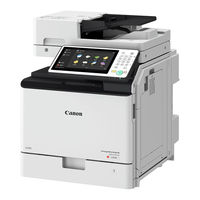
imageRUNNER ADVANCE C355 Series
Canon imageRUNNER ADVANCE C355 Series Manuals
Manuals and User Guides for Canon imageRUNNER ADVANCE C355 Series. We have
1
Canon imageRUNNER ADVANCE C355 Series manual available for free PDF download: Service Manual
Canon imageRUNNER ADVANCE C355 Series Service Manual (987 pages)
Brand:
Canon
| Category:
All in One Printer
| Size: 65.37 MB
Table of Contents
Service Manual
1
Table of Contents
4
Safety Precautions
12
Laser Safety
13
Handling of Laser System
13
Turn Power Switch on
14
Power Supply
14
Toner Safety
14
About Toner
14
Handling Adhered Toner
14
Notes When Handling a Lithium Battery
15
Notes before It Works Serving
15
Points to Note at Cleaning
15
Notes on Assembly/Disassembly
15
Points to Note When Tightening a Screw
16
1 Product Overview
17
Product Lineup
18
Host Machine
18
Machine Configuration
18
Model Type
18
Pickup/Delivery / Image Reading System Options
19
Option
19
Function Expansion System Options
20
Features
22
Improved Operability of Replacing Major Parts
22
Specifications
25
Weight and Size
26
Productivity
27
Paper Type
27
Parts Name
29
Cross Section View
29
Control Panel
30
2 Technology
31
Functional Configuration
32
Original Exposure System
33
Features
33
Specifications
33
Basic Configuration
34
Adf Unit
35
Dust Detection Control
37
Image Processing
38
Shading Correction
39
Outline of Electric Circuits
41
ADF Scan Operation Sequence (Common to 2-Sided/1-Sided)
42
Scanner Unit
44
Pickup Feed System
45
Original Detection
46
Controller System
50
Overview
50
Startup Sequence
52
Shutdown Sequence
53
Motion Sensor
53
Laser Exposure System
54
Overview
54
Specifications
55
Laser ON/OFF Control
56
Horizontal Scanning Synchronization Control
57
Vertical Scanning Synchronization Control
58
Scanner Motor Control
59
APC (Auto Power Control)
60
BD Detection Correction Control
61
Dustproof Shutter
61
Image Formation System
62
Overview
62
Major Parts
63
Print Process
63
Primary Charging
64
Drum Unit (Developing/Drum)
65
Developing Bias Control
66
Transfer
69
Atvc Control
71
Drum Cleaning
75
Image Stabilization Control
76
Toner Supply Assembly
78
Detection Timing
79
Toner Supply Control
82
Toner Level Detection
84
Waste Toner Feeding Area
85
Other Controls
87
Operation Overview
88
Fixing System
90
Overview
90
Specifications
90
Component Parts
90
Fixing Temperature Control
92
Standby Temperature Control
93
Print Temperature Control
94
Down Sequence Control
95
Fixing Film Unit Engagement/Disengagement Control
97
Pre-Fixing Arch Level Control
98
Arch Sensor Control
99
Protection Function
100
Pickup Feed System
102
Overview
102
Cassette Pickup Assembly
105
Paper Size Detection Control
106
Multi-Purpose Tray Pickup Assembly
109
Fixing/Registration Assembly
110
Delivery Assembly
112
Reverse/Duplex Assembly
113
Jam Detection
116
External Auxiliary System
119
Software Counter
119
Fan
121
Power Supply
123
Power-Saving Function
123
Quick Startup
125
Operating Conditions of the Heater Control
126
3 Periodical Service
127
Periodically Replacement Parts
128
Consumable Parts
129
4 Parts Replacement and Cleaning
130
Preface
131
Outline
131
Points to Note When Tightening a Screw
131
List of Parts
132
External / Internal Cover
132
List of Main Unit
136
Electrical Components
140
External Cover/Interior System
150
Removing the Front Cover
150
Removing the Rear Cover 1
151
Removing the Left Upper Cover
155
Removing the Left Lower Cover
155
Removing the Right Front Cover
156
Removing the Right Rear Cover/Right Rear Lower Cover
157
Removing the Left Upper Cover
158
Removing the Right Cover Unit
160
Removing the Multi-Purpose Tray
166
Removing the Delivery Tray
167
Removing the Rear Upper Cover
168
Removing the Upper Cover
170
Removing the Control Panel Unit
172
Original Exposure/Feed System
178
Removing the ADF Unit
178
Removing the ADF Pickup Unit
184
Removing the ADF Separation Unit
185
Removing the Scanner Unit (Back)
186
Removing the Copyboard Glass Unit
193
Removing the Scanner Unit (Front)
194
Removing the Reader Motor
198
Controller System
200
Removing the Main Controller Unit
200
Removing the DC Controller PCB
205
Removing the Secondary Transfer High-Voltage Pcb/Developing High-Voltage PCB Unit
207
Removing the Primary Transfer High-Voltage PCB Unit
208
Removing the All-Night Power Supply PCB Unit
211
Removing the Low-Voltage Power Supply Unit
212
Removing the Touch Panel/Control Panel CPU PCB Unit/Lcd Unit
217
Removing the HDD
223
Removing the Fax Speaker Unit
225
Removing the Fax Unit
225
Laser Exposure System
227
Removing the Laser Scanner Unit
227
Image Formation System
232
Removing the Waste Toner Container
232
Removing the Toner Container (Y/M/C/Bk)
232
Removing the Drum Unit (Y/M/C/Bk)
233
Removing the ITB Unit
236
Removing the Registration Patch Sensor Unit
241
Removing the Secondary Transfer Outer Roller Unit
243
Removing the Secondary Transfer Outer Roller Guide Unit
244
Removing the Registration Drive Unit
249
Removing the Main Drive Unit
251
Removing the Hopper Unit (Y/M/C/Bk)
252
Removing the ITB Pressure Release Switch
255
Removing the Bottle Drive Unit (Y/M/C/Bk)
256
Removing the Toner Bottle Mount (Y/M/C/Bk)
258
Fixing System
265
Removing the Fixing Assembly
265
Removing the Fixing Film Unit / Pressure Roller Unit
266
Removing the Fixing Drive Unit
270
Pickup/Feed System
272
Removing the Right Inner Cover Unit
272
Removing the Cassette Pickup Roller/Cassette Separation Roller/Cassette Feed Roller
273
Removing the Multi-Purpose Tray Pickup Roller /Multi-Purpose Tray Separation Roller /Multi-Purpose Tray Feed Roller
278
Removing the Registration/Pickup Unit
290
Procedure after Replacement When Images with Uneven Density (White Spots) Are Generated after Replacing the Registration Unit
294
Removing the Delivery/Reverse Unit
300
Removing the Cassette 1 Lifter Drive Unit
301
Removing the Cassette 1 Pickup Drive Unit
304
Cleaning Procedure
307
Cleaning the Copyboard Glass/Reading Glass
307
Cleaning the Dustproof Glass
307
Cleaning When Installing/Removing the ITB Unit
308
Cleaning the Registration Patch Sensor Unit
309
Cleaning the Registration Front Guide
311
Cleaning the Registration Roller/Pre-Registration Roller
312
Cleaning the Secondary Transfer Guide
314
Cleaning the Fixing Inlet Guide
315
5 Adjustment
317
Actions at Parts Replacement
318
Main Controller PCB
318
DC Controller PCB
318
Works Required at HDD Replacement
319
After Replacing the Copyboard Glass
321
After Replacing the Scanner Unit (Front)
321
After Replacing the Scanner Unit (Back)
322
Original Exposure System
324
Right Angle Adjustment
324
Pickup Feed System
325
Image Position Adjustment
325
Feed Direction
329
6 Troubleshooting
330
List of Initial Check Items
331
Test Print
332
Overview
332
Steps to Select a Test Print Type
332
How to Use the Test Print
333
List of Troubleshooting Items
336
Image Failure
336
Category: Malfunction
342
Startup System Failure Diagnosis
346
Overview
346
Startup System Failure Diagnosis Flow
347
Controller Self Diagnosis
356
Boot Method
357
Diagnosis Result
358
Controller System Error Diagnosis Table
358
Debug Log
361
Function Overview
361
Flow of Determining the Procedure for Obtaining Logs
363
Saving and Collecting Sublogs
364
7 Error/Jam/Alarm
376
Overview
377
Location Code
377
Pickup Position Code
377
Pickup Size
377
Points to Note When Clearing MN-CON
379
Points to Note When Clearing HDD
379
Eerror Code
380
Eerror Code Details
380
Jam Code
468
Jam Type
468
Jam Screen Display Specification
468
Host Machine / Cassette
469
ADF / Reader
472
Staple Finisher
473
Alarm Code
475
Alarm Code Details
475
8 Service Mode
491
Overview
492
Points to Note When Executing Service Mode
492
Service Mode Menu
492
Description of Service Mode Items
492
Operation Check of Electrical Components
493
Enhanced I/O Information
496
Security Support
498
Switching the Screen Display (Level 1 <->2)
499
Service Mode Backup
499
Output of Service Print Data
500
SITUATION Mode
504
Function to Mask the Screen During Remote Access
504
COPIER (Service Mode for Copier)
508
DISPLAY (State Display Mode)
508
I/O (I/O Display Mode)
588
ADJUST (Adjustment Mode)
593
FUNCTION (Operation / Inspection Mode)
701
OPTION (Specification Setting Mode)
721
TEST (Print Test Mode)
838
COUNTER (Counter Mode)
844
FEEDER (ADF Service Mode)
865
ADJUST (Adjustment Mode)
865
FUNCTION (Operation / Inspection Mode)
866
OPTION (Specification Setting Mode)
868
SORTER (Service Mode for Delivery Options)
869
ADJUST (Adjustment Mode)
869
OPTION (Specification Setting Mode)
869
BOARD (Option Board Setting Mode)
870
OPTION (Specification Setting Mode)
870
9 Installation
871
How to Check the Installation Procedure
872
Symbols
872
Installation
873
Host Mashine Installation
873
Setting the Dehumidification Switch
873
Document Scan Lock Kit-B1
874
Points to Note at Installation
874
Installation Outline Drawing
874
Checking the Contents
874
Check Item When Turning off the Main Power
874
Removing the Covers
875
Installation Procedure
877
Installing the Covers
879
Checking after Installation
879
IC Card Reader BOX-D1
880
Points to Note at Installation
880
Installation Outline Drawing
880
Checking the Contents
880
Check Item When Turning off the Main Power
881
Preparation
881
Removing the Covers
884
Installation Procedure
889
IC Card Reader Attachment-A1
898
Points to Note at Installation
898
Copy Card Reader-F1/Copy Card Reader Attachment-B4
904
Check Item When Turning off the Main Power
905
Installing the Covers
911
Installation Procedure
912
Setting after Installation
916
Serial Interface Kit-K3, Copy Control Interface Kit-A1
917
Check Item When Turning off the Main Power
918
NFC Kit-C1
928
Setting after Installation
938
Connection Kit-A1 for Bluetooth LE
939
Setting after Installation
942
Appendices
943
Service Tool
944
General Circuit Diagram
947
Host Machine_2/13
948
Host Machine_3/13
949
Host Machine_4/13
950
Host Machine_5/13
951
Host Machine_6/13
952
Host Machine_7/13
953
Host Machine_8/13
954
Host Machine_9/13
955
Host Machine_10/13
956
Host Machine_11/13
957
Host Machine_12/13
958
Host Machine_13/13
959
Software Counter Specifications
960
Removal
965
Target Pcbs of Automatic Update
968
List of Service Modes that Can be Restored
969
Advertisement
Advertisement
Related Products
Canon imageRUNNER ADVANCE C355P
Canon imageRUNNER ADVANCE C355iFC
Canon imageRUNNER ADVANCE C355i
Canon imageRUNNER ADVANCE C3525i II
Canon imageRUNNER ADVANCE C3520 III
Canon imageRUNNER ADVANCE C351i
Canon imageRUNNER ADVANCE C3530i
Canon imageRUNNER ADVANCE C3525i
Canon imageRUNNER ADVANCE C356i III
Canon imageRUNNER ADVANCE C356i
Canon Categories
Printer
Digital Camera
All in One Printer
Camcorder
Scanner
More Canon Manuals
Login
Sign In
OR
Sign in with Facebook
Sign in with Google
Upload manual
Upload from disk
Upload from URL