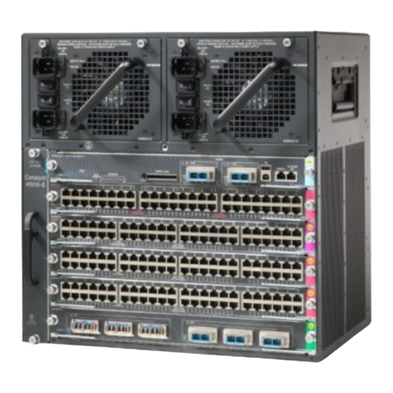
Cisco 4500 Installation Note
Fan tray assemblies
Hide thumbs
Also See for 4500:
- Software configuration manual (2086 pages) ,
- Administration manual (1814 pages) ,
- Configuration manual (1610 pages)
Table of Contents
Advertisement
Quick Links
Installation Note for Fan Tray Assemblies in
Catalyst 4500 Series Switches
Fan Assembly Overview
For complete environmental specifications, including airflow requirements, refer to Appendix A,
Note
"Specifications," in the Catalyst 4500 Series Installation Guide. The guide is available online at
http://www.cisco.com/en/US/docs/switches/lan/catalyst4500/hardware/installation/guide/78-14409-08/
4500inst.html
The system fan assembly provides cooling air for the internal chassis components. The fan assembly is
a tray of fans that you can insert and remove from the chassis while the system is on line. The
Catalyst 4503 fan assembly has two fans, the Catalyst 4506 fan assembly has four fans, and the
Catalyst 4507R fan assembly has six fans. The fans draw in fresh air from one side and exhaust air on
the other side. Catalyst 4503 airflow is shown in
Catalyst 4507R airflow is shown in
You must install module filler plates on unused switching module slots to ensure proper airflow.
Caution
Removing and replacing fan trays produced between September 2002 and November 2002 might require
Caution
rebooting the switch in a Catalyst 4506 switch with a Supervisor Engine III or Supervisor Engine IV and
in a Catalyst 4507R switch with Supervisor Engine IV. Starting in December 2002, Cisco added a white
strip on the bottom of the fan tray label to identify improved fan trays that do not have this limitation.
Corporate Headquarters:
Cisco Systems, Inc., 170 West Tasman Drive, San Jose, CA 95134-1706 USA
Copyright © 2002. Cisco Systems, Inc. All rights reserved.
Figure
1. Catalyst 4506 airflow is shown in
Figure
3.
Figure
2.
Advertisement
Table of Contents

Summary of Contents for Cisco 4500
-
Page 1: Catalyst 4500 Series Switches
Fan Assembly Overview For complete environmental specifications, including airflow requirements, refer to Appendix A, Note “Specifications,” in the Catalyst 4500 Series Installation Guide. The guide is available online at http://www.cisco.com/en/US/docs/switches/lan/catalyst4500/hardware/installation/guide/78-14409-08/ 4500inst.html The system fan assembly provides cooling air for the internal chassis components. The fan assembly is a tray of fans that you can insert and remove from the chassis while the system is on line. - Page 2 Fan Assembly Overview Figure 1 Catalyst 4503 Airflow 45 06 Fan assembly Figure 2 Catalyst 4506 Airflow 45 06 Fan assembly Installation Note for Fan Tray Assemblies in Catalyst 4500 Series Switches 78-15335-01...
-
Page 3: Removing And Replacing The Chassis Fan Assembly
Figure 3 Catalyst 4507R Airflow Fan assembly Removing and Replacing the Chassis Fan Assembly This section describes how to remove and install the chassis fan assembly for the Catalyst 4500 series switches. See fan assembly, and Required Tools You will need a Phillips screwdriver for the following two procedures. - Page 4 Removing and Replacing the Chassis Fan Assembly Figure 4 Catalyst 4503 System Fan Assembly Fan assembly Captive installation screws Figure 5 Catalyst 4506 System Fan Assembly Fan assembly Captive installation screws Installation Note for Fan Tray Assemblies in Catalyst 4500 Series Switches 78-15335-01...
-
Page 5: Removing The Fan Assembly
ETHE RNET SWIT CHIN G MODU 10/10 0BAS ETHE RNET E-TX MULT I-SPE ED GIGA BIT ETHE RNET SWIT CHIN G MODU Installation Note for Fan Tray Assemblies in Catalyst 4500 Series Switches Removing and Replacing the Chassis Fan Assembly... -
Page 6: Installing The Fan Assembly
Slide the fan assembly into the chassis until the two captive installation screws make contact with the chassis. Using a screwdriver, tighten the two captive installation screws by turning them clockwise. Step 4 Installation Note for Fan Tray Assemblies in Catalyst 4500 Series Switches 78-15335-01... -
Page 7: Verifying The Installation
Access Registrar, Aironet, AsyncOS, Bringing the Meeting To You, Catalyst, CCDA, CCDP, CCIE, CCIP, CCNA, CCNP, CCSP, CCVP, Cisco, the Cisco Certified Internetwork Expert logo, Cisco IOS, Cisco Press, Cisco Systems, Cisco Systems Capital, the Cisco Systems logo,... - Page 8 Obtaining Documentation and Submitting a Service Request Installation Note for Fan Tray Assemblies in Catalyst 4500 Series Switches 78-15335-01...


