Sign In
Upload
Manuals
Brands
ABB Manuals
Industrial Equipment
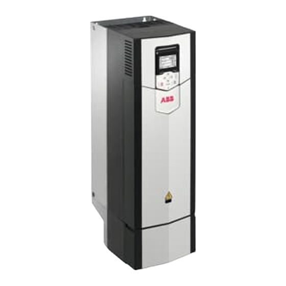
ACS880 N5700 Series
ABB ACS880 N5700 Series Manuals
Manuals and User Guides for ABB ACS880 N5700 Series. We have
1
ABB ACS880 N5700 Series manual available for free PDF download: Firmware Manual
ABB ACS880 N5700 Series Firmware Manual (662 pages)
Position control program
Brand:
ABB
| Category:
Industrial Equipment
| Size: 9.87 MB
Table of Contents
Table of Contents
5
Introduction to the Manual
15
What this Chapter Contains
15
Applicability
15
Licensing
16
Safety Instructions
16
Target Audience
17
Related Manuals
17
Terms and Abbreviations
18
Cybersecurity Disclaimer
20
Using the Control Panel
21
Control Locations and Operating Modes
23
What this Chapter Contains
23
Local Control Vs. External Control
23
Local Control
24
External Control
25
Using the Control Panel as an External Control Source
25
Operating Modes of the Drive
26
Speed Control Mode
26
Torque Control Mode
27
Position (Synchron, Homing, Profile Velocity) Control Mode
27
Special Control Modes
27
Default Control Connections
29
What this Chapter Contains
29
General
29
Standard Connections for Position Control
29
Standard Connections for Speed Control
30
Default Control Connections in Speed Control
30
Position Control Program Features
33
What this Chapter Contains
33
Overview of the Position Control Program
33
Position Control Commands
34
Enable
34
Fault Reset
35
Jog Forward, Jog Reverse
35
Set Position
35
Homing
35
Velocity
35
Relative
36
Absolute
36
Position Index
36
Gear in
36
Stop
37
Halt
37
Watchdog
37
Additive
37
Superimposed
37
Phasing Relative
38
Latching
38
Virtual Master
38
Actual Position
38
Position Calculation
39
Actual Position Scaling
40
Actual Position Tracking
40
Terms and Definitions
40
Overview
41
Example 1 - Pulley Transmission with Position Feedback from Motor Encoder
42
Example 2 - Pulley Transmission with Position Feedback from Load-Side Encoder
43
Example 3 - Linear Screw with Laser Distance Measurement
43
Modulo Operation
44
Example
44
Position Limits
45
Software Limits
45
Hardware Limits
45
Position Latching
45
Homing
46
Homing Modes
46
Mode 0
47
Mode 1
48
Mode 2
49
Mode 3
50
Mode 4
50
Position Controller
51
Master Reference
51
Virtual Master
52
Master/Follower Functionality for Position Control
53
Communication Parameters for Transmitting Data to Follower Drives
54
Communication Parameters for Receiving Data from the Master Drive
54
Example
54
PI Control
56
Cyclic Correction
57
Example
58
Transfer of Latching Data over Drive-To-Drive (D2D) Link
59
Program Features
61
What this Chapter Contains
61
Drive Configuration and Programming
61
Programming Via Parameters
62
Adaptive Programming
62
Settings and Diagnostics
63
Application Programming
63
Control Interfaces
63
Programmable Analog Inputs
63
Settings and Diagnostics
64
Programmable Analog Outputs
64
Programmable Digital Inputs and Outputs
64
Programmable Relay Outputs
65
Settings and Diagnostics
65
Programmable I/O Extensions
65
Fieldbus Control
66
Settings and Diagnostics
66
Master/Follower Functionality
66
General
66
Load Share Function with a Speed-Controlled Follower
68
Communication
68
Construction of the Master/Follower Link
70
Example Parameter Settings
72
Specifications of the Fiber Optic Master/Follower Link
73
Settings and Diagnostics
73
External Controller Interface
74
General
74
Topology
74
Communication
75
Control of a Supply Unit (LSU)
76
General
76
Communication
76
Settings and Diagnostics
77
Motor Control
77
Direct Torque Control (DTC)
77
Reference Ramping
78
Special Acceleration/Deceleration Ramps
78
Settings and Diagnostics
78
Constant Speeds
78
Speed Controller Autotune
79
Before Activating the Autotune Routine
80
Autotune Modes
80
Autotune Results
81
Warning Indications
82
Settings and Diagnostics
82
Oscillation Damping
82
Tuning Procedure for Oscillation Damping
83
Settings and Diagnostics
83
Resonance Frequency Elimination
83
Rush Control
84
Settings and Diagnostics
84
Encoder Support
84
Encoder Echo and Emulation
85
Settings and Diagnostics
85
Jogging
85
Settings and Diagnostics
87
Scalar Motor Control
88
IR Compensation for Scalar Motor Control
88
Settings and Diagnostics
89
Autophasing
89
Autophasing Modes
91
Settings and Diagnostics
91
Flux Braking
92
Settings and Diagnostics
92
DC Magnetization
93
Pre-Heating
93
Pre-Magnetization
93
DC Hold
93
Post-Magnetization
94
Continuous Magnetization
94
Settings and Diagnostics
95
Motor Temperature Estimation
95
Hexagonal Motor Flux Pattern
95
Settings and Diagnostics
96
Application Control
96
Application Macros
96
Mechanical Brake Control
96
Inputs of the Brake Control Logic
96
Outputs of the Brake Control Logic
97
Brake State Diagram
97
Timing Diagram
100
Wiring Example
101
Settings and Diagnostics
102
DC Voltage Control
102
Overvoltage Control
102
Undervoltage Control (Power Loss Ride-Through)
102
Automatic Restart
103
Settings and Diagnostics
104
Voltage Control and Trip Limits
105
Settings and Diagnostics
105
Brake Chopper
106
Settings and Diagnostics
106
DC Voltage Boost
106
Description of the DC Voltage Boost Function
106
Use Case Examples
107
Limits
108
Safety and Protections
110
Emergency Stop
110
Settings and Diagnostics
110
Motor Thermal Protection
111
Motor Thermal Protection Model
111
Temperature Monitoring Using PTC Sensors
111
Temperature Monitoring Using Pt100 or Pt1000 Sensors
113
Temperature Monitoring Using KTY84 Sensors
113
Motor Fan Control Logic (Parameters 35.100
114
Ex Motor Support (Parameter 95.15 , Bit 0)
114
Settings and Diagnostics
114
Motor Overload Protection
115
Settings and Diagnostics
115
Thermal Protection of Motor Cable
116
Settings and Diagnostics
116
Automatic Fault Resets
116
Other Programmable Protection Functions
116
External Events (Parameters 31.01
116
Motor Phase Loss Detection (Parameter 31.19 )
117
Earth (Ground) Fault Detection (Parameter 31.20 )
117
Safe Torque off Detection (Parameter 31.22 )
117
Swapped Supply and Motor Cabling (Parameter 31.23 )
117
Stall Protection (Parameters 31.24
117
Overspeed Protection (Parameter 31.30 )
117
Ramp Stop Supervision (Parameters 31.32 , 31.33 , 31.37 and 31.38 )
117
Main Cooling Fan Supervision (Parameter 31.35 )
118
Custom Motor Current Fault Limit (Parameter 31.42 )
118
Local Control Loss Detection (Parameter 49.05 )
118
Diagnostics
118
Fault and Warning Messages, Data Logging
118
Signal Supervision
118
Settings and Diagnostics
118
Maintenance Timers and Counters
118
Settings and Diagnostics
119
Load Analyzer
119
Peak Value Logger
119
Amplitude Loggers
120
Miscellaneous
120
User Parameter Sets
120
Settings and Diagnostics
121
Parameter Checksum Calculation
121
Settings and Diagnostics
122
User Lock
123
Settings and Diagnostics
123
Data Storage Parameters
124
Settings and Diagnostics
124
Reduced Run Function
124
Activation of the Reduced Run Function
125
Du/Dt Filter Support
126
Settings and Diagnostics
126
Sine Filter Support
126
Router Mode for BCU Control Unit
127
Settings and Diagnostics
128
Parameters
129
What this Chapter Contains
129
Terms and Abbreviations
130
Parameter Group Summary
131
Parameter Listing
134
Actual Values
134
Input References
140
Warnings and Faults
142
Diagnostics
150
Control and Status Words
152
System Info
169
Standard DI, RO
173
Standard DIO, FI, FO
180
Standard AI
186
Standard AO
192
O Extension Module 1
198
O Extension Module 2
226
O Extension Module 3
232
Operation Mode
238
Start/Stop/Direction
241
Start/Stop Mode
252
Speed Reference Selection
263
Speed Reference Ramp
270
Speed Reference Conditioning
277
Speed Control
285
Torque Reference Chain
297
Limits
306
Fault Functions
316
Supervision
328
Generic Timer & Counter
332
Motor Thermal Protection
340
Load Analyzer
355
Brake Chopper
359
Mechanical Brake Control
362
Energy Efficiency
367
Monitoring/Scaling Settings
368
Data Storage
372
Panel Port Communication
375
Fieldbus Adapter (FBA)
379
FBA a Settings
388
FBA a Data in
390
FBA a Data out
391
FBA B Settings
392
FBA B Data in
394
FBA B Data out
395
Embedded Fieldbus
396
DDCS Communication
405
D2D and DDCS Transmit Data
423
D2D and DDCS Receive Data
430
Position Status & Control Words
440
Position Profile
450
Position Indexing
457
Cyclic Correction
460
PI Control
462
Axis Position
463
Master Position
472
Position Control
478
Feedback Selection
484
Encoder Module Settings
489
Encoder 1 Configuration
493
Encoder 2 Configuration
501
LSU Control
504
HW Configuration
507
System
516
Motor Control
527
User Motor Parameters
533
Motor Data
536
Safety
544
O Bus Configuration
544
O Bus Service
545
O Bus Diagnostics
545
O Bus Fan Identification
545
Fault Tracing
547
What this Chapter Contains
547
Safety
547
Indications
547
Warnings and Faults
547
Pure Events
548
Editable Messages
548
Warning/Fault History and Analysis
548
Event Logs
548
Auxiliary Codes
549
Factory Data Logger
549
Other Data Loggers
549
User Data Logger
549
PSL2 Data Logger
549
Parameters that Contain Warning/Fault Information
549
Event Word (Parameters 04.40
550
QR Code Generation for Mobile Service Application
550
Warning, Fault and Pure Event Messages
551
Auxiliary Codes for Line-Side Converter Warnings
597
Auxiliary Codes for Line-Side Converter Faults
600
Fieldbus Control through the Embedded Fieldbus Interface (EFB)
605
What this Chapter Contains
605
System Overview
606
Connecting the Fieldbus to the Drive
606
Setting up the Embedded Fieldbus Interface
607
Setting the Drive Control Parameters
608
Basics of the Embedded Fieldbus Interface
610
Control Word and Status Word
611
References
611
Actual Values
611
Data Input/Outputs
611
Control of Drive Outputs through EFB
612
Register Addressing
612
About the Control Profiles
612
The ABB Drives Profile
613
Control Word
613
Status Word
615
State Transition Diagram
616
References
618
Actual Values
619
Modbus Holding Register Addresses
620
The Transparent Profile
620
Modbus Function Codes
621
Exception Codes
622
Coils (0Xxxx Reference Set)
622
Discrete Inputs (1Xxxx Reference Set)
624
Error Code Registers (Holding Registers 400090
625
Fieldbus Control through a Fieldbus Adapter
627
What this Chapter Contains
627
System Overview
627
Basics of the Fieldbus Control Interface
629
Control Word and Status Word
630
Debugging the Network Words
630
References
631
Debugging the Network Words
631
Scaling of References
631
Actual Values
632
Debugging the Network Words
632
Scaling of Actual Values
632
Contents of the Fieldbus Control Word (ABB Drives Profile)
633
Contents of the Fieldbus Status Word (ABB Drives Profile)
635
The State Diagram (ABB Drives Profile)
636
Setting up the Drive for Fieldbus Control
637
Parameter Setting Example: FPBA (PROFIBUS DP)
638
Control Chain Diagrams
641
What this Chapter Contains
641
Position Reference Profile Selection
642
Master Reference Source Selection and Modification
643
PI Control for Master Velocity Correction
644
Position Controller
645
Actual Position Feedback Configuration
646
Speed Reference Source Selection I
647
Speed Reference Source Selection II
648
Speed Reference Ramping and Shaping
649
Motor Feedback Configuration
650
Speed Error Calculation
651
Speed Controller
652
Torque Reference Source Selection and Modification
653
Operating Mode Selection
654
Reference Selection for Torque Controller
655
Torque Limitation
656
Torque Controller
657
Master/Follower Communication I (Master)
658
Master/Follower Communication II (Follower)
659
Further Information
661
Advertisement
Advertisement
Related Products
ABB ACS880-604LC
ABB ACS880-37LC-0430A-7
ABB ACS880-37LC-0520A-7
ABB ACS880-37LC-0600A-7
ABB ACS880-37LC-0750A-7
ABB ACS880-37LC-0830A-7
ABB ACS880-37LC-1000A-7
ABB ACS880-37LC-1170A-7
ABB ACS880-37LC-2180A-7
ABB ACS880-37LC-2390A-7
ABB Categories
Industrial Equipment
Controller
Measuring Instruments
Battery Charger
DC Drives
More ABB Manuals
Login
Sign In
OR
Sign in with Facebook
Sign in with Google
Upload manual
Upload from disk
Upload from URL