Sign In
Upload
Manuals
Brands
ABB Manuals
Heat Pump
APC Series
ABB APC Series Manuals
Manuals and User Guides for ABB APC Series. We have
1
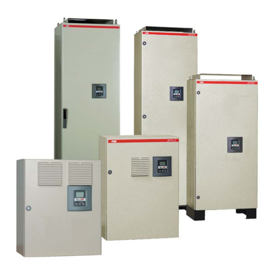
ABB APC Series manual available for free PDF download: Installation, Operation And Maintenance Instructions
ABB APC Series Installation, Operation And Maintenance Instructions (116 pages)
Capacitor Bank
Brand:
ABB
| Category:
Heat Pump
| Size: 3.91 MB
Table of Contents
English
4
Table of Contents
4
1 Read this First
7
About this Instruction Manual
7
Safety
7
APC Types
7
Inspection on Reception
7
Guarantee
8
Storage
8
Handling
8
Electric Insulation Test
8
Figure 1.1. APCM and APCR Setting Upright
8
2 APC Description
9
Figure 2.1. APC Types
9
Figure 2.2. APCL2 of 125Kvar/400V
9
Figure 2.3. APCM2 of 400Kvar/400V
9
Figure 2.4. APCR of 300Kvar/400V
9
Power Modules
10
Ventilation System
10
Figure 2.5. Example of a Front Face and Rear Face (APCM Module)
10
Figure 2.6. Example of a Front Face and Rear Face (APCR Module)
10
Thermistor
11
Temperature Probe
11
Figure 2.7. Temperature Probe
11
3 Installation
12
Location
12
Harmonics
12
Fixation
12
APCL1 and APCL2 Boxes
12
APCM1, APCM2 and APCR Cubicles
12
Connection
12
Figure 3.1. Air Grids and Cable Entry in APCM and APCR
12
Electrical Diagram
13
Connection of Several Banks in Parallel (Master Units or Master Unit + Slave Unit Configuration)
13
Figure 3.2. Electrical Diagram
13
Power Cables Connection
14
APCL1 and APCL2 Boxes
14
Figure 3.3. Connection of Several Banks in Parallel
14
APCM1, APCM2 and APCR Cubicles
15
Current Transformer Connection
15
Figure 3.4. Power Cables Connection to the Incoming Power Terminals for Boxes
15
Figure 3.5. Power Cables Connection to the Incoming Power Terminals for Cubicles
15
Figure 3.6. CT Connection and Release Contact
16
Figure 3.7. Multi Ratio CT
16
Figure 3.8. Summation CT
16
Slave (AUX) to Master (PIL) Unit Connection (for Master Unit + Slave Unit Configuration)
17
Figure 3.9. Slave to Master Unit Connection
17
Master (PIL) APCL2 Wiring
18
Master (PIL) APCM2 Wiring
18
Figure 3.10. Interconnection Cable Location
18
Figure 3.11. Master APCL2 Wiring
18
Master (PIL) APCR Wiring
19
Earth Connection
19
Figure 3.12. Master APCM2 Wiring
19
Figure 3.13. Master APCR Wiring
19
Figure 3.14. Earth Connection
19
4 Easy Commissioning
20
Figure 4.1. View of the AUTO SET Mode in RVC
20
Figure 4.2. View of the Target Cos Φ Setting
21
Figure 4.3. View of the Programmable Parameters
21
Figure 4.4. View of the "Feature" Parameters
21
Figure 4.5. View of the Protections Parameters
22
Front View
23
Figure 4.6. LCD Display of the RVC
23
Rear View
24
Figure 4.7. Rear View of the RVC
24
5 Troubleshooting
25
6 Maintenance
26
APC Maintenance
26
APCR Capacitors Module Replacement
26
Figure 6.1. APCR 300Kvar Module 4 Replacement
26
Figure 6.2. Disconnection of the Contactor and the Protection Fuses
27
Figure 6.3. Removal of the Capacitor Module
27
Access to Reactors
28
Figure 6.4. Access to Reactors
28
Figure 7.1. APC Dimensions and Weights
30
Français
32
1 A Lire en Premier
35
Objectif du Manuel D'instructions
35
Sécurité
35
Présentation
35
Inspection À la Réception du Matériel
35
Garantie
36
Entreposage
36
Manutention
36
Test D'isolation Électrique
36
2 Description de L'apc
37
Modules de Puissance
38
Système de Ventilation
38
Thermistance
39
Sonde de Température
39
3 Installation
40
Emplacement
40
Harmoniques
40
Fixation
40
Coffrets APCL1 Et APCL2
40
Armoires APCM1, APCM2 Et APCR
40
Raccordements
40
Schéma Électrique de Principe
41
Connexion de Plusieurs Batteries en Parallèle (Unités Pilotes Ou Configuration Pilote + Auxiliaire)
41
Raccordement du Circuit de Puissance
42
Coffrets APCL1 Et APCL2
42
Armoires APCM1, APCM2 Et APCR
43
Raccordement du Transformateur D'intensité
43
Connexion de L'unité Auxiliaire (AUX) À L'unité Pilote (PIL) (Pour la Configuration Pilote + Auxiliaire)
45
Connexion À L'unité Pilote (PIL) APCL2
46
Connexion À L'unité Pilote (PIL) APCM2
46
Connexion À L'unité Pilote (PIL) APCR
47
Raccordements À la Terre
47
4 Mise en Service Facile
48
Panneau Frontal
51
Panneau Arrière Et Disposition des Connecteurs
52
5 Détection de Pannes
53
6 Entretien
54
Maintenance de L'apc
54
Remplacement D'un Module de Condensateur de L'apcr
54
Accès Aux Selfs de L'apcr
56
Suomi
60
1 Lue TäMä Ensin
63
Yleistä
63
Turvallisuus
63
APC-Tyypit
63
Vastaanottotarkastus
63
Takuu
63
Säilytys
64
Käsittely
64
Eristystesti
64
Kuva 1.1. APCM Ja APCR Nosto Pystyasentoon
64
2 APC - Kuvaus
65
Kuva 2.1. APC - Kuvaus
65
Kuva 2.2. APCL2, 125Kvar/400V
65
Kuva 2.3. APCM2, 400Kvar/400V
65
Kuva 2.4. APCR, 300Kvar/400V
65
Syöttömoduulit
66
Tuuletusjärjestelmä
66
Kuva 2.5. Kuva Edestä Ja Takaa (APCM-Moduuli)
66
Kuva 2.6. Kuva Edestä Ja Takaa (APCR-Moduuli)
66
Termistori
67
Lämpötila-Anturi
67
Kuva 2.7. Lämpötila-Anturi
67
3 Asennus
68
Asennuspaikka
68
Yliaallot
68
Kiinnitys
68
APCL1- Ja APCL2-Kotelot
68
APCM1-, APCM2- Ja APCR-Kennot
68
Kytkentä
68
Kuva 3.1. Tuuletusritilät Ja Kaapelisyöttö Kennoissa APCM and APCR
68
Periaatekaavio
69
Useampien Paristojen Rinnankytkentä (Isännät Tai Isäntä + Orjasovite)
69
Kuva 3.2. Periaatekaavio
69
Syöttökaapeliliitäntä
70
APCL1- Ja APCL2-Kotelot
70
Kuva 3.3. Useampien Paristojen Rinnankytkentä
70
APCM1, APCM2 Ja APCR Kennot
71
Virtamuuntajaliitäntä
71
Kuva 3.4. Syöttökaapeliliitäntä Syöttöliittimiin (APCL1 Ja APCL2)
71
Kuva 3.5. Syöttökaapeliliitäntä Syöttöliittimiin (APCM Ja APCR)
71
Kuva 3.6. VM Liityntä Ja Laukaisukosketin
72
Kuva 3.7. Usean Muuntosuhteen Virtamuuntaja
72
Kuva 3.8. Summavirtamuuntaja
72
Orja (AUX) Isäntä (PIL) Yksikön Liitäntä (Isäntä-Orjasovite)
73
Kuva 3.9. Orja-Isäntäyksiköiden Liitäntä
73
Isäntä APCL2 Johdotus
74
Isäntä APCM2 Johdotus
74
Kuva 3.10. Yhdyskaapelin Asennus
74
Kuva 3.11. Isäntä APCL2 Johdotus
74
Kuva 3.12. Isäntä APCM2 Johdotus
74
Isäntä APCR Johdotus
75
Maadoitusliitäntä
75
Kuva 3.13. Isäntä APCR Johdotus
75
Kuva 3.14. Maadoitusliitäntä
75
4 Käyttöönotto
76
Kuva 4.1. Automaattisen Asettelun Näyttö RVC :Ssä
76
Kuva 4.2. Tavoitetehokertoimen Asettelu
77
Kuva 4.3. Aseteltujen Parametrien Näyttö
77
Kuva 4.4. 'Ominaisuus' (Feature) Näyttö
77
Näyttö Edestä
79
Kuva 4.6. LCD-Näyttö
79
Näyttö Takaa
80
Kuva 4.7. Näyttö Takaa
80
5 Vianetsintä
81
6 Huolto
82
APC-Pariston Huolto
82
APCR Kondensaattorimoduuleiden Vaihto
82
Kuva 6.1. APCR 300Kvar Moduuli N°4:N Vaihto
82
Kuva 6.2. Kontaktorin Ja Sulakkeiden Irroitus
83
Kuva 6.3. Kondensaattorimoduulin Irroitus
83
Estokelojen Vaihto
84
Kuva 6.4. Estokelojen Vaihto
84
Kuva 7.1. Mitat Ja Painot
86
Svenska
88
1 Läs Detta Först
91
Om den Här Manualen
91
Säkerhet
91
APC-Typer
91
Mottagningsinspektion
91
Garanti
91
Lagring
92
Hantering
92
Test Av den Elektriska Isoleringen
92
2 APC-Beskrivning
93
Effektmoduler
94
Ventilationssystem
94
Termistor
95
Temperatursond
95
3 Installation
96
Plats
96
Övertoner
96
Fastsättning
96
APCL1 Och APCL2
96
Skåpen APCM1, APCM2 Och APCR
96
Anslutning
96
Elschema
97
Anslutning Av Flera Banker Parallellt (Masterenheter Eller Masterenhet + Slavenhet)
97
Kraftkabelanslutning
98
APCL1 Och APCL2
98
Skåpen APCM1, APCM2 Och APCR
99
Transformatoranslutning
99
Anslutning Av Slavenhet (AUX) Till Masterenhet (PIL) (För Konfiguration Med Masterenhet + Slavenhet)
101
Masterkoppling (PIL) Av APCL2
102
Masterkoppling (PIL) Av APCM2
102
Masterkoppling (PIL) Av APCR
103
Jordanslutning
103
4 Enkel Idrifttagning
104
Regulatorn - Vy Framifrån
107
Regulatorn - Vy Bakifrån
108
5 Felsökning
109
6 Underhåll
110
APC-Underhåll
110
Byte Av APCR-Kondensatormodul
110
Åtkomst Till Reaktorer
112
Advertisement
Advertisement
Related Products
ABB APCL1
ABB APCL2
ABB APCM1
ABB APCM2
ABB APCR
ABB AP121/1
ABB AP121/6
ABB AP102
ABB AP10X/1
ABB AP10X/3
ABB Categories
Industrial Equipment
Controller
Measuring Instruments
Battery Charger
DC Drives
More ABB Manuals
Login
Sign In
OR
Sign in with Facebook
Sign in with Google
Upload manual
Upload from disk
Upload from URL