Sign In
Upload
Manuals
Brands
ABB Manuals
Relays
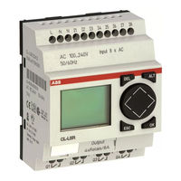
CL-LMR 18AC1 Series
ABB CL-LMR 18AC1 Series Manuals
Manuals and User Guides for ABB CL-LMR 18AC1 Series. We have
1
ABB CL-LMR 18AC1 Series manual available for free PDF download: Applications Manual
ABB CL-LMR 18AC1 Series Applications Manual (296 pages)
Logic relays
Brand:
ABB
| Category:
Relays
| Size: 2.58 MB
Table of Contents
Table of Contents
4
About this Manual
12
Device Designation
12
Reading Conventions
13
1 Logic Relay
14
Intended Users
14
Proper Use
14
Improper Use
14
Overview
15
Device Overview
17
CL Operating Principles
19
Keypad
19
Selecting Menus and Entering Values
19
Selecting Main and System Menu
20
Status Display Logic Relay
21
Status Display for Local Expansion
21
Advanced Status Display
22
CL-LED Display
22
Menu Structure
23
Selecting or Toggling between Menu Items
28
Cursor Display
28
Set Value
28
2 Installation
30
Mounting
30
Connecting the Expansion Device
33
Terminals
34
Tools
34
Cable Cross-Sections
34
Connecting the Power Supply
34
Cable Protection
34
Supplying AC Units
35
Supplying DC Units
36
Connecting the Inputs
38
Connect Digital AC Inputs
38
Connect Digital DC Inputs
43
Connect Analog DC Inputs
44
Connecting High-Speed Counters and Frequency Generators
49
Connecting Outputs
51
Connect Relay Outputs
52
Connecting Transistor Outputs
54
Expanding Inputs/Outputs
57
Local Expansion
57
Remote Expansion
58
3 Commissioning
60
Switching on
60
Setting the Menu Language
61
CL Operating Modes
62
Creating Your First Circuit Diagram
63
Circuit Diagram Display
65
From the First Contact to the Output Coil
66
Wiring
67
Testing the Circuit Diagram
68
Deleting the Circuit Diagram
70
Fast Circuit Diagram Entry
70
4 Wiring with the Logic Relay
72
CL Operation
72
Operating Principles
73
Relays, Function Relays
77
Saving and Loading Circuit Diagrams
79
Working with Contacts and Relays
80
Input and Output Contacts
80
Creating and Modifying Connections
83
Inserting and Deleting a Rung
85
Switching with the Cursor Buttons
85
Checking the Circuit Diagram
87
Coil Functions
88
Function Relays
94
Example Function Relay with Timer and Counter Relay
96
Analog Value Comparator/Threshold Value Switch
101
Circuit Diagram Display with Analog Value Comparator
102
Compatibility of AC010 Devices with Logic Relays
104
Parameter Display in RUN Mode
105
Function of the Analog Value Comparator Function Relay
106
Counters
114
Function of the Counter Function Relay
118
High-Speed Counters, CL-DC1, CL-DC2
122
High-Speed Counters
128
Text Display
134
Wiring a Text Display
135
Scaling
136
Text Entry
137
Entering a Setpoint in a Display
138
Day Time Switch
140
Parameter Display and Parameter Set for 7-Day Time Switch
141
Changing Time Switch Channel
142
Operating Hours Counter
146
Value Range of the Operating Hours Counter
147
Timing Relays
151
Parameter Display and Parameter Set for a Timing Relay
152
Retention
153
Timing Relay Modes
154
Function of the Timing Relay Function Block
157
Examples Timing Relay
164
Jumps
167
Power Flow Display
168
Year Time Switch
170
Parameter Display and Parameter Set for Year Time Switch
171
Changing Time Switch Channel
172
Function of the Year Time Switch
174
Master Reset
177
Operating Modes
178
Basic Circuits
179
Negation (Coil)
180
Parallel Circuit
181
Parallel Circuit Operating Like a Series Connection of N/O Contacts
182
Parallel Circuit Operating Like a Series Connection of N/C Contacts
183
Self-Latching
184
Impulse Relay
185
Cycle Pulse on Falling Edge
186
Circuit Examples
187
X Shift Register
189
Running Light
193
Stairwell Lighting
194
150 CL Settings
198
Password Setup
199
Selecting the Scope of the Password
200
Activating the Password
201
Unlock Logic Relay
202
Changing the Menu Language
204
Changing Parameters
205
Adjustable Parameters for Function Relays
206
Setting Date and Time
208
Setting Summer Time Start and End
209
Selection of Summer Time Start and End
210
Activating Input Delay (Debounce)
217
Activating Debounce (Input Delay)
218
Activating the P Buttons
219
Startup Behaviour
220
Behaviour When the Circuit Diagram Is Deleted
221
Startup Behaviour for Memory Module
222
Setting the Cycle Time
223
Retention (Non-Volatile Data Storage)
224
Setting Retentive Behaviour
225
Deleting Retentive Actual Values
226
Diagram
227
Displaying Device Information
228
6 Inside the Logic Relay
230
CL Operation and Implications for Circuit Diagram Creation
231
Delay Times for Inputs and Outputs
233
Delay Time with CL-AC1 and CL-AC2 Basic Units
235
Delay Times for the Analog Inputs CL-AC1, CL-DC1 and CL-DC2
236
Overload with CL-LST, CL-LMT and CL-LET
237
Expanding CL-LMR/CL-LMT
238
Function Monitoring of Expansion Units
239
Saving and Loading Circuit Diagrams
240
Interface
241
Memory Module
242
Loading or Saving Circuit Diagrams
243
Cl-Soft
246
Logic Relay with Separate Display Module
247
Device Version
248
7 What Happens if
250
Possible Situations When Creating Circuit Diagrams
251
Event
253
Appendix
254
Technical Data
257
Special Approvals
259
Power Supply
260
Inputs
261
Relay Outputs
268
Transistor Outputs
270
List of the Function Relays
273
Available Function Relays
274
Names of Function Relay
275
Compatibility of the Function Relay Parameters
276
Parameter Display 7-Day Time Switch
277
Glossary
278
Index
282
Advertisement
Advertisement
Related Products
ABB CL-LSR 12AC1 Series
ABB CL-LSR 12AC2 Series
ABB CL-LSR 12DC2 Series
ABB CL-LMR 18AC2 Series
ABB CL-LMR 18DC1 Series
ABB CL-LMR 18DC2 Series
ABB CL-LSR 12DC1 Series
ABB CL-LMR.C Series
ABB Busch Watchdog 180 UPComfort II
ABB DCBreak 1815
ABB Categories
Industrial Equipment
Controller
Measuring Instruments
Battery Charger
DC Drives
More ABB Manuals
Login
Sign In
OR
Sign in with Facebook
Sign in with Google
Upload manual
Upload from disk
Upload from URL