Sign In
Upload
Manuals
Brands
ABB Manuals
Water Filtration Systems
PQFM
ABB PQFM Manuals
Manuals and User Guides for ABB PQFM. We have
1
ABB PQFM manual available for free PDF download: Instruction Manual
ABB PQFM Instruction Manual (229 pages)
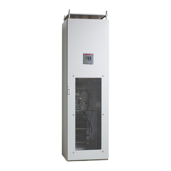
Power Quality Filter
Brand:
ABB
| Category:
Water Filtration Systems
| Size: 7.06 MB
Table of Contents
Table of Contents
2
1 Introduction to this Manual
6
What this Chapter Contains
6
Intended Audience
6
Compatibility
6
Contents
6
Related Publications
7
2 Safety Instructions
8
3 Upon Reception
9
What this Chapter Contains
9
Delivery Inspection
9
Lifting and Transportation Guidelines
9
Identification Tag
11
Storage
11
4 Hardware Description
12
What this Chapter Contains
12
Typical PQFM Filter Panel Layout
12
The PQF Current Generator Hardware
16
The PQF Main Controller
17
The PQF-Manager User Interface
18
Location of the Main PQFM Components
25
Active Filter Components
25
Active Filter Door Components and Protective Grid
30
5 Mechanical Design and Installation
31
What this Chapter Contains
31
Installation Location Requirements
31
Airflow and Cooling Requirements
32
Standard Cubicle Dimensions, Fixing Holes and Clearances
33
Instructions for Mounting IP00 and the PQF-Manager in Cubicles
35
Mechanical Interconnection of PQFM Cubicles
39
Mechanical Preparation of a Common Cable Entry Cubicle
40
6 Electrical Design and Installation
42
What this Chapter Contains
42
Instructions for Connecting the PQF-Manager to an IP00 Filter System
43
Checking the Insulation of the Assembly - Earth Resistance
43
EMC Considerations
43
Earthing Guidelines
45
Selection of the Power Cable Size
47
Selection of the Power Cable Protection/Filter Input Protection Scheme
50
CE Version Protection Scheme
50
Culus Version Protection Scheme
52
Contactor Type for Different Unit Ratings
53
Optional Surge Arrester Circuit (CE Version Only)
53
Connection of the PQFM to the Network
54
Selection of the Current Transformers
56
Current Transformer Installation
59
Basic Rules for Correct CT Installation
59
CT Locations for the Case of Global Compensation - One Feeding Transformer
62
CT Locations for the Case of Individual Compensation - One Feeding Transformer
62
CT Locations for the Case of Two Independent Feeding Transformers
64
CT Locations for the Case of Feeding Transformer and Backup Generator
66
CT Connections for the Case that Plain Capacitors Are Present in the Network
67
CT Connections for the Case that Detuned Capacitor Banks Are Installed Adjacent but
68
Downstream to the Active Filter Cts
68
CT Connections for the Case that Passive Filters and Active Filters Are Installed in the
68
Same Network
68
Electrical Interconnection of PQFM Cubicles and IP00 Plates
69
Mechanical Interconnection
70
Control Board Cable Interconnection
71
Earth Points Interconnection
71
CT Cable Interconnection
72
Connection of the Power Stage to the Supply
72
Electrical Connections to the PQF-Manager User Interface
73
Cabling of Remote Control Functionality
75
Cabling of Alarm Functionality
77
Alarm Outputs
77
Digital Outputs
80
Cabling of Warning Functionality
82
Cabling of the Digital Output Contacts to Monitor Other Filter Operation Modes than Warnings and Alarms
83
Cabling of Main/Auxiliary Control Functionality
83
Implementation of Local Start/Stop Buttons
85
Electrical Connections of Filter Options and Accessories
87
External Communication with PQF
88
Connection of the Modbus Adapter
89
7 The PQF-Manager User Interface
90
What this Chapter Contains
90
PQF-Manager User Interface Description
90
PQF-Manager Overview and Navigation
91
Icons and Main Screen
91
The PQF-Manager Behavior During Filter Initialization
98
The PQF-Manager Locking Facilities
99
The PQF Start, Stop and Fault Acknowledgement Menu
100
The 'Measurements' Menu
102
The 'Overview' Menu
102
The 'System Values' Menu
104
Voltages
104
Line Currents
106
Filter Currents
107
Total Filter Currents
108
Powers
109
Temperatures
109
The 'Min-Max Logging' Menu
110
The 'Settings' Menu
111
The 'Customer Settings' Menu
112
Settings up Harmonics, Reactive Power and Filter Mode
113
Temp Unit
119
Activate Menu
119
Setting up Alarms, Warnings and Digital Inputs and Outputs (D I/O)
120
The 'Commissioning' Menu
122
Setting up the Network Characteristics and the Filter Synchro Mode
123
Setting up the Filter Characteristics
124
Setting up the Current Transformer Ratios and Position
126
Setting up the Filter Rating Parameter
132
Setting up the User's Requirements
133
Commissioning of Temperature Probes
134
The 'Installation Settings' Menu
135
Setting up the 'Standby' Function
136
Setting up the 'Auto Restart' Function
138
Setting up the System Clock
138
Setting Password
139
Installation Locking
139
Set Language
140
The 'PQF Monitoring' Menu
140
The 'Status of Module' Menu
141
The 'Filter Load' Menu
141
The 'Event Logging' Menu
142
The 'Active Warnings' Menu
146
The 'Number of Errors' Menu
146
The 'PQF Operation
147
The 'User Interface Menu
148
Manufacturer Setting
148
About PQF
148
Screen Configuration
149
Communication
150
Modbus RTU
151
MAC Address
153
Ethernet Settings
153
IP Address
157
8 Commissioning Instructions
159
What this Chapter Contains
159
Step 1: Visual and Installation Check
160
Step 2: Setting the Address of each Unit in a Multi-Unit Filter and Terminate the CAN Bus
160
Step 3: Voltage Rating Check/Adaptation and Phase Rotation Check
163
Step 4: Basic Commissioning Parameters Set up (Using PQF-Manager)
164
Step 5: Automatic and Manual CT Detection Procedure
166
Automatic CT Detection Procedure
166
Manual CT Detection Procedure
166
PQF Connection Diagram
167
Material Needed and Hypotheses for Correct Measurements
168
Checking the Correct Connection of the Cts with a Two-Channel Scopemeter
168
Checking the Correct Connection of the Cts with a Fluke 41B
172
Step 6: before Starting the Filter
172
Step 7: Start the Filter
172
Step 8: Generate Filter Load
173
Step 9: Set up the User Requirements
174
Commissioning Report
177
Filter Identification
178
Inspection on Site - Verification of the Active Filter after Installation
179
Programming
180
Testing (with Load)
181
Programmed Parameters
182
Comments
184
9 Operating Instructions
185
What this Chapter Contains
185
Starting and Stopping the Filter
185
Starting the Filter with the PQF-Manager
186
Stopping the Filter with the PQF-Manager
188
Modifying the User Requirements
190
Changing the System Temperature Unit and PQF-Manager Backlighting
191
Consulting Filter Measurements
191
Consulting Filter Statistics and Manufacturer Data
191
Filter Behavior on Fault - Retrieving Error Information
191
10 Maintenance Instructions
194
What this Chapter Contains
194
Maintenance Intervals
194
Standard Maintenance Procedure
195
Step 1: Check the Ambient Temperature Conditions
195
Step 2: Record the Filter Operating Status
195
Step 3: Shut the Filter down
195
Step 4: Inspect and Clean the Filter
196
Step 5: Check the Condition of the Filter Contactors and Fuses
196
Step 6: Check the Tightness of the Electrical and Mechanical Connections
196
Step 7: Correct any Abnormal Conditions Found
196
Step 8: Restart the Filter
196
Fan Replacement
197
DC Capacitor Change
198
DC Capacitor Reforming (V1 Range Only, 208 V £ Ue £ 480 V)
198
Servicing Report
199
Filter Identification
200
Standard Maintenance Procedure
201
Special Service Actions
202
Comments
203
11 Troubleshooting Guide
204
What this Chapter Contains
204
Fault Treatment Procedure
204
Spare Part List for Normal and Dedicated Filter Servicing
208
Troubleshooting Guide
209
Verification of the PQF-Manager Status and the System Leds
209
Fault Tracing
210
12 Technical Specifications
223
What this Chapter Contains
223
Advertisement
Advertisement
Related Products
ABB PQFS
ABB PQFA
ABB PQstorI
ABB PVS-100 Series
ABB PSTB840
ABB SACE PR112-A
ABB SACE PR111-A
ABB PVS-120-TL-3120
ABB PMG-13
ABB PSTB Series
ABB Categories
Industrial Equipment
Controller
Measuring Instruments
Battery Charger
DC Drives
More ABB Manuals
Login
Sign In
OR
Sign in with Facebook
Sign in with Google
Upload manual
Upload from disk
Upload from URL