Sign In
Upload
Manuals
Brands
ABB Manuals
Measuring Instruments
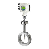
SensyMaster FMT450
ABB SensyMaster FMT450 Manuals
Manuals and User Guides for ABB SensyMaster FMT450. We have
1
ABB SensyMaster FMT450 manual available for free PDF download: Operating Instructions Manual
ABB SensyMaster FMT450 Operating Instructions Manual (160 pages)
Thermal mass flowmeter
Brand:
ABB
| Category:
Measuring Instruments
| Size: 14.77 MB
Table of Contents
Table of Contents
2
1 Safety
4
General Information and Instructions
4
Warnings
4
Intended Use
4
Improper Use
5
Notes on Data Safety
5
Warranty Provisions
5
Manufacturer's Address
5
2 Use in Potentially Explosive Atmospheres
6
Device Overview
6
ATEX / Iecex
6
Cfmus
7
Ex Marking
8
ATEX / Iecex
8
Cfmus
9
Temperature Data
10
Temperature Resistance for the Connecting Cable
10
Environmental and Process Conditions for Model Fmt4Xx
10
Electrical Data
13
Overview
13
Zone 0, 1, 21 and Division 1 - Model: Fmt4Xx-A1, Fmt4Xx-F1
14
Zone 2, 22 and Division 2 - Model: Fmt4Xx-A2, Fmt4Xx-F2
15
Special Connection Conditions
16
Installation Instructions
17
ATEX / Iecex
17
Cfmus
17
Use in Areas Exposed to Combustible Dust
17
Opening and Closing the Housing
17
Cable Entries in Accordance with ATEX / Iecex
18
Cable Entries in Accordance with Cfmus
18
Electrical Connections
19
Process Sealing
19
Operating Instructions
20
Protection against Electrostatic Discharges
20
Devices with Dual-Compartment Housing with Type of Protection Ex 'D' Flameproof (Enclosure)
20
Repair
20
Changing the Type of Protection
21
3 Design and Function
22
Overview
22
Sensor
22
Process Connections
23
Transmitter
24
Device Description
25
Measuring Principle
25
4 Product Identification
26
Name Plate
26
Plates and Symbols
26
5 Transport and Storage
27
Inspection
27
Transport
27
Storing the Device
27
Ambient Conditions
27
Returning Devices
27
6 Installation
28
Safety Instructions
28
Installation Conditions
28
Installation Location and Assembly
28
Inlet and Outlet Sections
29
Installation at High Ambient Temperatures
30
Sensor Insulation
30
Ambient Conditions
30
Ambient Temperature
30
Process Conditions
30
Measured Medium Temperature
30
Material Loads for Process Connections
31
Assembly of the Pipe Component
32
Wafer Type Design (FMT091) and Partial Measuring Section (FMT092)
32
Assembly of the Welding Adapter with Flange or Threaded Connector
34
Welding Adapter with Flange Connector
34
Welding Adapter with Threaded Connection in Accordance with DIN 11851
36
Mounting
37
Assembly of the Welding Adapter with Compression Ring Fitting
38
Mounting
39
Assembly of the Welding Adapter with Hot Tap Fitting
42
Installing the Sensor
43
Wafer Type Design and Welding Adapter
43
Installation / Disassembly in Connection with the Hot Tap Fitting
44
Installing the Transmitter in the Remote Mount Design
46
Opening and Closing the Housing
47
Rotating the Transmitter Housing and LCD Display
48
Installing the Plug-In Cards
50
7 Electrical Connections
54
Safety Instructions
54
Power Supply
54
Cable Entries
55
Installing the Connection Cables
55
Signal Cable
55
Pin Assignment
56
Electrical Data for Inputs and Outputs
57
Connection Examples
62
Connection to Integral Mount Design
64
Connection to Remote Mount Design
66
Transmitter
66
Flowmeter Sensor
68
Digital Communication
69
HART® Communication
69
Modbus® Communication
69
Cable Specification
70
PROFIBUS DP® Communication
70
8 Commissioning
72
Safety Instructions
72
Hardware Settings
72
Dual- Compartment Housing
72
Single-Compartment Housing
73
Configuration of Digital Outputs V1 / V2 or V3 / V4
73
Checks Prior to Commissioning
74
Parameterization of the Device
74
Parameterization Via the Local Operating Interface
74
Parameterization Via the Infrared Service Port Adapter
75
Parameterization Via HART
75
Switching on the Power Supply
75
Parameterization Via the Menu Function Easy Setup
76
9 Operation
81
Safety Instructions
81
Menu Navigation
81
Menu Levels
82
Process Display
83
Switching to the Information Level
83
Error Messages on the LCD Display
84
Switching to the Configuration Level (Parameterization)
84
Selecting and Changing Parameters
85
Parameter Overview
87
Parameter Descriptions
96
Available Units
96
Available Gas Types
97
Available Process Variables
98
Menu: Easy Setup
99
Menu: Device Info
102
Menu: Device Setup
106
Menu: Display
111
Menu: Input/Output
113
Menu: Process Alarm
118
Menu: Communication
119
Menu: Diagnostics
122
Menu: Totalizer
125
Software History
126
Fillmass Batch Function
127
Setup
127
10 Diagnosis / Error Messages
128
Calling up the Error Description
128
General
128
Overview
129
Error Messages
131
Sensorcheck' Diagnosis Function
134
Assessment of the Result
134
11 Maintenance
135
Safety Instructions
135
Sensor
136
Cleaning
136
Cleaning the Sensor Element
136
Integrated Hot Tap Fitting
136
12 Repair
138
Safety Instructions
138
Spare Parts
138
Replacing the Fuse
139
Replacing the LCD Indicator
140
Replacing the Slide-In
141
Integral Mount Design
141
Remote Mount Design
142
Replacing the Sensor
143
Returning Devices
143
13 Dismounting and Disposal
144
Dismounting
144
Disposal
144
14 Specification
145
15 Additional Documents
145
16 Appendix
146
Return Form
146
FMT400 Installation Diagram 3Kxf000094G0009
147
Advertisement
Advertisement
Related Products
ABB FMT200-ECO2
ABB Sensyflow FMT500-IG
ABB Sensyflow FMT400-VTS
ABB Sensyflow FMT400-VTCS
ABB SensyMaster FMT230
ABB SensyMaster FMT250
ABB SensyMaster FMT430
ABB Sensyflow FMT200-D
ABB Sensyflow FMT700-P
ABB FEP515
ABB Categories
Industrial Equipment
Controller
Measuring Instruments
Battery Charger
DC Drives
More ABB Manuals
Login
Sign In
OR
Sign in with Facebook
Sign in with Google
Upload manual
Upload from disk
Upload from URL