Sign In
Upload
Manuals
Brands
Brother Manuals
All in One Printer
DCP-8045DN
Brother DCP-8045DN Manuals
Manuals and User Guides for Brother DCP-8045DN. We have
6
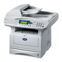
Brother DCP-8045DN manuals available for free PDF download: Service Manual, Parts Reference List, Brochure & Specs
Brother DCP-8045DN Service Manual (367 pages)
Brand:
Brother
| Category:
All in One Printer
| Size: 13.92 MB
Table of Contents
Table of Contents
4
Service Manual
1
Regulation
10
Safety Information
12
Chapter 1 General
14
Overview
14
Specifications
16
General
16
General (Continued)
16
Copy
17
Print Media
17
Fax
18
Printer
19
Scanner
19
Consumable Items
20
Interfaces
20
Network (LAN) Board (NC-9100H)
20
Computer Requirements
21
2.12.1 Type and Size of Paper
22
2.12.2 Recommended Paper
22
2.12.3 Paper Capacity of the Paper Trays
22
Paper
22
2.12.4 Paper Specifications for each Paper Tray
23
2.13.1 Pcl5E/Epson/Ibm Emulation
24
Printable Area
24
2.13.2 PCL6/BR-Script3 Emulation
27
Print Speeds with Various Settings
28
Toner Cartridge Weight Information
29
Serial No. Descriptions
30
Chapter 2 Installation and Basic Operation
32
Conditions Required for Installation
32
Environment
32
Power Supply
32
Unpacking
33
Install the Machine
34
For All Users
34
Install the Automatic Document Feed (ADF) Support
35
Install the Drum Unit Assembly
36
Load Paper into the Paper Tray
37
Release the Scanner Lock
38
For USB Interface Cable Users (for Windows 98/98Se/Me/2000 Professional/Xp)
39
Installing the Driver & Software
39
95/98/98Se/Me/2000 Professional/Xp)
44
For Parallel Interface Cable Users
44
For Windows NT Workstation Version 4.0 Users
49
For Network Interface Cable Users (for Windows ® 95/98/98Se/Me/Nt/2000 Professional/Xp)
51
For USB Interface Cable Users (for Mac os 8.6 to 9.2 Users)
54
For USB Interface Cable Users (for Mac os X 10.1/10.2.1 or Greater Users)
55
For Network Interface Cable Users
56
For Network Interface Cable Users (for Mac os 8.6 to 9.2 Users)
56
OS X 10.1/10.2.1 or Greater Users)
57
Chapter 3 Theory of Operation
58
Electronics
58
General Block Diagram
58
Main PCB Block Diagram
59
Cpu
60
Main PCB
60
Usb
60
Ieee1284
61
Rom
61
Flash ROM
62
Sdram
62
Optional RAM
63
1.3.10 Engine I/O
64
1.3.11 Panel I/O
64
Eeprom
64
Reset Circuit
64
1.3.12 Video I/O
65
1.3.13 Scanner Control
65
1.3.14 Power Supply
66
Engine PCB
67
Low-Voltage Power Supply
68
Power Supply
68
High-Voltage Power Supply
69
Mechanics
70
Overview of Printing Mechanism
70
Scanner Mechanism
71
Paper Registration
72
Paper Supply
72
Paper Transfer
72
Duplex Printing
73
Paper Eject
73
Cover Sensors
74
Sensors
74
Toner Sensors
74
Cassette Sensor / Paper Empty Sensor
75
Paper Eject Sensor
75
Document Cover Sensor
76
MP-PE Sensor
76
Document Front Sensor /Document Rear Sensor
77
DX-Sensor PCB ASSY
77
2.4.10 HP Sensor
78
Rear Cover Sensor
78
Charging
79
Cleaner
79
Drum Unit
79
Photosensitive Drum
79
Primary Charger
79
Print Process
79
Toner Cartridge
79
Transfer Roller
79
Exposure Stage
80
Developing
81
Transfer
81
Fixing Stage
82
Chapter 4 Disassembly and Re-Assembly
83
Safety Precautions
83
Disassembly Flow
84
Disassembly Procedure
85
AC Cord
85
Drum Unit
85
Paper Tray
86
DX Feed ASSY (MFC-8840D/8840DN, DCP-8045D/8045DN Only)
96
Access Cover / Battery
99
Driver PCB Access Cover
100
ADF Unit
101
Document Scanner
110
Panel Unit
115
Rear Cover C (MFC-8440, DCP-8040 Only)
118
Outer Chute (MFC-8440, DCP-8040 Only)
119
Rear Cover MP ASSY / Outer Chute MP ASSY (MFC-8840D/8840DN, DCP-8045D/8045DN Only)
120
Rear Cover L/R
121
Side Cover L/R
122
Joint Cover
123
Front Cover ASSY (MFC-8440, DCP-8040 Only)
128
MP Unit (MFC-8840D/8840DN, DCP-8045D/8045DN Only)
129
Rear Cover Sensor
134
NCU (MFC-8440/8840D/8840DN Only)
135
Fixing Unit
136
Laser Unit
145
Main PCB
147
Base Plate / LV Insulation Sheet
149
DX-Sensor PCB ASSY (MFC-8840D/8840DN, DCP-8045D/8045DN Only)
150
Engine PCB
151
High-Voltage PS PCB ASSY
152
Low-Voltage PS PCB ASSY
153
Paper Feeder
154
Frame L / Drive Unit
161
Reversing Release Solenoid (MFC-8840D/8840DN, DCP-8045D/8045DN Only)
165
Fan Motor 60 Unit LV / Fan Motor 60 Unit
166
Thermistor ASSY
166
Frame R
167
Packing
169
Guidelines for Lead Free Solder
170
Screw Torque List
173
Lubrication
175
Harness Routing
180
Chapter 5 Periodic Maintenance
182
Consumable Parts
182
Drum Unit
182
Toner Cartridge
184
Periodical Replacement Parts
190
Fixing Unit
191
Paper Feeding Kit
199
Periodical Cleaning
203
Cleaning the Machine Exterior
203
Cleaning the Scanner
203
Cleaning the Printer
204
Cleaning the Drum Unit
205
Cleaning the Scanner Window
205
Cleaning the Electrical Terminals
206
Mtbf / Mttr
207
Chapter 6 Troubleshooting
208
Introduction
208
Initial Check
208
Warnings for Maintenance Work
209
Identify the Problem
210
Error Message
211
Error Message on the LCD
211
Error Codes Shown in the "MACHINE ERROR X X" Message
214
Paper Problems
218
Paper Loading Problems
218
Original Is Jammed in the Top of the ADF Unit
219
Original Is Jammed Inside the ADF Unit
219
Original Jams
219
Clearing Jammed Paper
220
Paper Jams
220
Paper Is Jammed in the Duplex Tray (for MFC-8840D/8840DN, DCP-8045D/8045DN)
223
Causes & Countermeasures
224
Paper Feeding Problems
225
Software Setting Problems
227
Malfunctions
230
Troubleshooting of the Control Panel
235
Troubleshooting of Fax Functions
237
Image Defects
241
Diameter of Rollers
241
Image Defect Examples
241
Troubleshooting Image Defect
242
Drum Unit
260
Location of Grounding Contacts
260
Machine Body & Paper Tray
260
Incorrect Printout
261
Network Problem
263
Installation Problem
263
Intermittent Problem
264
TCP/IP Troubleshooting
265
UNIX Troubleshooting
265
Windows
266
Windows 95/98/Me Peer to Peer (HP Jetadmin Compatible Method) Troubleshooting
266
Windows 95/98/Me Peer to Peer Print (LPR) Troubleshooting
266
Windows NT/LAN Server (TCP/IP) Troubleshooting
266
Brother Internet Print (TCP/IP) Troubleshooting
267
Windows 95/98/Me/2000/Xp IPP Troubleshooting
267
10.11 Novell Netware Troubleshooting
268
10.12 Appletalk Troubleshooting
269
10.13 DLC/LLC Troubleshooting
269
Web Browser Troubleshooting (TCP/IP)
269
10.15 Internet Fax Troubleshooting
270
Chapter 7 Maintenance Mode
271
Entry into the Maintenance Mode
271
2. List of Maintenance-Mode Functions
272
List of Maintenance-Mode Functions
272
Detailed Description of Maintenance-Mode Functions
274
EEPROM Parameter Initialization
274
EEPROM Parameter Initialization (Maintenance Mode 01/91)
274
Function Code
274
Printout of Scanning Compensation Data
275
Printout of Scanning Compensation Data (Maintenance Mode 05)
275
ADF Performance Test (Maintenance Mode 08)
277
ADF* Performance Test
277
Placement of CCD Unit in Position for Transportation
277
Placement of CCD Unit in Position for Transportation (Maintenance Mode 06)
277
Test Pattern
278
Test Pattern 1 (Maintenance Mode 09)
278
Firmware Switch Setting (Maintenance Mode 10)
279
Firmware Switch Setting and Printout
279
Printout of Firmware Switch Data
281
Printout of Firmware Switch Data (Maintenance Mode 11)
281
Operation Check of LCD (Maintenance Mode 12)
282
Operational Check of Control Panel PCB
283
Operational Check of Control Panel PCB (Maintenance Mode 13)
283
Sensor Operational Check
284
Sensor Operational Check (Maintenance Mode 32)
284
Received Data Transfer Function
286
Received Data Transfer Function (Maintenance Mode 53)
286
Fine Adjustment of Scan Start/End Positions
288
Fine Adjustment of Scan Start/End Positions (Maintenance Mode 54)
288
CCD Scanner Area Setting
290
CCD Scanner Area Setting (Maintenance Mode 55)
290
EEPROM Customizing
291
EEPROM Customizing (Maintenance Mode 74)
291
Printing out of Machine Log Information
292
Printing out of Machine Log Information (Maintenance Mode 77)
292
Display of the Equipment's Log Information
294
Display of the Equipment's Log Information (Maintenance Mode 80)
294
Machine Error Code Indication
296
Machine Error Code Indication (Maintenance Mode 82)
296
Output of Transmission Log to the Telephone Line
296
Output of Transmission Log to the Telephone Line (Maintenance Mode 87)
296
Cancellation of the Memory Security Mode
297
Cancellation of the Memory Security Mode (Not Applicable to the Japanese Version)
297
Appendix 1 Eeprom Customizing Codes
298
Appendix 2 Installing the Update Data
300
Installing the Update Data to the Machine
300
Connecting the Machine to Your PC
300
Setting up the Machine and Your PC
302
Setting ID Codes to Machines
302
Running the Setup Utility
303
Appendix 3 Firmware Switchs (Wsw)
304
Appendix 3 Firmware Switchs (Wsw
305
WSW01 Dial Pulse Setting
305
WSW02 Tone Signal Setting
306
WSW03 PABX Mode Setting
307
WSW04 TRANSFER Facility Setting
307
WSW05 1St Dial Tone and Busy Tone Detection
308
WSW06 Pause Button Setting and 2Nd Dial Tone Detection
309
Wsw07
311
Wsw08
312
Wsw09
313
Wsw10
314
Wsw11
315
Wsw12
316
Wsw13
317
Wsw14
318
Wsw15
319
Wsw16
320
Wsw17
321
Wsw18
322
Wsw19
323
Wsw20
324
Wsw21
325
Wsw22
325
Wsw23
326
Wsw24
327
Wsw25
327
Wsw26
328
Wsw27
329
Wsw28
330
Wsw29
331
Wsw30
331
Wsw31
332
Wsw32
333
Wsw33
333
Wsw34
334
Wsw35
334
Not Used
334
Appendix
335
Appendix 4 Circuit Diagrams
347
Main PCB Circuit Diagram (1/7
348
Main PCB Circuit Diagram (2/7
348
Main PCB Circuit Diagram (3/7
348
Main PCB Circuit Diagram (4/7
348
Main PCB Circuit Diagram (5/7
348
Main PCB Circuit Diagram (6/7
348
Main PCB Circuit Diagram (7/7
348
Main PCB Circuit Diagram (3/7)
349
Main PCB Circuit Diagram (4/7)
350
Main PCB Circuit Diagram (5/7)
351
Main PCB Circuit Diagram (6/7)
352
Main PCB Circuit Diagram (7/7)
353
Driver PCB Circuit Diagram
354
Engine PCB Circuit Diagram (1/2
355
Engine PCB Circuit Diagram (2/2
356
NCU PCB Circuit Diagram (U.S.A
357
NCU PCB Circuit Diagram (Europe)
358
NCU PCB Circuit Diagram (Asia)
359
NCU PCB Circuit Diagram (Oceania)
360
Control Panel PCB Circuit Diagram
361
Low-Voltage Power Supply PCB Circuit Diagram (200V
362
Low-Voltage Power Supply PCB Circuit Diagram (100V)
363
High-Voltage Power Supply PCB Circuit Diagram (200V
364
High-Voltage Power Supply PCB Circuit Diagram (100V)
365
Appendix 5 Location to Attach the Additional Ribs
366
Advertisement
Brother DCP-8045DN Service Manual (362 pages)
Service Manual
Brand:
Brother
| Category:
All in One Printer
| Size: 11.83 MB
Table of Contents
Table of Contents
4
Service Manual
1
Regulation
10
Safety Information
12
Chapter 1 General
14
Overview
14
Specifications
16
General
16
General (Continued)
16
Copy
17
Print Media
17
Fax
18
Printer
19
Scanner
19
Consumable Items
20
Interfaces
20
Network (LAN) Board (NC-9100H)
20
Computer Requirements
21
2.12.1 Type and Size of Paper
22
2.12.2 Recommended Paper
22
2.12.3 Paper Capacity of the Paper Trays
22
Paper
22
2.12.4 Paper Specifications for each Paper Tray
23
2.13.1 Pcl5E/Epson/Ibm Emulation
24
Printable Area
24
2.13.2 PCL6/BR-Script3 Emulation
27
Print Speeds with Various Settings
28
Toner Cartridge Weight Information
28
Serial No. Descriptions
29
Chapter 2 Installation and Basic Operation
31
Conditions Required for Installation
31
Environment
31
Power Supply
31
Unpacking
32
Install the Machine
33
For All Users
33
Install the Automatic Document Feed (ADF) Support
34
Install the Drum Unit Assembly
35
Load Paper into the Paper Tray
36
Release the Scanner Lock
37
For USB Interface Cable Users (for Windows 98/98Se/Me/2000 Professional/Xp)
38
Installing the Driver & Software
38
95/98/98Se/Me/2000 Professional/Xp)
43
For Parallel Interface Cable Users
43
For Windows NT Workstation Version 4.0 Users
48
For Network Interface Cable Users (for Windows ® 95/98/98Se/Me/Nt/2000 Professional/Xp)
50
For USB Interface Cable Users (for Mac os 8.6 to 9.2 Users)
53
For USB Interface Cable Users (for Mac os X 10.1/10.2.1 or Greater Users)
54
For Network Interface Cable Users
55
For Network Interface Cable Users (for Mac os 8.6 to 9.2 Users)
55
OS X 10.1/10.2.1 or Greater Users)
56
Chapter 3 Theory of Operation
57
Electronics
57
General Block Diagram
57
Main PCB Block Diagram
58
Cpu
59
Main PCB
59
Usb
59
Ieee1284
60
Rom
60
Flash ROM
61
Sdram
61
Optional RAM
62
1.3.10 Engine I/O
63
1.3.11 Panel I/O
63
Eeprom
63
Reset Circuit
63
1.3.12 Video I/O
64
1.3.13 Scanner Control
64
1.3.14 Power Supply
65
Engine PCB
66
Low-Voltage Power Supply
67
Power Supply
67
High-Voltage Power Supply
68
Mechanics
69
Overview of Printing Mechanism
69
Scanner Mechanism
70
Paper Registration
71
Paper Supply
71
Paper Transfer
71
Duplex Printing
72
Paper Eject
72
Cover Sensors
73
Sensors
73
Toner Sensors
73
Cassette Sensor / Paper Empty Sensor
74
Paper Eject Sensor
74
Document Cover Sensor
75
MP-PE Sensor
75
Document Front Sensor /Document Rear Sensor
76
DX-Sensor PCB ASSY
76
2.4.10 HP Sensor
77
Rear Cover Sensor
77
Charging
78
Cleaner
78
Drum Unit
78
Photosensitive Drum
78
Primary Charger
78
Print Process
78
Toner Cartridge
78
Transfer Roller
78
Exposure Stage
79
Developing
80
Transfer
80
Fixing Stage
81
Chapter 4 Disassembly and Re-Assembly
82
Safety Precautions
82
Disassembly Flow
83
Disassembly Procedure
84
AC Cord
84
Drum Unit
84
Paper Tray
85
DX Feed ASSY (MFC-8840D/8840DN, DCP-8045D/8045DN Only)
95
Access Cover / Battery
98
Driver PCB Access Cover
99
ADF Unit
100
Document Scanner
109
Panel Unit
114
Rear Cover C (MFC-8440, DCP-8040 Only)
117
Outer Chute (MFC-8440, DCP-8040 Only)
118
Rear Cover MP ASSY / Outer Chute MP ASSY (MFC-8840D/8840DN, DCP-8045D/8045DN Only)
119
Rear Cover L/R
120
Side Cover L/R
121
Joint Cover
122
Front Cover ASSY (MFC-8440, DCP-8040 Only)
126
MP Unit (MFC-8840D/8840DN, DCP-8045D/8045DN Only)
127
Rear Cover Sensor
132
NCU (MFC-8440/8840D/8840DN Only)
133
Fixing Unit
134
Laser Unit
143
Main PCB
145
Base Plate / LV Insulation Sheet
147
DX-Sensor PCB ASSY (MFC-8840D/8840DN, DCP-8045D/8045DN Only)
148
Engine PCB
149
High-Voltage PS PCB ASSY
150
Low-Voltage PS PCB ASSY
151
Paper Feeder
152
Frame L / Drive Unit
159
Reversing Release Solenoid (MFC-8840D/8840DN, DCP-8045D/8045DN Only)
163
Fan Motor 60 Unit LV / Fan Motor 60 Unit
164
Thermistor ASSY
164
Frame R
165
Packing
167
Guidelines for Lead Free Solder
168
Screw Torque List
171
Lubrication
173
Harness Routing
178
Chapter 5 Periodic Maintenance
180
Consumable Parts
180
Drum Unit
180
Toner Cartridge
182
Periodical Replacement Parts
186
Fixing Unit
187
Paper Feeding Kit
195
Periodical Cleaning
199
Cleaning the Machine Exterior
199
Cleaning the Scanner
199
Cleaning the Printer
200
Cleaning the Drum Unit
201
Cleaning the Scanner Window
201
Cleaning the Electrical Terminals
202
Mtbf / Mttr
203
Chapter 6 Troubleshooting
204
Introduction
204
Initial Check
204
Warnings for Maintenance Work
205
Identify the Problem
206
Error Message
207
Error Message on the LCD
207
Error Codes Shown in the "MACHINE ERROR X X" Message
210
Paper Problems
214
Paper Loading Problems
214
Original Is Jammed in the Top of the ADF Unit
215
Original Is Jammed Inside the ADF Unit
215
Original Jams
215
Clearing Jammed Paper
216
Paper Jams
216
Paper Is Jammed in the Duplex Tray (for MFC-8840D/8840DN, DCP-8045D/8045DN)
219
Causes & Countermeasures
220
Paper Feeding Problems
221
Software Setting Problems
223
Malfunctions
226
Troubleshooting of the Control Panel
231
Troubleshooting of Fax Functions
233
Image Defects
237
Diameter of Rollers
237
Image Defect Examples
237
Troubleshooting Image Defect
238
Drum Unit
256
Location of Grounding Contacts
256
Machine Body & Paper Tray
256
Incorrect Printout
257
Network Problem
259
Installation Problem
259
Intermittent Problem
260
TCP/IP Troubleshooting
261
UNIX Troubleshooting
261
Windows
262
Windows 95/98/Me Peer to Peer (HP Jetadmin Compatible Method) Troubleshooting
262
Windows 95/98/Me Peer to Peer Print (LPR) Troubleshooting
262
Windows NT/LAN Server (TCP/IP) Troubleshooting
262
Brother Internet Print (TCP/IP) Troubleshooting
263
Windows 95/98/Me/2000/Xp IPP Troubleshooting
263
10.11 Novell Netware Troubleshooting
264
10.12 Appletalk Troubleshooting
265
10.13 DLC/LLC Troubleshooting
265
Web Browser Troubleshooting (TCP/IP)
265
10.15 Internet Fax Troubleshooting
266
Chapter 7 Maintenance Mode
267
Entry into the Maintenance Mode
267
2. List of Maintenance-Mode Functions
268
List of Maintenance-Mode Functions
268
Detailed Description of Maintenance-Mode Functions
270
EEPROM Parameter Initialization
270
EEPROM Parameter Initialization (Maintenance Mode 01/91)
270
Function Code
270
Printout of Scanning Compensation Data
271
Printout of Scanning Compensation Data (Maintenance Mode 05)
271
ADF Performance Test (Maintenance Mode 08)
273
ADF* Performance Test
273
Placement of CCD Unit in Position for Transportation
273
Placement of CCD Unit in Position for Transportation (Maintenance Mode 06)
273
Test Pattern
274
Test Pattern 1 (Maintenance Mode 09)
274
Firmware Switch Setting (Maintenance Mode 10)
275
Firmware Switch Setting and Printout
275
Printout of Firmware Switch Data
277
Printout of Firmware Switch Data (Maintenance Mode 11)
277
Operation Check of LCD (Maintenance Mode 12)
278
Operational Check of Control Panel PCB
279
Operational Check of Control Panel PCB (Maintenance Mode 13)
279
Sensor Operational Check
280
Sensor Operational Check (Maintenance Mode 32)
280
Received Data Transfer Function
282
Received Data Transfer Function (Maintenance Mode 53)
282
Fine Adjustment of Scan Start/End Positions
284
Fine Adjustment of Scan Start/End Positions (Maintenance Mode 54)
284
CCD Scanner Area Setting
286
CCD Scanner Area Setting (Maintenance Mode 55)
286
EEPROM Customizing
287
EEPROM Customizing (Maintenance Mode 74)
287
Printing out of Machine Log Information
288
Printing out of Machine Log Information (Maintenance Mode 77)
288
Display of the Equipment's Log Information
290
Display of the Equipment's Log Information (Maintenance Mode 80)
290
Machine Error Code Indication
292
Machine Error Code Indication (Maintenance Mode 82)
292
Output of Transmission Log to the Telephone Line
292
Output of Transmission Log to the Telephone Line (Maintenance Mode 87)
292
Cancellation of the Memory Security Mode
293
Cancellation of the Memory Security Mode (Not Applicable to the Japanese Version)
293
Appendix 1 Eeprom Customizing Codes
294
Appendix 2 Installing the Update Data
296
Installing the Update Data to the Machine
296
Connecting the Machine to Your PC
296
Setting up the Machine and Your PC
298
Setting ID Codes to Machines
298
Running the Setup Utility
299
Appendix 3 Firmware Switchs (Wsw)
300
Appendix 3 Firmware Switchs (Wsw
301
WSW01 Dial Pulse Setting
301
WSW02 Tone Signal Setting
302
WSW03 PABX Mode Setting
303
WSW04 TRANSFER Facility Setting
303
WSW05 1St Dial Tone and Busy Tone Detection
304
WSW06 Pause Button Setting and 2Nd Dial Tone Detection
305
Wsw07
307
Wsw08
308
Wsw09
309
Wsw10
310
Wsw11
311
Wsw12
312
Wsw13
313
Wsw14
314
Wsw15
315
Wsw16
316
Wsw17
317
Wsw18
318
Wsw19
319
Wsw20
320
Wsw21
321
Wsw22
321
Wsw23
322
Wsw24
323
Wsw25
323
Wsw26
324
Wsw27
325
Wsw28
326
Wsw29
327
Wsw30
327
Wsw31
328
Wsw32
329
Wsw33
329
Wsw34
330
Wsw35
330
Wsw36
331
Wsw37
332
Wsw38
333
Wsw39
334
Wsw40
335
Wsw41
336
Wsw42
337
Wsw43
338
Wsw44
339
Wsw45
340
Not Used
340
Appendix 4 Circuit Diagrams
343
Main PCB Circuit Diagram (1/7
343
Main PCB Circuit Diagram (2/7)
344
Main PCB Circuit Diagram (3/7)
345
Main PCB Circuit Diagram (4/7)
346
Main PCB Circuit Diagram (5/7)
347
Main PCB Circuit Diagram (6/7)
348
Main PCB Circuit Diagram (7/7)
349
Driver PCB Circuit Diagram
350
Engine PCB Circuit Diagram (1/2
351
Engine PCB Circuit Diagram (2/2
352
NCU PCB Circuit Diagram (U.S.A
353
NCU PCB Circuit Diagram (Europe)
354
NCU PCB Circuit Diagram (Asia)
355
NCU PCB Circuit Diagram (Oceania)
356
Control Panel PCB Circuit Diagram
357
Low-Voltage Power Supply PCB Circuit Diagram (200V
358
Low-Voltage Power Supply PCB Circuit Diagram (100V)
359
High-Voltage Power Supply PCB Circuit Diagram (200V
360
High-Voltage Power Supply PCB Circuit Diagram (100V)
361
Brother DCP-8045DN Service Manual (361 pages)
Brand:
Brother
| Category:
All in One Printer
| Size: 26.74 MB
Table of Contents
Table of Contents
4
Regulation
10
Safety Information
12
Chapter 1 General
14
Overview
14
Specifications
16
General
16
General (Continued)
16
Print Media
17
Copy
17
Scanner
19
Printer
19
Interfaces
20
Consumable Items
20
Network (LAN) Board (NC-9100H)
20
Computer Requirements
21
Paper
22
2.12.1 Type and Size of Paper
22
2.12.2 Recommended Paper
22
2.12.3 Paper Capacity of the Paper Trays
22
2.12.4 Paper Specifications for each Paper Tray
23
Printable Area
24
2.13.1 Pcl5E/Epson/Ibm Emulation
24
2.13.2 PCL6/BR-Script3 Emulation
27
Print Speeds with Various Settings
28
Toner Cartridge Weight Information
28
Serial No. Descriptions
29
Chapter 2 Installation and Basic Operation
31
Conditions Required for Installation
31
Power Supply
31
Environment
31
Unpacking
32
Install the Machine
33
For All Users
33
Install the Automatic Document Feed (ADF) Support
34
Install the Drum Unit Assembly
35
Load Paper into the Paper Tray
36
Release the Scanner Lock
37
Installing the Driver & Software
38
For USB Interface Cable Users (for Windows 98/98Se/Me/2000 Professional/Xp)
38
For Parallel Interface Cable Users (for Windows ® 95/98/98Se/Me/2000 Professional/Xp)
43
For Windows NT
48
Workstation Version 4.0 Users
48
For Network Interface Cable Users (for Windows ® 95/98/98Se/Me/Nt/2000 Professional/Xp)
50
For USB Interface Cable Users (for Mac os 8.6 to 9.2 Users)
53
For USB Interface Cable Users (for Mac os X 10.1/10.2.1 or Greater Users)
54
For Network Interface Cable Users (for Mac os 8.6 to 9.2 Users)
55
For Network Interface Cable Users (for Mac os X 10.1/10.2.1 or Greater Users)
56
Chapter 3 Theory of Operation
57
Electronics
57
General Block Diagram
57
Main PCB Block Diagram
58
Main PCB
59
Cpu
59
Usb
59
Ieee1284
60
Rom
60
Flash ROM
61
Sdram
61
Optional RAM
62
Eeprom
63
Reset Circuit
63
1.3.10 Engine I/O
63
1.3.11 Panel I/O
63
1.3.12 Video I/O
64
1.3.13 Scanner Control
64
Power Supply
66
Engine PCB
66
Power Supply
67
Low-Voltage Power Supply
67
High-Voltage Power Supply
68
Mechanics
69
Overview of Printing Mechanism
69
Scanner Mechanism
70
Paper Transfer
71
Paper Supply
71
Paper Registration
71
Paper Eject
72
Duplex Printing
72
Sensors
73
Cover Sensors
73
Toner Sensors
73
Cassette Sensor / Paper Empty Sensor
74
Paper Eject Sensor
74
MP-PE Sensor
75
Document Cover Sensor
75
Document Front Sensor /Document Rear Sensor
76
DX-Sensor PCB ASSY
76
Rear Cover Sensor
77
2.4.10 HP Sensor
77
Drum Unit
78
Photosensitive Drum
78
Primary Charger
78
Transfer Roller
78
Cleaner
78
Toner Cartridge
78
Print Process
78
Charging
78
Exposure Stage
79
Developing
80
Transfer
80
Fixing Stage
81
Chapter 4 Disassembly and Re-Assembly
82
Safety Precautions
82
Disassembly Flow
83
Disassembly Procedure
84
AC Cord
84
Drum Unit
84
Paper Tray
85
DX Feed ASSY (MFC-8840D/8840DN, DCP-8045D/8045DN Only)
95
Access Cover / Battery
98
Driver PCB Access Cover
99
ADF Unit
100
Document Scanner
109
Panel Unit
114
Rear Cover C (MFC-8440, DCP-8040 Only)
117
Outer Chute (MFC-8440, DCP-8040 Only)
118
Rear Cover MP ASSY / Outer Chute MP ASSY (MFC-8840D/8840DN, DCP-8045D/8045DN Only)
119
Rear Cover L/R
120
Side Cover L/R
121
Joint Cover
122
Front Cover ASSY (MFC-8440, DCP-8040 Only)
126
MP Unit (MFC-8840D/8840DN, DCP-8045D/8045DN Only)
127
Rear Cover Sensor
132
NCU (MFC-8440/8840D/8840DN Only)
133
Fixing Unit
134
Laser Unit
143
Main PCB
145
Base Plate / LV Insulation Sheet
147
DX-Sensor PCB ASSY (MFC-8840D/8840DN, DCP-8045D/8045DN Only)
148
Engine PCB
149
High-Voltage PS PCB ASSY
150
Low-Voltage PS PCB ASSY
151
Paper Feeder
152
Frame L / Drive Unit
159
Reversing Release Solenoid (MFC-8840D/8840DN, DCP-8045D/8045DN Only)
163
Thermistor ASSY
164
Fan Motor 60 Unit LV / Fan Motor 60 Unit
164
Frame R
165
Packing
167
Guidelines for Lead Free Solder
168
Screw Torque List
171
Lubrication
173
Harness Routing
178
Chapter 5 Periodic Maintenance
180
Consumable Parts
180
Drum Unit
180
Toner Cartridge
182
Periodical Replacement Parts
186
Fixing Unit
187
Paper Feeding Kit
195
Periodical Cleaning
199
Cleaning the Machine Exterior
199
Cleaning the Scanner
199
Cleaning the Printer
200
Cleaning the Drum Unit
201
Cleaning the Scanner Window
201
Cleaning the Electrical Terminals
202
Mtbf / Mttr
203
Chapter 6 Troubleshooting
204
Introduction
204
Initial Check
204
Warnings for Maintenance Work
205
Identify the Problem
206
Error Message
207
Error Message on the LCD
207
Error Codes Shown in the "MACHINE ERROR X X" Message
210
Paper Problems
214
Paper Loading Problems
214
Original Jams
215
Original Is Jammed in the Top of the ADF Unit
215
Original Is Jammed Inside the ADF Unit
215
Paper Jams
216
Clearing Jammed Paper
216
Paper Is Jammed in the Duplex Tray (for MFC-8840D/8840DN, DCP-8045D/8045DN)
219
Causes & Countermeasures
220
Paper Feeding Problems
221
Software Setting Problems
223
Malfunctions
226
Troubleshooting of the Control Panel
231
Troubleshooting of Fax Functions
233
Image Defects
237
Image Defect Examples
237
Diameter of Rollers
237
Troubleshooting Image Defect
238
Location of Grounding Contacts
256
Drum Unit
256
Machine Body & Paper Tray
256
Incorrect Printout
257
Network Problem
259
Installation Problem
259
Intermittent Problem
260
TCP/IP Troubleshooting
261
UNIX Troubleshooting
261
Windows ® NT/LAN Server (TCP/IP) Troubleshooting
262
Windows ® 95/98/Me Peer to Peer Print (LPR) Troubleshooting
262
Windows 95/98/Me Peer to Peer (HP Jetadmin Compatible Method) Troubleshooting
262
Brother Internet Print (TCP/IP) Troubleshooting
263
Windows 95/98/Me/2000/Xp IPP Troubleshooting
263
10.11 Novell Netware Troubleshooting
264
10.12 Appletalk Troubleshooting
265
10.13 DLC/LLC Troubleshooting
265
Web Browser Troubleshooting (TCP/IP)
265
10.15 Internet Fax Troubleshooting
266
Chapter 7 Maintenance Mode
267
Entry into the Maintenance Mode
267
List of Maintenance-Mode Functions
268
Detailed Description of Maintenance-Mode Functions
270
EEPROM Parameter Initialization (Maintenance Mode 01/91)
270
Printout of Scanning Compensation Data (Maintenance Mode 05)
271
Placement of CCD Unit in Position for Transportation (Maintenance Mode 06)
273
ADF Performance Test (Maintenance Mode 08)
273
Test Pattern 1 (Maintenance Mode 09)
274
Firmware Switch Setting and Printout
275
Firmware Switch Setting (Maintenance Mode 10)
275
Printout of Firmware Switch Data (Maintenance Mode 11)
277
Operation Check of LCD (Maintenance Mode 12)
278
Operational Check of Control Panel PCB (Maintenance Mode 13)
279
Received Data Transfer Function (Maintenance Mode 53)
282
Fine Adjustment of Scan Start/End Positions (Maintenance Mode 54)
284
CCD Scanner Area Setting (Maintenance Mode 55)
286
EEPROM Customizing (Maintenance Mode 74)
287
Printing out of Machine Log Information (Maintenance Mode 77)
288
Display of the Equipment's Log Information (Maintenance Mode 80)
290
Machine Error Code Indication (Maintenance Mode 82)
292
Output of Transmission Log to the Telephone Line (Maintenance Mode 87)
292
Cancellation of the Memory Security Mode (Not Applicable to the Japanese Version)
293
Appendix 1 Eeprom Customizing Codes
294
Appendix 2 Installing the Update Data
296
Installing the Update Data to the Machine
296
Connecting the Machine to Your PC
298
Setting up the Machine and Your PC
298
Setting ID Codes to Machines
298
Running the Setup Utility
299
Appendix 3 Firmware Switchs (Wsw)
300
Appendix 3 Firmware Switchs (Wsw
301
WSW01 Dial Pulse Setting
301
WSW 02 Tone Signal Setting
302
WSW 03 PABX Mode Setting
303
WSW 04 TRANSFER Facility Setting
303
WSW 05 1St Dial Tone and Busy Tone Detection
304
WSW06 Pause Button Setting and 2Nd Dial Tone Detection
305
Wsw07
307
Wsw08
308
Wsw09
309
Wsw10
310
WSW11 Busy Tone Setting
311
WSW 12 Signal Detection Condition Setting
312
WSW13 Modem Setting
313
WSW 14 AUTO ANS Facility Setting
314
WSW 15 REDIAL Facility Setting
315
Wsw16
316
Wsw17
317
Wsw18
318
WSW 19 Transmission Speed Setting
319
WSW 20 Overseas Communications Mode Setting
320
Wsw21
321
WSW22 ECM Setting
321
WSW23 Communications Setting
322
Wsw24
323
Wsw25
323
Wsw28
326
Wsw29
327
Wsw30
327
Wsw31
328
Wsw32
329
Wsw33
329
Wsw34
330
Wsw35
330
Wsw36
331
Wsw37
332
Wsw40
335
Wsw41
336
Wsw42
337
Wsw43
338
Speeding up Scanning-1
339
Speeding up Scanning-2
340
Wsw47
341
Wsw48
342
Wsw49
342
Wsw50
342
Appendix 4 Circuit Diagrams
343
Main PCB Circuit Diagram (2/7
344
Main PCB Circuit Diagram (3/7
345
Main PCB Circuit Diagram (4/7
346
Main PCB Circuit Diagram (5/7
347
Main PCB Circuit Diagram (6/7
348
Main PCB Circuit Diagram (7/7
349
Driver PCB Circuit Diagram
350
Engine PCB Circuit Diagram (1/2
351
Engine PCB Circuit Diagram (2/2
352
NCU PCB Circuit Diagram (U.S.A
353
NCU PCB Circuit Diagram (Europe
354
Control Panel PCB Circuit Diagram
357
Low-Voltage Power Supply PCB Circuit Diagram (200V
358
High-Voltage Power Supply PCB Circuit Diagram (200V
360
Advertisement
Brother DCP-8045DN Parts Reference List (36 pages)
Facsimile Parts Reference List
Brand:
Brother
| Category:
All in One Printer
| Size: 1.75 MB
Brother DCP-8045DN Service Manual (12 pages)
Brand:
Brother
| Category:
All in One Printer
| Size: 0.28 MB
Table of Contents
Service Manual
1
Chapter 3 Theory of Operation
4
Chapter 5 Periodic Maintenance
6
Brother DCP-8045DN Brochure & Specs (2 pages)
Brother Laser Printer Brochure
Brand:
Brother
| Category:
All in One Printer
| Size: 6.28 MB
Advertisement
Related Products
Brother DCP-8045D
Brother DCP-8040
Brother DCP 8040 - B/W Laser - All-in-One
Brother DCP-8040D
Brother DCP-8025DN - Laser - All-in-One
Brother DCP 8060
Brother DCP-8070D
Brother DCP-8080DN
Brother DCP 8080D
Brother DCP-8085
Brother Categories
Sewing Machine
All in One Printer
Printer
Label Maker
Fax Machine
More Brother Manuals
Login
Sign In
OR
Sign in with Facebook
Sign in with Google
Upload manual
Upload from disk
Upload from URL