Sign In
Upload
Manuals
Brands
Brother Manuals
Printer
HL-L6402DW
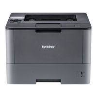
Brother HL-L6402DW Laser Mono Printer Manuals
Manuals and User Guides for Brother HL-L6402DW Laser Mono Printer. We have
2
Brother HL-L6402DW Laser Mono Printer manuals available for free PDF download: Technical Reference Manual, Service Manual
Brother HL-L6402DW Technical Reference Manual (517 pages)
Brand:
Brother
| Category:
Printer
| Size: 2.26 MB
Table of Contents
Table of Contents
5
About the Manual
16
Chapter 1 Introduction
17
About the Manual
17
Areas of Use
18
Font Development
19
Chapter 2 Pcl
21
Command List
21
Introduction
22
Command List
26
Introduction
29
Controlling the Printer
30
Control Codes
30
Escape Sequences
31
Line Termination
31
Display Functions Mode
32
End-Of-Line Wrap
32
Environments
33
Factory Default Environment
33
Macro Overlay Environment
33
Modified Print Environment
33
User Default Environment
33
Job Control
34
Commands
34
Page Size
34
Media Type Selection
39
Output Tray
40
Paper Source
41
Left Long-Edge Offset Registration
45
Top Offset Registration
45
Job Separation Command
46
Paper Side Selection
46
Reset
46
Simplex/Duplex Printing
46
Change Emulation Mode
48
Exit Current Emulation Mode
48
Printer Self Test
48
Reset to Factory Default Settings
48
Reset to User Settings
48
The Page
50
HP-GL/2 Graphics Window
50
Logical Page
50
Physical Page
50
Printable Area
50
Text Area
50
Portrait
51
Landscape
53
Coordinates
55
Setting the Left and Right Margins
55
Unit of Measure
55
Units
55
Resetting the Horizontal Margins
56
Setting the Top Margin
56
Setting the Horizontal Motion Index (HMI)
57
Setting the Vertical Motion Index (VMI)
57
Setting Line Spacing
58
Text Length
58
Page Length
59
Perforation Skip
59
Positioning the Cursor
60
Vertical Positioning
60
Horizontal Position
61
Positioning the Cursor Using Control Codes
62
Using the Cursor Position Stack
62
Half Line Feed
63
Logical
63
Text Direction
63
Using Fonts
65
Introduction
65
Bitmap Fonts
65
Font Types
65
Scalable Fonts
65
Bound Fonts
67
Card/Cartridge Fonts
67
Downloadable Fonts
67
Font Sources
67
Internal Fonts
67
Primary and Secondary Fonts
67
Specifying the Primary Font
67
Specifying the Secondary Font
67
Unbound Fonts
67
Selecting the Default Fonts
68
Switching between the Primary and Secondary Fonts
68
Criteria for Font Selection
69
Height
69
Pitch
69
Style
69
Symbol Collections
69
Symbol Set
69
Type of Character Spacing
69
Stroke Weight
70
Typeface
70
Font Selection Commands
71
Define Symbol Set
71
Symbol Set ID Code Command
71
User-Defined Symbol Sets
71
Selecting the Symbol Set
73
Symbol Set Control Command
73
Selecting the Pitch
75
Selecting the Type of Character Spacing
75
Scaling the Scalable Fonts Vertically or Horizontally
76
Selecting the Height
76
Selecting the Style
76
Selecting the Stroke Weight
77
Selecting the Typeface
77
Font Orientation
78
Esc&D#D (27)(38)(100)#(68) <1Bh><26H><64H>#<44H
79
Transparent Print Data
79
Downloadable Font Manipulation
80
Font ID
80
Operations on Downloaded Fonts
80
Selecting a Downloaded Font
80
Creating Downloadable Fonts
81
Downloading
81
Sending the Font Descriptor
81
Unicode Symbol Index Character Complement Bits
92
Sending a Character Code
93
Sending a Character Descriptor and Data
93
Using Graphics
99
Source, Pattern and Destination
99
Set Source Transparency
99
Set Pattern Transparency
100
Set Area Fill Identity
101
Set Pattern Reference Point
102
User-Defined Pattern Command
102
Set Pattern Type
103
User-Defined Pattern Control
103
Plotting Rectangles
105
Cursor Position
105
Draw Filled Rectangle
105
Set Rectangle Height
105
Set Rectangle Width
105
Raster Graphics
107
Positioning the Cursor
107
Set High Resolution Control
107
Set Raster Image Orientation
107
Set Raster Resolution
107
Set Compression Mode
108
Set Raster Area Height
108
Set Raster Area Width
108
Set Raster Y-Offset
108
Compress Transfer Graphics
114
End Raster Transfer
114
Send Raster Data
114
Start Raster Transfer
114
Horizontal 1200-Dpi Image Format Mode (Raster Graphic Mode 1027)
116
Vector Graphics
118
Enter HP-GL/2 Mode
118
The Picture Frame
119
Set Picture Frame Anchor Point
119
Set Picture Frame Horizontal Size
119
Set Picture Frame Vertical Size
119
Specify Horizontal Plot Size
119
Specify Vertical Plot Size
119
The Default Picture Frame
119
Macros
120
The Purpose of a Macro
120
Macro ID
120
Defining a Macro
121
End Macro Definition
121
Running a Macro
122
Call Macro
122
Disable Macro for Overlay
122
Enable Macro for Overlay
122
Execute Macro
122
Handling Macros
123
Delete All Macros
123
Delete All Macros from the Storage Device
123
Delete All Temporary Macros
123
Delete Macro
123
Delete Macro from the Storage Device
123
Make Macro Permanent
123
Make Macro Temporary
123
Save Macro into the Storage Device
123
Appletalk Configuration
124
Execute Data
124
MIO Video I/O Port Control
125
Status Readback
126
Introduction
126
Memory Status Request
126
Entity Status
126
Status Response
126
Status Response Syntax
127
Set Status Readback Location Type
127
Set Status Readback Location Unit
127
Entity Status Response
128
Font Response
128
Inquire Status Readback Entity
128
Bitmap Fonts
129
Bound Scalable Fonts
129
Download Fonts
129
Location Type 1 (Currently Selected) Font
129
Unbound Scalable Fonts
129
Font Extended Response
130
Macro Response
131
Use-Defined Pattern Response
131
Symbol Set Response
131
Entity Error Codes
132
Free Space Command
132
Echo Command
133
Index
134
Flush All Pages Command
133
Font Cache
133
Memory Error Response
133
Memory Status Response
133
Chapter 3 Pcl5C
138
Chapter 5 Pjl Printer Job Language
138
Introduction
138
Introduction
139
Color Modes
140
Using Simple Color Mode - Set Simple Color
140
Using PCL Color Mode - Set PCL Color Setting
141
Using HP-GL/2 Color Mode
145
Color Palettes
146
Set Color to Palette
146
Push/Pop Palette
147
Select Color
147
Color Graphics
148
Set Destination Raster Height
148
Set Destination Raster Width
148
Start Raster Transfer
148
Enter HP-GL/2 Mode
149
Send Raster Data by Plane
149
Set Scale Algorithm
149
Enhance Output
150
Set Monochrome Mode
150
Set Render Algorithm
150
Download Dither Matrix
151
Set Gamma Correction
151
User-Defined Pattern Command
151
IN (Initialize Set Instruction) Command
152
PC (Pen Color) Command
152
Chapter 2 Pcl Printer Control Language
152
Hp-Gl/2
152
NP (Number of Pens) Command
153
CR (Color Range) Command
153
Index
154
Chapter 4 Hp-Gl/2
156
Introduction
156
Command List
158
Introduction
160
Terminology
161
Picture Frame
161
Anchor Point
161
Graphics Window
161
Hard Clip Limits
161
Soft Clip Limits
161
Graphics Units
161
User Units
161
Current Units
161
Pens
161
Absolute and Relative Plotting
162
Fills
162
Command Syntax
163
Mnemonic
163
Parameters
163
Separators
163
Terminator
163
The Hp-Gl Graphics Window
164
Units
164
The Scaling Points P1 and P2
164
Scaling
164
Transformation
164
Preparing to Print Graphic Images
165
Setting up the Graphics Window
165
Using Existing Image Plots
165
Printing an Image
165
Entering HP-GL/2 Mode
165
Quitting HP-GL/2 Mode
165
Commands
166
Initialize Commands
166
Plot Area and Unit Setting Instructions
168
Pen Control and Plot Instructions
172
The Polygon Group
179
Plot Function Instructions
184
Index
185
Character Plot Instructions
192
Introduction
193
Index
206
Chapter 5 Pjl
209
Introduction
211
About PJL
211
In Case of Using PJL with a Non-PJL Printer
212
Other Printer Languages
212
PCL Jobs
212
Postscript Jobs
212
PJL Syntax and Format
213
Alphanumeric Variables
214
Invalid Commands
214
Numeric Variables
214
Strings
214
Syntax Errors
214
Syntax Warning and Semantic Warning
214
Variables
214
How to Use Pjl
215
Overview
215
PJL Job Requirement
215
Command Group
216
Kernel Commands
217
EXECUTE Command
217
Introduction
217
UEL Command
217
COMMENT Command
218
ENTER Command
218
Context Switching
219
Explicit Switching
219
Implicit Switching
219
Printer Language Switching
219
Job Separation Commands
220
Introduction
220
JOB Command
220
EOJ Command
221
Environment Commands
222
Introduction
222
Print Environment
222
PJL Reset Conditions
223
Remember These Points about Environments
223
L5102Dw/L5100Dn(T)/5590Dn/L5200Dw(T)/L5202Dw/L6200Dw(T)/L6202Dw/L6250Dn/L6250Dw/L6300 Dw(T)/L6400Dw(T)/L6402Dw
225
Variables
225
1660E/2060/2400C/2400Ce/3400Cn/2600Cn/3450Cn/2700Cn/4040Cn/4050Cdn/4070Cdw/3040Cn/3045 CN/3070CW/3075CW
256
Default Command
261
Initialize Command
261
Reset Command
262
Set Command
262
Status Readback Commands
264
Basic Format of Status Readback Responses
264
Introduction
264
Synchronization with the Printer
264
Inquire Command
265
DINQUIRE Command
266
ECHO Command
267
INFO Command
268
CONFIG Category
270
ID Category
270
MEMORY Category
272
STATUS Category
273
VARIABLES Category
273
USTATUS Category
275
USTATUS Command
276
Device Variable
277
JOB Variables
278
PAGE Variable
279
TIMED Variable
279
JOB Recovery
280
USTATUSOFF Command
280
Device Attendance Commands
281
Introduction
281
RDYMSG Command
281
OPMSG Command
282
STMSG Command
282
Index
284
Chapter 6 Epson Fx
285
Chapter 6 Epson Fx-850
286
Command List
287
Introduction
289
Emulation Details
290
Ignored Commands
290
Resolution
290
Terminology
291
Conventions
291
Syntax
291
Control Codes
292
Escape Sequence
292
The Control Panel
292
Commands
293
Basic Printer Operations
293
Page Set up
297
Line Spacing
299
Using Tabs
300
Using Standard Characters
301
Using Customized Characters
307
Index
312
Chapter 7 Ibm Proprinter Xl
313
Chapter 7 Ibm Proprinter Xl
314
Command List
314
Command List
315
Introduction
317
Emulation Details
318
Character Set Selection
318
Control Codes
318
Controlling the Printer
318
Escape Sequences
318
Ignored Commands
318
Resolution
318
Notation Used in this Emulation Description
319
Data Conventions
319
Syntax
319
Commands
320
Basic Printer Operation
320
Page Format
323
Index
333
Chapter 8 Bar Code Control
334
Chapter 8 Bar Code Control
335
Chapter 4 Hp-Gl/2 Graphics Language
335
Introduction
335
Introduction
336
Print Bar Codes or Expanded Characters
337
Bar Code Mode
338
Bar Code Style, Expanded Character Shading, Line Block Drawing & Box Drawing Shading
338
Definition of Parameters
338
Bar Code Human Readable Line on or off
340
Bar Code Scaling (Width Only)
340
Bar Code, Expanded Character Unit, Line Block Drawing & Box Drawing Units
340
Quiet Zone
340
Bar Code & Expanded Character Offset in the Y-Axis
341
Bar Code, Expanded Character, Line, Block Drawing & Box Drawing Height
341
Bar Code, Expanded Character, Line, Block Drawing & Box Drawing Offset in the X-Axis
341
Expanded Character Rotation
341
Expanded Character, Line Block Drawing & Box Drawing Width
341
Bar Code Data Start
342
Box Drawing
343
Expanded Character Data Start
343
Line Block Drawing
343
Table of Code(EAN) 128 Set C
344
Example Program Listings
345
Chapter 9 Hp-Gl Graphics Language
346
Chapter 9 Hp-Gl
347
Command List
347
Command List
348
Introduction
349
Coordinate System
349
Coordinate System and Printing Area
349
Font Selection
349
HP-GL Syntax
349
Printing Area
350
Commands
351
Initialization and Default Setting Instructions
351
Plot Area and Unit Setting Instructions
352
Pen Control and Plot Instructions
353
The Polygon Group
358
Plot Function Instructions
363
Character Plot Instructions
365
Dual Context Extensions
371
Index
372
Chapter 10 Carbon Copy Function
373
Chapter 10 Carbon Copy Function
374
Outline
375
Outline of the Function
375
Specifications
376
Explanation of each Function
376
Additional Macro Setting
376
Carbon Copy Mode Setting
376
Paper Tray Selection Setting
376
Setting of the Number of Copies
376
How to Set each Function
377
Setting on the Control Panel
377
Setting on the Control Panel
378
Setting with the PJL Command
379
Setting with the PJL Command
380
Example
381
Setting on the Control Panel
381
Setting with the PJL Command
381
Detailed Information
382
Details on the Specifications
382
About the Duplex Setting
382
About the Reprint Function
382
About the Spool Data
382
About the USER DEFINED SIZE Paper
382
About Tray Selection
382
Usable Emulation
382
Limited Items
382
About the Page Break of the Print Data
382
Appendix A Comparison List
383
Appendix A Comparison List
384
Pcl5 (Paper Size)
385
(Tray: if Pjl Traycommand Is Special.)
394
Pcl5(Others)
397
Typeface Selection (PCL)
411
Ibm Proprinter Xl
417
Bar Code
419
Hp-Gl
420
Pjl
422
General PJL Environment Variables
428
Appendix B Flash/Pcmcia Card Commands
472
Table of Contents
473
Introduction
474
How to Read the Card Commands Specification
475
Commands
475
Available Devices
475
Description
475
Error
475
Commands
476
Select Storage Device Command
476
(For HL-2060/2400C/2400Ce/3400Cn/2460/3260N/7050/2600Cn/3450Cn/6050/6050D/ 6050DN Only)
476
Format Command
477
Logical Format
477
Physical Format
477
Save Data Command
478
Save Specified Type
478
Data
479
Execute Data
479
Save Data
479
Font
480
Save Primary Font
480
Save Secondary Font
480
Delete All Download Fonts
481
Delete Download Font with Specified ID
481
Save Download Font with Specified ID
482
Macro
483
Delete All Macros
483
Delete Macro with Specified ID
483
Save Image (Fixed Printing Location)
484
Save Macro with Specified ID
484
Save Image (Printing Location Not Fixed)
485
Copy Card (for HL-1660E/2060/2400C/2400Ce/3400Cn/2460/3260N/7050/2600Cn/ 3450CN Only)
486
Use Card Commands from Pcl
487
Execute Macros
487
Use Download Fonts
488
Use Card Commands from Postscript
489
Appendix Chbp Mode Commands
490
Appendix C Hbp Mode Commands
491
Descriptions
492
Command to Enter Hbp Mode
493
Hbp Commands
494
Command List
494
Commands (Detailed Explanation)
495
Economy Mode Setting Commands
495
Resolution Setting Commands
495
Sleep Mode Setting Commands
496
Mode Setting Commands
497
Engine Related Execute Commands
498
Engine Related Setting Commands
498
Exit Commands
499
Formfeed Commands
499
Graphic Data Input Commands
499
Graphic Data Format
500
Recommended Command String
502
Appendix D Reference List of MX-2000/4000/5000/7000
503
Introduction
505
General Specification
506
Command Reference List
507
Commands Descriptions
507
PJL Output Tray & Mode Setting
507
PJL Avoidance of Mailbox bin Full
508
PJL Mailbox Protection & bin Number Setting
508
PCL Output Tray Setting
509
PS Output Tray & Mode Setting
509
PS Mailbox Protection & bin Number Setting
511
Introduction
514
General Specification
514
Command Reference List
514
Commands Descriptions
515
PCL Output Tray
515
PJL Output Tray
515
PS Output Tray Command
515
PJL Staple On/Off
516
PS Staple On/Off
516
PCL Job Separate (Esc&L1T) Command
517
PJL Job Offset On/Off
517
PS Job Offset On/Off
517
Advertisement
Brother HL-L6402DW Service Manual (433 pages)
Brand:
Brother
| Category:
Printer
| Size: 39.34 MB
Table of Contents
Table of Contents
4
Safety Information
11
Chapter 1 Supplemental Specifications
16
General
16
Network Connectivity
23
Service Information
24
Supplies
25
Chapter 2 Error Indications & Troubleshooting
27
Introduction
27
Precautions
27
Checks before Commencing Troubleshooting
28
Overview
30
Cross-Section Drawing
30
Paper Feeding
31
Operation of each Part
32
Block Diagram
34
Main Components
35
Error Indications
36
Error Codes
37
Error Messages
46
Non Touch Panel Models
46
Touch Panel Models
55
Troubleshooting
68
Error Cause and Remedy
68
Troubleshooting for Paper Feeding Problems
110
No Paper Is Fed from Machine Paper Tray
110
No Paper Is Fed from LT
111
No Paper Is Fed from TT
112
No Paper Is Fed from MP Tray
113
Multiple Sheets of Paper Are Fed
114
Paper Becomes Wrinkled
114
Paper Is Fed at an Angle
115
Paper Is Curled
116
Duplex Printing Is Not Possible
116
Paper Jam
118
Troubleshooting for Image Defects
124
Image Defect Examples
124
Troubleshooting According to Image Defect
125
Troubleshooting for Software Problems
137
Cannot Receive Data
137
Troubleshooting for Network Problems
138
Cannot Print Via Network Connection
138
Cannot Connect to Access Point
138
Troubleshooting for Control Panel Problems
138
Nothing Is Displayed on the LCD
138
Nothing Is Displayed on the LED
139
Control Panel Is Inoperable
139
Troubleshooting for Toner and Drum Problems
140
New Toner Is Not Detected
140
Toner Cartridge Cannot be Recognized
140
Error Message Prompting Toner Cartridge Replacement Does Not Disappear
140
Drum Error
141
Error Message Prompting Drum Replacement Does Not Disappear
141
Troubleshooting for Fuser Unit Problems
142
Fuser Unit Failure
142
Troubleshooting for Laser Unit Problems
142
Laser Unit Failure
142
Troubleshooting for PCB Problems
143
Main PCB Failure
143
Memory Full
143
Troubleshooting for Other Problems
144
Cannot Print
144
Cannot Update Firmware
144
USB Direct Interface Errors
144
Paper Low" Message Does Not Disappear
145
Chapter 3 Disassembly/Reassembly
146
Safety Precautions
146
Packing
147
Screw Catalogue
150
Screw Torque List
151
Lubrication
157
Overview of Gears
159
Harness Routing
162
Disassembly Flow Chart
178
Machine
178
Disassembly Procedure
183
Preparation
183
Paper Tray
184
Back Cover / Outer Chute
186
Fuser Cover
187
Fuser Unit
188
MP Cover ASSY
191
Front Cover ASSY
193
Side Cover L
194
Side Cover R
195
Top Cover ASSY
196
Panel PCB ASSY
196
Top Cover ASSY
197
Nfc Pcb Assy
198
Control Panel
199
Stack Sensor PCB ASSY
203
Top Cover Printed ASSY
204
Top Cover ASSY
205
Panel PCB ASSY
206
Top Cover Printed ASSY
207
Main PCB ASSY / Wireless LAN PCB (Wireless LAN Models Only)
208
External Temperature/Humidity Sensor
211
Laser Unit
212
PF Roller Holder ASSY
214
Low-Voltage Power Supply PCB ASSY
215
Toner Amount Detection Sensor PCB ASSY (Light Emission)
218
Main Fan
220
Filter
222
Relay Front PCB ASSY
223
Registration Clutch / T1 Pickup Clutch
224
Main Frame L ASSY
225
Paper Feed Motor
228
Develop Joint Gear 37 / Develop Joint
230
Toner Amount Detection Sensor PCB ASSY (Light Reception)
231
MP Solenoid
232
Develop Clutch 51R
233
Internal Temperature Sensor
234
Fuser Drive Gear 39
235
MX Connector ASSY (Touch Panel Models Only)
237
Eject Motor
238
Back Cover/Duplex Tray Sensor
239
LT/TT Connector
240
High-Voltage Power Supply PCB ASSY
241
Eject Sensor PCB ASSY
244
MP Roller Holder ASSY / MP Separation Pad ASSY / MP Separation Pad Spring
245
T1 Paper Feed Sensor PCB ASSY / T1 Paper Feed Actuator / T1 Paper Feed Actuator Spring
246
MP Paper Empty Sensor PCB ASSY / MP Paper Empty Actuator 1 / MP Paper Empty Actuator 2
248
Paper Empty Sensor PCB ASSY (Models with 520-Sheet T1 and HL-5580D/5585D Only)
251
Registration Front/Rear Sensor PCB ASSY
252
Disassembly Procedure (Lt Unit)
255
Paper Tray
255
LT Roller Holder ASSY
257
LT Side Cover L
258
LT Side Cover R
259
LT Front Cover ASSY
260
LT Control PCB ASSY
261
LT Pickup Clutch
262
LT Release Clutch
263
LT Connector ASSY / LT Connector Upper
266
LT Paper Feed Sensor PCB ASSY
267
LT Paper Empty Sensor PCB ASSY
270
Disassembly Procedure (MX Unit)
271
Bin ASSY A/B
271
MX Relay PCB ASSY
276
MX Switching Solenoid / MX bin Switching Solenoid
278
MX Control PCB ASSY
281
MX Back Cover Sensor
282
MX Connector Holder ASSY
283
MX Motor
285
MX bin Stack Sensor PCB ASSY
287
MX bin Detection Sensor
288
Feed Roller ASSY Upper MX
289
Feed Roller ASSY Lower MX
291
Disassembly Procedure (Tt Unit)
294
Preparation
294
Paper Tray
295
TT Roller Holder ASSY
297
Covers
298
TT Control PCB ASSY
302
TT Balance Sensor L / TT Balance Sensor R
304
Fan Motor
306
TT Motor
307
T2TT Unit
309
T3TT Unit
311
Low-Voltage Power Supply PCB ASSY
312
T4TT Unit
315
T5TT Unit
317
LT/TT Connector ASSY (T2TT Only)
318
TT Relay PCB ASSY (Common to All TT)
319
TT Pickup Clutch (Common to All TT)
321
TT Release Clutch (Common to All TT)
322
TT Jam Sensor PCB ASSY (Common to All TT)
324
TT Paper Feed Sensor PCB ASSY (Common to All TT)
328
TT Paper Empty Sensor PCB ASSY (Common to All TT)
330
Adjuster
331
Chapter 4 Adjusting and Updating Settings as Required after Parts Replacement
332
If You Replace the Main Pcb Assy
332
Installing Firmware (Sub Firmware and Main Firmware)
333
Checking Firmware Version
333
Installing Firmware
334
Adjusting Touch Panel (Function Code: 61) (Touch Panel Models Only)
335
Initializing the EEPROM of the Main PCB ASSY (Function Code: 01)
335
Configure for Country/Region and Model (Function Code: 74)
336
Activating Memory Writing
336
Setting Serial Number and Entering Adjusted Value of Laser Unit
337
Adjusting Left-End and Upper-End Print Position (Function Code: 45) (TT Only)
338
Resetting to Factory Shipping State
339
If You Replace the Low-Voltage Power Supply Pcb Assy
340
Resetting Irregular Power Supply Counter of the Low-Voltage Power Supply PCB (Function Code: 88)
340
If You Replace the Laser Unit
341
Entering Adjusted Value of Laser Unit
342
Resetting Printed Pages Counter of the Laser Unit
342
If You Replace the Lcd Panel Assy or Panel Pcb
343
Adjusting Touch Panel (Function Code: 61) (Touch Panel Models Only)
343
Checking LCD Operation (Function Code: 12)
343
If You Replace the Fuser Unit
344
Resetting Printed Pages Counter of the Fuser Unit
344
If You Replace a Pf Kit
345
Resetting Printed Pages Counter of a PF Kit
345
If You Replace the MX / Tt / Lt and Tt/Lt Control Pcb
346
Installing Firmware (Main Firmware)
347
Checking Firmware Version
347
Installing Firmware
348
Adjusting Left-End and Upper-End Print Position (Function Code: 45) (TT Only)
349
Chapter 5 Service Functions
350
Maintenance Mode
350
How to Enter Maintenance Mode
350
Method of Entering Maintenance Mode for Service Personnel
350
Method of Entering End-User Accessible Maintenance Mode
352
List of Maintenance Mode Functions
353
Details of Maintenance Mode Functions
354
Initialize EEPROM Parameters (Function Code: 01, 91)
354
Print Quality Test Pattern (Function Code: 09)
355
Print Worker Switch Setting Data (Function Code: 10, 11)
358
Check LCD Operation (Function Code: 12)
359
Check Control Panel Key Operation (Function Code: 13)
361
Display Software Version (Function Code: 25)
362
Change Onepushdemo Function Setting (Function Code: 28)
363
Check Sensor Operation (Function Code: 32)
364
Display LAN Connection Status (Function Code: 33)
370
Change USB No. Return Value / Adjust Left-End Print Position / Adjust Upper-End Print Position / Set HEXDUMP Mode (Function Code: 45)
371
Adjust Printable Range for each Speed Level (Full Speed / Half Speed for Thick Paper / Quiet Mode) (Function Code: 46)
374
Adjust Touch Panel (Function Code: 61) (Touch Panel Models Only)
376
Continuous Print Test (Function Code: 67)
377
Print Frame Pattern (Single-Side Printing) (Function Code: 69)
382
Print Frame Pattern (Duplex Printing) (Function Code: 70)
383
Print Test Pattern (Function Code: 71)
384
Configure for Country/Region and Model (Function Code: 74)
387
Print Maintenance Information (Function Code: 77)
390
Check Main Fan Operation (Function Code: 78)
392
Display Machine Log Information (Function Code: 80)
393
Display Machine Error Code (Function Code: 82)
397
Reset Counters for Consumable Parts (Function Code: 88)
398
Quit Maintenance Mode (Function Code: 99)
399
Other Service Functions
400
Print Printer Settings
400
Reset the Drum Unit Counter
401
Chapter 6 Wiring Diagram
402
Wiring Diagram
402
Chapter 7 Periodical Maintenance
406
Safety Precautions
406
Periodical Replacement Parts
407
Preparation
407
Fuser Unit
408
Laser Unit
412
PF Kit MP
419
PF Kit 1
420
PF Kit 2/3/4/5
422
Appendix 1 Serial Numbering System
424
Appendix 2 Deleting User Setting Information
427
Appendix 3 Installing the Maintenance Printer Driver
428
Advertisement
Related Products
Brother HL-L6400DW
Brother HL-L6400DWT
Brother HL-L6410DN
Brother HL-L6415DN
Brother HL-L6415DW
Brother HL-L6200DW
Brother HL-L6200DWT
Brother HL-L6300DW
Brother HL-L6300DWT
Brother HL-L6210DW
Brother Categories
Sewing Machine
All in One Printer
Printer
Label Maker
Fax Machine
More Brother Manuals
Login
Sign In
OR
Sign in with Facebook
Sign in with Google
Upload manual
Upload from disk
Upload from URL