Sign In
Upload
Manuals
Brands
Canon Manuals
Copier
3235 Series
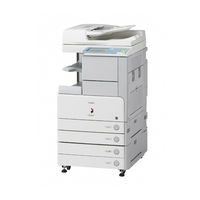
Canon 3235 Series Laser Printer Manuals
Manuals and User Guides for Canon 3235 Series Laser Printer. We have
1
Canon 3235 Series Laser Printer manual available for free PDF download: Service Manual
Canon 3235 Series Service Manual (746 pages)
Brand:
Canon
| Category:
Copier
| Size: 30.43 MB
Table of Contents
Table of Contents
7
Table of Contents
13
Chapter 1 Introduction
25
System Construction
29
System Configuration of Original Feeding Options
29
System Configuration of Pickup/Delivery Options
30
System Configuration of Print/Send Options
32
Functions of Print/Send Options
34
Product Specifications
35
Names of Parts
35
External View
35
Cross-Section
36
Using the Machine
37
Turning on the Power Switch
37
When Turning off the Main Power Switch
37
Control Panel
39
User Mode Items
40
Overview
40
Common Settings
40
Timer Settings
41
Adjustment/Cleaning
41
Report Settings
42
System Settings
42
Copy Settings
44
Communications Settings*2
45
Mail Box Settings
46
Address Book Settings*5
46
Maintenance by the User
47
Routine Cleaning
47
Inspection
50
Safety
51
Points to Note at Disassembly/Assembly
51
Safety of the Laser Light
51
CDRH Regulations
51
Handling the Laser Unit
51
Safety of Toner
52
Notes When Handling a Lithium Battery
53
Product Specifications
53
Methods/Functions
53
Function List
54
Printing Speed
54
Paper Type
56
Chapter 2 Installation
65
Table of Contents
67
Making Pre-Checks
69
Checking Installation Environment
69
Points to Note before Installation
70
Combination Table of Accessories
70
Checking the Contents
71
Unpacking and Installation
73
Unpacking and Removing Fixing Member
73
Installing the Filter
74
Installing Toner Container
75
Installing Drum Unit
76
Installing Other Parts
79
Fixing the Host Machine
81
Connecting the Cable
81
Points to Note When Turning off the Main Power
82
Stirring Toner
82
Cassette Setting
82
APVC Correction of Drum
82
Auto Gradation Correction
82
Screen Position Adjustment
83
Checking the Connection to the Network
85
Overview
85
Ping Operation Procedure
85
Checking Network with Remote Host Address
85
When Not Using Network Connection
85
Checking the Images/Operations
85
Checking the Image/Operation
85
Troubleshooting the Network
85
Check with Loopback Address
85
Check with Local Host Address
85
Installing the Card Reader
86
Installation Procedure
86
Installation Procedure in the Imageware Accounting Manager (Hereinafter Referred to Iwam) Environment
89
Installing the Original Holder
89
Checking Components
89
Installation Procedure
89
Checking Parts to Install
90
Turning off the Power of the Host Machine
91
Installation Procedure
91
Installing the Reader Heater
90
Installing the Cassette Heater
94
Checking Parts to Install
94
Turning off the Power of the Host Machine
94
Installation Procedure (Cassette Heater Unit)
94
Checking Parts to Install
98
Installation Procedure (Cassette Heater Attachment)
99
Installing the Deck Heater
103
Checking the Parts to Install
103
Turning off the Power of the Host Machine
103
Installation Procedure
103
Installing the Memory
106
Checking the Contents
106
Turning off the Power of the Host Machine
106
Installation Procedure
106
Installing the Memory (System Upgrade Memory)
106
Installing the Expansion Bus Kit
107
Checking the Contents
107
Turning off the Power of the Host Machine
107
Installation Procedure
107
Installing the Voice Guidance Kit
108
Notice at Installation
108
Checking the Contents
108
Turning off the Power of the Host Machine
108
Installation Procedure
108
Checking the Settings
111
Operation Check
111
Installing the Voice Operation Kit
111
Notice at Installation
111
Checking the Contents
111
Turning off the Power of the Host Machine
112
Installation Procedure
112
Checking the Settings
116
Operation Check
116
Installing the Wireless Network Interface Adapter
116
Notice at Installation
116
Checking the Contents
116
Turning off the Power of the Host Machine
116
Installation Procedure
117
Attaching the Label
118
Installing the Ipsec Board
118
Notice at Installation
118
Checking the Contents
118
Turning off the Power of the Host Machine
118
Installation Procedure
118
Functional Construction
125
Connecting the Main Pcbs
126
Basic Sequence of Operation at Power-On
127
Table of Contents
131
Construction
133
Construction and Mechanisms
133
Construction of the Electrical Circuitry
135
Hdd
137
Overview
138
Chapter 3 Basic Operation
138
Chapter 4 Main Controller
138
Start-Up Sequence
138
Overview
139
Shut-Down Sequence
139
Flow of Operation
139
Image Processing
140
Construction of the Image Processing Module
140
Reader Unit Input Image Processing
140
Compression/Extension/Editing Block
141
Printer Unit Output Image Processing
141
Flow of Image Data
142
Flow of Image Data According to Copy Functions
142
Flow of Image Data for the Box Function
142
Main Controller PCB
142
Flow of Image Data for the SEND Function
143
Flow of Image Data for the Fax Reception Function
144
Parts Replacement Procedure
145
Removing the Main Controller PCB
146
Sdram
146
Removing the SDRAM (for Image Processing)
146
Hdd
147
Removing the Sdram (for System Processing)
147
Removing the Hdd
147
Removing the Wireless Lan Pcb
147
Removing the Wireless LAN PCB
148
Ipsec PCB
148
Removing the Ipsec PCB
148
Wireless Lan Pcb
147
PCI Bus Expansion PCB
149
Removing the PCI Bus Expansion PCB
150
Voice Operation PCB
150
Removing the Voice Operation PCB
150
FAX Expansion PCB
151
Removing the FAX Expansion PCB
151
Table of Contents
155
Construction
157
Specifications/Controls/Functions
157
Major Components
158
Configuration of Control System
159
Reader Controller PCB
160
Basic Sequence
161
Basic Sequence at Power-On
161
Basic Sequence at Start Key on (Book Mode/1 Original)
161
Basic Sequence at Start Key on (ADF Mode/1 Original)
161
Various Control
162
Controlling the Scanner Drive System
162
Overview
162
Scanner Motor Control
162
CCD
164
Overview
164
Enlargement/Reduction
167
Chapter 5 Original Exposure System
167
Magnification in Sub Scanning Direction
167
Magnifications in Main Scanning Direction
167
Detecting the Size of Originals
168
Overview
168
Control Details
168
Detection Operation Overview
170
Dirt Sensor Control
171
Overview
171
White Board Dust Detection Control
173
Image Processing
174
Overview
174
CCD Drive
174
Gain Correction and Offset Correction of CCD Output
174
A/D Conversion of CCD Output
175
Shading Correction (Overview)
175
Shading Adjustment
175
Shading Correction
175
Parts Replacement Procedure
176
CCD Unit
176
Removing the CCD Unit
176
When Replacing the CCD Unit
177
CCD Cover Unit
177
Removing the CCD Cover Unit
177
Copyboard Glass
177
Removing the Copyboard Glass
177
When Replacing the Copyboard Glass
178
Removing the ADF Reading Glass
179
When Replacing the ADF Reading Glass
179
Reader Controller PCB
180
Points to Note before Replacing the Reader Controller PCB
180
Removing the Reader Controller PCB
180
After Replacing the Reader Controller PCB
180
LED Driver PCB
181
Removing the LED Driver PCB
181
Scanner Motor
181
Removing the Scanner Motor
181
Copyboard Cover Open/Close Sensor
181
Removing the Copyboard Cover Open/Closed Sensor (Front/Rear)
181
CCD HP Sensor
182
Removing the CCD Unit HP Sensor
182
Original Size Sensor
182
Removing the Original Size Sensor
182
Reader Heater (Option)
183
Removing the Reader Heater (Right)
183
Removing the Reader Heater (Left)
183
Table of Contents
187
Construction
189
Specifications/Controls/Functions
189
Main Configuration Parts
189
Chapter 6 Laser Exposure
190
Control System Configuration
190
Basic Sequence
191
Various Controls
192
Controlling the Laser Activation Timing
192
Laser ON/OFF Control
192
Main Scanning Synchronous Control
193
Controlling the Intensity of Laser Light
193
APC Control
193
Controlling the Laser Scanner Motor
194
Laser Scanner Motor Control
194
Controlling the Laser Shutter
195
Laser Shutter Control
195
Parts Replacement Procedure
196
Laser Scanner Unit
196
Before Removing the Laser Unit
196
Removing the Laser Unit
196
After Replacing the Laser Scanner Unit
196
Table of Contents
199
Construction
201
Specifications of the Image Formation System
201
Major Components of the Image Formation System
202
Image Formation Process
203
Image Formation Process (Outline)
203
Image Formation Process (Image Formation)
204
Basic Sequence
205
Chapter 7 Image Formation
205
Sequence of Operation (Copying)
205
Sequence of Operation (Last Rotation)
206
Image Stabilization Control
207
Overview
207
APVC Control
207
ATVC Control
207
PASCAL Control (Image Gradation)
208
Drum Unit
209
Outline of the Drum Unit
209
Configuration
209
Charging Mechanism
210
Controlling the Primary Charging Bias
210
Primary Charging Roller Cleaning Mechanism
210
Drum Cleaner Unit
210
Photosensitive Drum Cleaning
210
Developing Unit
211
Configuration
211
Controlling the Developing Bias
211
Toner Container
212
Configuration
212
Route of Toner Supply
213
Controlling the Drive of the Toner Cartridge
213
Toner Supply Control
214
Recovery Sequence
214
Toner Level Detection
214
Transfer Unit
215
Outline of the Transfer Unit
215
Outline
215
Controlling the Transfer Bias
215
Transfer Roller Bias Control
215
Cleaning
215
Transfer Roller Cleaning Mechanism
215
Separation Mechanism
215
Controlling the Static Eliminator Bias
215
Transfer Mechanism
216
Transfer Guide Bias
216
Transfer Guide Bias Control
216
Photosensitive Drum Cleaning
217
Outline
217
Collection of Waste Toner
217
Checking the Waste Toner Box
217
Drum Unit
218
Before Removing the Drum Unit
218
Removing the Drum Unit
218
After Replacing Drum Unit
219
Parts Replacement Procedure
218
Pre-Exposure Lamp
218
Before Removing the Pre-Exposure Lamp
218
Removing the Pre-Exposure Lamp
218
Hopper Assembly
219
Before Removing the Hopper Unit
219
Removing the Hopper Unit
219
Sub Hopper
220
Before Removing the Sub Hopper
220
Removing the Sub Hopper
220
Developing Assembly
221
Before Removing the Developing Assembly
221
Removing the Developing Assembly
221
After Replacing Developing Assembly/Developing Cylinder
222
Developing Cylinder
222
Before Removing the Developing Cylinder
222
Removing the Developing Cylinder
222
After Replacing Developing Assembly/Developing Cylinder
223
Transfer Charging Roller
224
Removing the Transfer Roller
224
Waste Toner Box
224
Removing the Waste Toner Container
224
Toner Level Sensor
225
Before Removing the Toner Level Sensor
225
Removing the Toner Feed Screw Motor
225
Before Removing the Toner Feed Screw Motor
225
Static Charge Eliminator
226
Removing the Static Eliminator
226
Table of Contents
229
Construction
233
Specifications, Controls, and Functions
233
Division into Blocks
234
Chapter 8 Pickup/Feeding System
235
Arrangement of Rollers
235
Diagram of Paper Paths (W/ 3 Way Unit-A1/ Copy Tray)
236
Diagram of Paper Paths (W/ Inbody Finisher/ Copy Tray)
237
Diagram of Paper Paths (W/ Finisher/Saddle Finisher)
238
Arrangement of Sensors
239
Route of Drive
240
Basic Sequence
242
Acceleration Intervals
242
Detecting Jams
246
Delay Jams
246
Delay Jam Outside the Cassette Pickup Assembly
246
Delay Jam in the Cassette Pickup Assembly
246
Stationary Jams
247
Common Stationary Jam
247
Stationary Jam at Power-On
247
Other Jams
247
Door Open Jam
247
Paper Size Mismatch JAM
248
Error Retry JAM
248
Cassette Pick-Up Unit
249
Overview
249
Basic Sequence
249
Identifying the Paper Size
250
Setting up the Universal Cassette
251
Paper Level Sensor
252
Manual Feed Pickup Unit
254
Overview
254
Basic Sequence of Operation
254
Identifying the Paper Size
255
Paper Retaining Mechanism
256
Registration Unit
257
Overview
257
Checking Horizontal Registration
257
Duplex Feeding Unit
258
Overview
258
Sequence of Image Formation
259
Flow of Paper
260
Parts Replacement Procedure
262
Sensor Mount
263
Cassette Pick-Up Motor 1
264
Cassette Pick-Up Motor 2
265
Cassette Paper Level Sensor (A/B)
266
Before Removing the Cassette Paper Level Sensor (A/B)
266
Removing the Cassette Paper Level Sensor (A/B)
266
Cassette Paper Sensor
266
Before Removing the Cassette Paper Sensor
266
Removing the Cassette Paper Sensor
266
Cassette Retry Paper Sensor
266
Before Removing the Cassette Retry Paper Sensor
266
Removing the Cassette Retry Paper Sensor
266
Slide Resistor
266
Removing the Slide Resistor
267
Cassette Pickup Solenoid
267
Before Removing the Cassette Pickup Solenoid
267
Removing the Cassette Pickup Solenoid
267
Manual Tray Assembly
267
Before Removing the Manual Feed Tray Unit
267
Removing the Manual Feed Tray Unit
267
When Replacing the Manual Feed Tray
268
Manual Feed Unit
268
Before Removing the Manual Feed Unit
268
Removing the Manual Feed Unit
268
Manual Pickup Roller
268
Before Removing the Manual Feed Pickup Roller
268
Removing the Manual Feed Pickup Roller
268
Manual Feeder Pad Up/Down Solenoid
269
Before Removing the Manual Feeder Pad Up/Down Solenoid
269
Removing the Manual Feeder Pad Up/Down Solenoid (Ir 3425/3235/3230)
269
Removing the Manual Feeder Pad Up/Down Solenoid (Ir 3225)
271
Manual Pick-Up Clutch
272
Before Removing the Manual Feed Pickup Clutch (Ir 3245/3235/3230)
272
Removing the Manual Feed Pickup Clutch (Ir 3245/3235/3230)
272
Before Removing the Manual Feed Pickup Clutch (Ir 3225)
272
Removing the Manual Feed Pickup Clutch (Ir 3225)
272
Manual Separation Pad
273
Before Removing the Manual Feed Separation Pad
273
Removing the Manual Feed Separation Pad
273
Registration Clutch
273
Before Removing the Registration Clutch
273
Removing the Registration Clutch
273
Way Unit
273
Before Removing the 3 Way Unit
273
Removing the 3 Way Unit
273
Feeding Roller
274
Vertical Path Roller
274
Duplex Feed Roller 2
275
Duplex Feed Sensor
276
Fixing/ Delivery Drive Assembly
277
Table of Contents
281
Construction
283
Major Components
283
Specifications, Control Mechanisms, and Functions
283
Basic Sequence
284
Power-On Sequence
284
Down Sequence
284
Various Control Mechanisms
285
Controlling the Speed of the Fixing Film
285
Controlling the Fixing Film Speed in Response to Low Temperature
285
Controlling the Fixing Film Speed
285
Controlling the Fixing Film Temperature
285
Controlling the Power Supply in Response to Low Temperature
285
Controlling the Feeding in Response to Low Temperature
285
Controlling the Power Supply at Start-Up
286
Copying Temperature Control
286
Changing the Fixing Film Control Temperature
286
Temperature Control in Response to Automatic Double-Sided Copy
286
Temperature Control in Response to Change of Paper Size
286
Fixing Film Cleaning
287
Detecting the Passage of Paper
287
Protective Functions
288
Detecting an Error
289
Parts Replacement Procedure
290
Fixing Unit
290
Before Removing the Fixing Unit
290
Removing the Fixing Unit
290
Pressure Roller
290
Before Removing the Pressure Roller
290
Removing the Pressure Roller
290
Cleaning Roller
291
Before Removing the Cleaning Roller
291
Removing the Cleaning Roller
291
Fixing Film
292
Before Removing the Fixing Film Unit
292
Removing the Fixing Film Unit
292
Internal Delivery Sensor
294
Before Removing the Internal Delivery Sensor
294
Removing the Internal Delivery Sensor
294
Fixing Film Sensor
295
Before Removing the Fixing Film Sensor
295
Removing the Fixing Film Sensor
295
Fixing Inlet Guide
296
Before Removing the Fixing Inlet Guide
296
Removing the Fixing Inlet Guide
296
Table of Contents
299
Control Panel
303
LCD Indication Processing
303
Adjusting the LCD Contrast
303
Adjusting Fax Sound Volume
303
Functions of the Control Panel CPU
304
Chapter 10 External and Controls
305
Counters
305
Timing of Increasing the Count
305
Fans
306
Speed Control
307
Operation Sequence
307
Power Supply System
308
Power Supply
308
Power Supply Route Inside the Printer
308
Power Supply Route in the Reader Unit
310
Timing of Supply to the Reader Unit
310
Connection to Options
311
Heater Operating Condition
311
Rated Output of the DC Power Supply PCB
311
Rated Output of the 24V Power Supply PCB
311
Rated Output of the 12V Power Supply PCB
312
Rated Output of the Option Power Supply PCB
312
Rated Output of the All-Night Power Supply PCB
312
Protection Function
312
Protective Functions
312
Backup Battery
312
Energy-Saving Function
313
Power Supply State
313
SNMP Settings
314
Parts Replacement Procedure
316
External Covers
316
Delivery Tray
316
Removing the Delivery Tray
316
Delivery Tray Right Cover
316
Before Removing the Delivery Tray Right Cover
316
Removing the Delivery Tray Right Cover
316
Delivery Tray Rear Cover
316
Before Removing the Delivery Tray Rear Cover
316
Removing the Delivery Tray Rear Cover
316
Support Cover
317
Before Removing the Support Cover
317
Removing the Support Cover
317
Support Cover (Right)
317
Before Removing the Support Right Cover
317
Removing the Support Right Cover
317
Right Cover (Lower Front)
318
Right Cover (Rear)
318
Removing the Rear Right Cover
318
Before Removing the Inside Right Cover
318
Removing the Inside Right Cover
318
Inside Bottom Cover
318
Before Removing the Inside Base Cover
318
Removing the Inside Base Cover
318
Removing the Front Cover Unit
319
Rear Cover (Upper)
319
Removing the Upper Rear Cover
319
Rear Cover (Lower)
319
Removing the Lower Rear Cover
319
Left Cover
319
Removing the Left Cover
319
Left Cover (Lower)
320
Removing the Lower Left Cover
320
Left Cover (Rear)
320
Before Removing the Rear Left Cover
320
Removing the Rear Left Cover
320
Delivery Cover
320
Removing the Delivery Cover
320
Toner Supply Cover
320
Removing the Toner Container Cover
320
Reader Left Cover
321
FAX Unit Cover
322
Removing the FAX Unit Cover
322
Control Panel Inside Frame
322
Before Removing the Control Panel Inside Frame
322
Removing the Control Panel Inside Frame
322
Control Panel Lower Cover
323
Removing the Control Panel Lower Cover
323
Main Drive Assembly
323
Before Removing the Main Drive Unit
323
Removing the Main Drive Unit (Ir 3245/3235/3230)
323
Removing the Main Drive Unit (Ir 3225)
324
Power Supply Unit
326
Before Removing the 12V Power Supply PCB
326
Removing the 12V Power Supply PCB
326
Before Removing the 24V Power Supply PCB
327
Control Panel LCD Unit
328
Before Removing the Control Panel LCD
328
Removing the Control Panel LCD
329
DC Controller PCB
329
Removing the DC Controller PCB
329
When Replacing DC Controller PCB
329
Control Panel Inverter PCB
330
Before Removing the Control Panel Inverter PCB
330
Removing the Control Panel Inverter PCB
330
Control Panel Key Switch PCB
330
Before Removing the Control Panel KEY PCB
330
Removing the Control Panel KEY PCB
330
Control Panel CPU PCB
330
Before Removing the Control Panel CPU PCB
330
Removing the Control Panel CPU PCB
331
Removing the Fax Unit
331
Control Panel Usb Pcb
331
Before Removing the Control Panel Usb Pcb
331
AC Driver PCB
332
Before Removing the AC Driver PCB
332
Removing the AC Driver PCB
332
All Night Power Supply PCB
332
Before Removing the All-Night Power Supply PCB
332
Removing the All-Night Power Supply PCB
332
Option Power Supply PCB
333
Before Removing the Option Power Supply PCB
333
Removing the Option Power Supply PCB
333
Relay PCB
333
Before Removing the Relay PCB
333
Removing the Relay PCB
333
High-Voltage PCB
333
Before Removing the High-Voltage Power Supply PCB
333
Removing the High-Voltage Power Supply PCB
334
Before Removing the Power Supply Cooling Fan
334
Removing the Power Supply Cooling Fan
334
Exhaust Fan
335
Motor of Main Drive Assembly
336
Removing the Main Motor (Ir 3245/3235/3230)
336
Before Removing the Main Motor (Ir 3225)
337
Removing the Main Motor (Ir 3225)
337
Fixing Driver Motor
337
Removing the Fixing Driver Motor
337
Right Door/Right Cover
338
Releasing the Right Cover
338
Removing the Right Cover
339
Circuit Breaker
341
Before Removing the Circuit Breaker
341
Removing the Circuit Breaker
341
Meap
345
Checking the Operating Environment
347
Setting up the Network
350
Login to SMS
352
Setting the Method to Login to SMS
354
Checking Application List
358
Chapter 11 Starting and Stopping a MEAP Application
358
Checking the Platform Information
359
MEAP Specifications
360
Mfid
362
Checking the System Information of a MEAP Application with SMS
364
Printing the System Information of a MEAP Application
365
Reference (Application System Information)
366
Installing an Application
367
MEAP Enterprise Service Manager
369
Adding a License File
370
Disabling a License File (Suspending a License)
372
Downloading/Removing an Invalidated License File
373
Reusable License
375
License for Forwarding
375
Uninstalling an Application
378
Login Service
379
Changing Login Services
384
Initializing the Password
385
Creating a Backup for MEAP Application Area, Formatting the Hard Disk, Restoring the MEAP Application Area with the Backup, Using the SST (Service Support Tool)
386
Replacing the Hard Disk Drive
386
MEAP Safe Mode
387
Setting HTTP Port for MEAP Application (Level 2)
388
USB Keyboard Support
390
USB Memory Related Functions(Supported Outside of Japan and Europe)
391
Reference Material
393
Option for Exclusive Individual Measure
394
Chapter 12 E-Maintenance/Imageware Remote
397
Meap
347
Overview
347
E-Maintenance/Imageware Remote
397
Overview
401
Settings Procedures
401
Troubleshooting Guide
404
Service Cautions
407
Chapter 13 Maintenance and Inspection
409
Table of Contents
411
Durables and Consumables
413
Adf
413
Reader
413
Printer Unit
414
Periodically Replaced Parts
413
Overview
413
Scheduled Servicing Basic Procedure
415
Scheduled Servicing for Reader Unit
415
Scheduled Servicing for the Printer Unit
416
Cleaning
419
Cleaning Fixing Entrance Guide
419
Cleaning the Mirror Inside CCD Unit
420
Cleaning Film Bias Static Eliminator
423
After Replacing Developing Assembly/Developing Cylinder
427
Chapter 14 Standards and Adjustments
429
Image Adjustments
429
Standards for Image Position
429
Adjusting the Image Position
429
Left End Margin Adjustment (each Pickup Position Basis)
430
Scanning System
432
When Replacing the Adf Scanning Glass
432
Electrical Components
434
After Replacing the Main Controller
434
After Replacing the Hard Disk
434
When Replacing DC Controller PCB
435
Image Formation System
434
Laser Exposure System
434
Pickup/Feeding System
435
When Replacing the Cassette
435
When Replacing the Duplex Unit
435
Table of Contents
439
Chapter 15 Correcting Faulty Images
441
Checking Consumables
441
Checking Periodical Service Item
441
Checking each Unit/Each Function System
442
Checking Paper
441
Checking Paper Set
441
Installation Procedure
441
Making Initial Checks
441
Clutch/Solenoid
443
Outline of Electrical Components
443
Clutches and Solenoids (Printer)
443
Motors (Reader)
444
Motors (Printer)
444
Fans (Reader)
445
Fans (Printer)
445
Sensor
446
Sensors (Reader)
446
Sensors (Printer)
446
Switches (Reader)
448
Switches (Printer)
448
Lamps, Heaters, and Others (Reader)
448
Lamps, Heaters, and Others (Printer)
449
Pcbs
450
Pcbs (Reader)
450
Pcbs (Printer)
450
Connectors
452
Connectors (2/6)
454
Connectors (1/6)
456
Connectors (2/6)
458
Connectors (5/6)
460
Connectors (6/6)
462
Variable Resistors (VR), Light-Emitting Diodes (LED), and Check Pins by PCB
464
Variable Resistors (Vr), Light-Emitting Diodes, and Check Pins by Pcb
464
Points to Note about the Leakage Breaker
464
Table of Contents
467
E000 to E197 (DC Controller)
469
Error Code Details
469
E202 to E248, E280 (Reader)
471
E261 to E315 (DC Controller, Main Controller)
471
E400, E413, E490 (Adf)
472
E500 to E5F9 (Finisher)
473
E602 (Error in Hdd/Encryption Board)
475
Detail in E602
476
E604 to E748 (Main Controller, DC Controller)
478
E804 to E805 (DC Controller Control Fan)
481
Error Code (Send)
482
Self-Diagnostic Display
482
List of Error Codes Without Messages
483
Jam Codes (Printer Unit)
489
Jam Code (Adf)
489
Jam Codes (Finisher)
490
Alarm Code
490
Table of Contents
495
Outline
499
Construction of Service Mode
499
Starting Service Mode and Making Selections
500
Ending Service Mode
500
Back-Up
500
Initial Screen
501
Th Item Screen
502
Display (Status Display Mode)
503
Copier > Display > Acc-Sts
517
Copier > Display > Analog
520
Copier > Display > Cst-Sts
521
Copier > Display > Jam
522
Copier > Display > Err
522
Copier > Display > Hv-Sts
523
Copier > Display > CCD
524
Copier > Display > Sensor
526
Copier > Display > Alarm
526
Copier > Display > Envrnt
526
Feeder
527
Feeder > Display
527
I/O (I/O Display Mode)
527
DC-Con>
528
R-Con>
530
Sorter>
531
Adjust (Adjustment Mode)
536
Copier > Adjust > Adj-Xy
536
Copier > Adjust > Ae
536
Mn-Cont>
536
Copier > Adjust > CCD
538
Copier > Adjust > Laser
553
Copier > Adjust > Develop
555
Copier > Adjust > Blank
556
Copier > Adjust > Dens
556
Copier > Adjust > Hv-Pri
557
Copier > Adjust > Pascal
557
Copier > Adjust > Hv-Tr
558
Copier > Adjust > Feed-Adj
567
Copier > Adjust > Cst-Adj
570
Copier > Adjust > Fixing
571
Copier > Adjust > Misc
572
Feeder
575
Feeder > Adjust
575
Sorter
576
Sorter > Adjust
576
Function (Operation/Inspection Mode)
577
Copier > Function > Install
577
Points to Note When Operate the Service Mode (Function)
577
Copier > Function > CCD
579
Copier > Function > Cst
581
Copier > Function > Dens
581
Copier > Function > Dpc
581
Copier > Function > Fixing
582
Copier > Function > Panel
583
Copier > Function > Part-Chk
584
Copier > Function > Clear
586
Copier > Function > Misc-P
591
Copier > Function > Misc-R
591
Copier > Function > System
594
Feeder
595
Feeder > Function
595
Option (Machine Settings Mode)
599
Copier > Option > Body (2/15)
602
Copier > Option > Body (3/15)
605
Copier > Option > Body (4/15)
607
Copier > Option > Body (5/15)
609
Copier > Option > Body (6/15)
611
Copier > Option > Body (7/15)
612
Copier > Option > Body (8/15)
614
Copier > Option > Body (9/15)
616
Copier > Option > Body (10/15)
618
Copier > Option > Body (11/15)
620
Copier > Option > Body (12/15)
622
Copier > Option > Body (13/15)
624
Copier > Option > Body (14/15)
627
Copier > Option > Body (15/15)
630
Copier > Option > User (1/7)
631
Copier > Option > User (2/7)
639
Copier > Option > User (3/7)
642
Copier > Option > User (4/7)
645
Copier > Option > User (5/7)
648
Copier > Option > User (6/7)
651
Copier > Option > User (7/7)
653
Copier > Option > Cst
655
Copier > Option > Acc
658
Copier > Option > Int-Face (1/2)
660
Copier > Option > Int-Face (2/2)
661
Copier > Option > Combo
662
Copier > Option > Lcns-Tr
664
Feeder
674
Feeder > Option
674
Sorter
675
Sorter > Option
675
Board > Option
675
Test (Test Print Mode)
676
Copier > Test > Pg
676
Copier > Test > Network
677
Copier > Test > Net-Cap
678
Counter (Counter Mode)
680
Copier > Counter > Total
680
Copier > Counter > Pick-Up
681
Copier > Counter > Feeder
682
Copier > Counter > Jam
682
Copier > Counter > Misc
683
Copier > Counter > Drbl-1
684
Copier > Counter > Drbl-2
686
Table of Contents
693
Outline of Upgrading the Machine
695
Outline of the Service Support Tool
696
Points to Note at Time of Downloading
698
Making Preparations
699
Installing the System Software (System CD -> Sst)
699
Installing the System Software (Sst -> Usb)
701
Making Connections (Sst in Use)
703
Making Connections (Usb Device in Use)
705
Formatting the Hdd
707
Formatting Selected Partitions
707
Formatting Procedure
708
Downloading System Software
710
Downloading the System Software (All)
710
Downloading Procedure (Assist Mode)
712
Downloading Procedure (Normal Mode)
716
Downloading Procedure
719
Downloading the System Software (Single)
719
Downloading Dcon and Rcon
722
Downloading G3 FAX
723
Uploading and Downloading Backup Data
724
Uploading Procedure
725
Downloading Procedure
727
Version Upgrade Using USB
729
Overview of Menus and Functions
729
Points to Note
730
Downloading/Writing the System Software (Auto)
731
Downloading the System Software (Confirmation Execution When Version Is Downed the same Version)
732
Downloading the System Software (All Overwriting)
733
Formatting the HDD
735
Other Functions
736
Chapter 19 Service Tools
741
Service Tools
741
Oils and Solvents
743
Service Tools
743
Special Tools
743
Advertisement
Advertisement
Related Products
Canon imageRUNNER 3300
Canon image RUNNER 3035
Canon image RUNNER 3045
Canon 3230
Canon 3225
Canon image runner 3025
Canon image runner 3030
Canon 3100
Canon 3238B001 - XH A1S Camcorder
Canon 3235B001
Canon Categories
Printer
Digital Camera
All in One Printer
Camcorder
Scanner
More Canon Manuals
Login
Sign In
OR
Sign in with Facebook
Sign in with Google
Upload manual
Upload from disk
Upload from URL