Sign In
Upload
Manuals
Brands
Canon Manuals
Printer
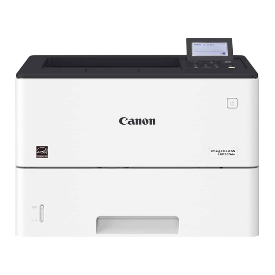
imageCLASS LBP325dn
Canon imageCLASS LBP325dn Manuals
Manuals and User Guides for Canon imageCLASS LBP325dn. We have
2
Canon imageCLASS LBP325dn manuals available for free PDF download: Service Manual, Getting Started
Canon imageCLASS LBP325dn Service Manual (252 pages)
Brand:
Canon
| Category:
Printer
| Size: 20.3 MB
Table of Contents
Table of Contents
5
Safety Precautions
11
Laser
12
Laser Safety
12
How to Handle the Laser Scanner Unit
12
Power Supply / Lithium Battery
13
Power Supply
13
Notes When Handling a Lithium Battery
13
Toner Safety
13
About Toner
13
Handling Adhered Toner
13
Notes on Works
14
Points to Note before Servicing
14
Points to Note at Cleaning
14
Notes on Assembly/Disassembly
14
Product Overview
15
Product Lineup
16
Host Machine
16
Options
16
Features
17
Specifications
18
Product Specifications
18
Paper Type
19
Paper Size
19
Parts Name
21
Front Side of the Machine
21
Rear Side of the Host Machine
22
Inside of the Host Machine
23
Cross Section View
23
Control Panel
24
Technical Explanation (Device)
25
Basic Configuration
26
Functional Configuration
26
Controller System
27
Configuration/Function
27
Main Controller PCB
28
DC Controller PCB
29
Motor Control
29
Fan Control
30
Door Open Detection
31
Power Supply
31
Protection Function
32
Quick Startup
33
Energy Saving Function
34
Laser Exposure System
35
Overview
35
Failure Detection
35
Image Formation System
37
Image Formation Process
37
Cartridge
40
Fixing System
43
Overview/Configuration
43
Fixing Temperature Control
43
Protective Functions
44
Pickup Feed System
46
Overview
46
Parts Configuration
47
Drive Configuration
48
Layout of Sensors
49
Lifter Control
49
Cassette Detection
50
Cassette Pickup Control
51
Cassette Double Feed Prevention Mechanism
51
Paper Detection
51
Multi-Purpose Tray Pickup Control
51
Skew Correction
52
Paper Width Detection
53
Paper Length Detection
54
Feed Speed Control
54
Delivery Tray Full Detection
55
Jam Detection
55
Technical Explanation (System)
58
Version Upgrade
59
Overview
59
Version Upgrade Using UST
60
Update Using Updater
60
Version Upgrade Using a USB Flash Drive
88
Backup/Restoration
89
Backup/Restoration Using the DCM Function
89
Backup/Restoration Using a Function Other than the DCM Function
98
Monitoring Function (E-Maintenance/Imageware Remote)
105
Monitoring Function (E-Maintenance/ Imageware Remote)
105
Overview of System
105
Cautions When Using E-RDS
106
Setting Procedure
106
Maintenance
108
Error Message List
109
MEAP Application Management
111
About MEAP
111
About SMS
111
Setting Procedure
116
Maintenance
124
Periodical Service
127
Periodically Replaced Parts
128
Consumable Parts
129
Periodical Service
130
Parts Replacement and Cleaning
131
Parts List
132
Major Units
132
Electrical Components List
132
Removing from the Connection Equipment
135
Disengaging the Paper Feeder
135
External Cover System
137
Removing the Rear Cover Unit
137
Removing the Cartridge
137
Removing the Right Cover Unit
139
Removing the Left Cover
143
Removing the Upper Cover Unit
146
Removing the Cartridge Cover
147
Controller System
150
Removing the Controller Cover
150
Removing the Main Controller PCB
150
Removing the Controller Box
154
Removing the DC Controller PCB
156
Removing the Fixing Power Supply PCB
156
Removing the Low Voltage Power Supply Unit
159
Removing the High Voltage Power Supply PCB
159
Removing the Control Panel Unit
160
Removing the Control Panel Unit Key PCB
161
Removing the Main Fan
162
Removing the Sub Fan
163
Laser Exposure System
165
Removing the Laser Scanner Unit
165
Image Formation System
167
Removing the Transfer Roller Unit
167
Pickup Feed Delivery System
169
Removing the Registration Unit
169
Removing the Main Drive Unit
172
Removing the Cassette Pickup Unit
175
Removing the Cassette Separation Roller Unit
177
Removing the Multi-Purpose Tray Pickup Roller
178
Removing the Multi-Purpose Tray Separation Pad
179
Fixing System
182
Removing the Fixing Assembly
182
Removing the Main Motor
183
Adjustment
187
Actions at Parts Replacement
188
Before Replacing the Main Controller PCB
188
After Replacing the Main Controller PCB
188
Troubleshooting
189
Test Print
190
Overview
190
How to View the Test Print D1
194
Device Log List
195
Cartridge Log Print
196
Troubleshooting
198
Remedy for Image Failure
198
Image Failures Occur at Regular Intervals
198
Checking the Amount of Fixing Nip
198
Obtaining Debug Log
200
Function Overview
200
Debug Log
200
Conditions for Collecting Logs
200
Debug Log Collection Procedure
201
Error/Jam/Alarm
204
Overview
205
Error Code
207
E000-0000-- Fixing Temperature Rising Error
207
E001-0000--: Abnormally High Fixing Temperature 1
207
E004-0000-- Fixing Drive Assembly Circuit Error
207
E004-0005-- Fixing Area Error
207
E014-0000-- Main Motor Error
207
E014-0001-- Main Motor Error
207
E015-0001-- Cassette 1 Lift-Up Error
207
E015-0002-- Cassette 2 (Option Cassette 1) Lift-Up Error
207
E015-0003-- Cassette 3 (Option Cassette 2) Lift-Up Error
208
E015-0004-- Cassette 4 (Option Cassette 3) Lift-Up Error
208
E066-0000-- Environment Sensor Error
208
E06F-0068-- EEPROM Access Error
208
E100-0000-- Laser Scanner Error
208
E110-0000-- Scanner Motor Error
208
E110-0001-- Scanner Motor Error
208
E196-0000-- Firmware Error (the Host Machine or the Option Cassette)
208
E196-0002-- DC Controller Internal Error
208
E245-1011-- Host Machine FRAM Write Error
208
E245-1012-- Host Machine FRAM Write Error
209
E245-1013-- Host Machine FRAM Write Error
209
E245-1021-- Host Machine FRAM Write Error
209
E245-1022-- Host Machine FRAM Write Error
209
E245-1023-- Host Machine FRAM Write Error
209
E245-2012-- FLASH Write Error
209
E245-2022-- FLASH Write Error
209
E246-0001-- System Error
209
E246-0002-- System Error
209
E246-0003-- System Error
209
E247-0003-- System Error
210
E247-0004-- System Error
210
E350-1001-- System Error
210
E350-1002-- System Error
210
E350-1003-- System Error
210
E350-3000-- System Error
210
E354-0001-- System Error
210
E354-0002-- System Error
210
E355-0001-- System Error
210
E355-0003-- System Error
210
E602-0006-- Firmware Error
211
E602-0007-- Firmware Error
211
E602-0008-- the Memory Area in the Main Controller Is Depleted
211
E602-0009-- MEAP Cannot be Started
211
E602-1102-- File System Could Not be Initialized Normally. (MEAP-Related)
211
E602-1112-- Device Access Error (MEAP-Related)
211
E602-1113-- Device Access Error (MEAP-Related)
211
E602-1302-- File System Could Not be Initialized Normally
211
E602-1312-- Device Access Error
211
E602-1313-- Device Access Error
211
E602-1602-- File System Could Not be Initialized Normally. (CDS-Related)
212
E602-1612-- Device Access Error (CDS-Related)
212
E602-1613-- Device Access Error (CDS-Related)
212
E604-0000-- Insufficient Memory Capacity
212
E604-0001-- Memory Error
212
E616-0001-- MEAP Application Is Lost
212
E616-0002-- System Error
212
E730-100A-- System Error
212
E730-C000-- an Error, such as Failure in Memory Retrieval at Initialization, Occurred
212
E730-C001-- an Error Occurred When Accessing the Controller
212
E733-0001-- Printer Communication Error
213
E733-0004-- Printer Communication Error
213
E733-0006-- Printer Communication Error
213
E740-0002-- an Invalid MAC Address Has Been Detected
213
E740-0004-- Network Chip Error Detection
213
E744-0800-- Model Code Mismatch
213
E744-0900-- Detection of Invalid Bootable
213
E744-1000-- Firmware Error
213
E744-1100-- System Error
213
E748-2012-- FLASH Rewrite Error
213
E760-0000-- Firmware Error
214
E805-0001-- Main Fan Failure
214
E805-0002-- Sub Fan Failure
214
E808-0001-- Low-Voltage Power Supply Failure
214
E840-0000-- Fixing Disengagement Error
214
Jam Code
215
Jam Occurring Area and Detection Sensor for Jam Message on the Control Panel When Jam Code Cannot be Confirmed
217
Alarm Code
218
10-0100: Cartridge Replacement Completion Alarm
218
10-0404: Cartridge Empty Alarm
218
Alarm Codes Generated by UGW
218
Service Mode
219
Overview
220
Entering Service Mode
220
Remote UI Service Mode
220
Service Report
221
Service Mode
224
Adjust Gr
224
Option Gr
225
Crgmng Gr
227
Function Gr
229
Log Gr
234
Panel Lock Gr
235
F/W Update Gr
235
Network Gr
236
Sp.admin.mode
242
Installation
243
Installation of the Host Machine
244
Operation When Using Uniflow Online
244
Appendices
245
Service Tools
246
Special Tools
246
Solvents and Oil List
246
General Circuit Diagram
247
General Circuit Diagram (1/2)
247
General Circuit Diagram (2/2)
248
List of Items Which Can be Imported
249
Service Mode Items Which Can be Imported
249
Backup Data List
251
Backup Data
251
Soft Counter Specifications
252
Advertisement
Canon imageCLASS LBP325dn Getting Started (37 pages)
Brand:
Canon
| Category:
Printer
| Size: 12.89 MB
Table of Contents
Quick Setup
2
Installation of the Machine
3
Items Included with the Machine
3
Installing the Machine
3
Configuring the Machine
8
Installing the Software
9
Configuration Rapide
10
Configuration de L'appareil
10
Connexion Par USB
11
Installation du Logiciel
11
Configuración del Equipo
12
Instalar el Software
13
Navigating the Menu
16
Setting Confirmation
16
Loading Paper
18
Replacing the Toner Cartridge
19
Important Safety Instructions
20
Chargement du Papier
24
En Cas de Problème
25
Consignes de Sécurité Importantes
26
Funcionamiento Rápido
28
Cargar Papel
30
Instrucciones de Seguridad Importantes
32
Advertisement
Related Products
Canon LBP-3200
Canon LASER SHOT LBP3210
Canon LBP-3260
Canon LBP3200 Series
Canon imageClass LBP320 Series
Canon LBP3250 Series
Canon Satera LBP-3920
Canon Satera LBP-3700
Canon Satera LBP3410
CANON LBP 3370
Canon Categories
Printer
Digital Camera
All in One Printer
Camcorder
Scanner
More Canon Manuals
Login
Sign In
OR
Sign in with Facebook
Sign in with Google
Upload manual
Upload from disk
Upload from URL