Sign In
Upload
Manuals
Brands
Canon Manuals
All in One Printer
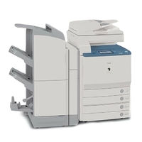
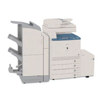
imageRUNNER C4080 SERIES
Canon imageRUNNER C4080 SERIES Manuals
Manuals and User Guides for Canon imageRUNNER C4080 SERIES. We have
4
Canon imageRUNNER C4080 SERIES manuals available for free PDF download: Service Manual, Brochure, Specifications
Canon imageRUNNER C4080 SERIES Service Manual (851 pages)
Brand:
Canon
| Category:
All in One Printer
| Size: 39.99 MB
Table of Contents
Table of Contents
5
Table of Contents
20
Chapter 1 Introduc Tion
24
System Construction
24
System Configuration with Printing/Transmission Accessories [USA]
25
Functions of Printing/Transmission Accessories
26
Product Specifications
28
Cross Section
30
Using the Machine
32
Points to Note about Turing off the Main Power Switch
34
Control Panel
36
Timer Settings
39
Report Settings
40
System Settings
41
Copy Settings
44
Mail Box Settings
46
User Maintenance
47
Inspection
49
Safety
50
Laser Safety
51
Safety of Toner
52
Notes When Handling a Lithium Battery
53
Product Specifications
54
Function List
55
Print Size
61
Others
62
Reader Unit Specifications
63
Chapter 2 Installation
67
Making Pre-Checks
67
Spatial Requirements
69
Order of Installing Accessories
71
Checking the Contents
72
Unpacking and Installation
74
Mounting the Transfer Cleaning Unit
79
Fitting the Toner Container in Place
81
Fitting the Drum Unit in Place
82
Fitting the Secondary Transfer Outside Roller Unit in Place
84
Cassette Setup
86
Other Work
87
Dealing with Power Code Mount
88
Connecting the Power Cord
90
Adjustment of the Margin Along Leading Edge of Image
93
Checking the Connection to the Network
94
Installing the Copy Tray
95
Installation Procedure
96
Installing the Card Reader
97
Installation Procedure in the Imageware Accounting Manager (Henceforth Iwam) Environment
99
Installation Procedures
100
Installation Procedures
101
Checking after the Installation
102
Installing the Voice Guidance Kit
103
Turning off the Host Machine
104
Construction
112
Basic Sequence
113
Basic Sequence of Operations
115
Chapter 5 Main Controller
120
Construction of the Electrical Circuitry
120
DC Controller PCB 1 (IMG)
121
DC Controller PCB 2 (MAISY)
124
Basic Sequence
126
Construction
131
Chapter 3 Bas IC Operat Ion
133
Chapter 4 Bas IC Operat Ions (as a Printer)
133
Construction of the Electrical Circuitry
133
SRAM Circuit Board
134
Start-Up Sequence
135
Actions When HDD Error
139
Image Processing
143
Reader Input Image Processing
144
Printer Output Image Processing
145
Compression, Decompression, and Edit Processing Blocks
146
Flow of Image Data
147
Flow of Image Data for Box Functions
148
Flow of Image Data for SEND Functions
149
Flow of Image Data for Fax Transmission Functions
150
Flow of Image Data for Fax Reception Functions
151
Flow of Image Data for PDL Functions
152
Parts Replacement Procedure
153
Main Controller PCB (Sub R-A)
157
Main Controller PCB (Sub PDRM-A)
158
Main Controller PCB (Sub LAN-A)
159
Main Controller PCB (Sub RB-A)
160
Sram Pcb
161
Image Memory (SDRAM)
162
Removing the Hdd
163
Controller Fan
164
Chapter 6 Original Exposure System
166
Construction
168
Specifications, Control Mechanisms, and Functions
168
Major Components
169
Construction of the Control System
171
Reader Controller PCB
172
Basic Sequence
173
Basic Sequence of Operation at Power-On
173
Basic Sequence of Operation in Response to a Press on the Start Key
174
Various Control Mechanisms
176
Controlling the Scanner Drive System
176
Overview
176
Controlling the Scanner Motor
177
Enlargement/Reduction
178
Changing the Magnification in Main Scanning Direction
178
Changing the Magnification in Sub Scanning Direction
178
Controlling the Scanning Lamp
178
Overview
178
Scanning Lamp
179
Turning on and off the Scanning Lamp
179
Detecting the Size of Originals
179
Identifying the Size of Originals
179
Points of Measurement Used for Original Size Identification
180
Overview of Operation
182
Dirt Sensor Control
184
Stream Reading Dust Detection Control
184
White Plate Dust Detection Control
186
Image Processing
188
Overview
188
CCD Drive
189
CCD Gain Correction, Offset Correction
189
CCD Output A/D Conversion
189
Outline of Shading Correction
189
Shading Adjustment
190
Shading Correction
190
Parts Replacement Procedure
191
Copyboard Glass
191
Exposure Lamp
191
Reader Controller PCB
192
Interface PCB
194
Inverter PCB
195
CCD Unit
196
Scanner Motor
197
ADF Open/Close Sensor
198
Scanner HP Sensor
199
Cooling Fan
200
Original Sensor
200
Scanner Drive Cable
201
Shading Correction
211
Chapter 8 Laser Exposure
213
Construction
214
Specifications, Control Mechanisms, and Functions
214
Major Components
215
Construction of the Control System
216
Basic Sequence
217
Basic Sequence of Operation
217
Various Control
218
Controlling the Laser Activation Timing
218
ON/OFF Control
218
Controlling Synchronization in Main Scanning Direction
222
Controlling Synchronization in Sub Scanning Direction
223
Controlling the Intensity of Laser Light
223
APC Control
223
PWM Control
224
Controlling the Laser Scanner Motor
225
Laser Scanner Motor Control
225
Laser Scanner Motor Speed Change Control
226
Controlling the Laser Shutter
227
Laser Shutter Control
227
Correcting Image Displacement
228
Outline
228
Timing of Color Displacement Detection/Correction
229
Detecting/Correcting Color Displacement in Sub Scanning Direction
230
Detecting/Correcting the Angle in Main Scanning Direction
231
Detecting/Correcting Color Displacement in Main Scanning Direction
233
Detecting/Correcting Changes in the Reproduction Ratio in Main Scanning Direction
234
Parts Replacement Procedure
236
Laser Unit
236
Chapter 9 Image Formation
240
Construction
242
Specifications, Control Mechanisms, and Functions
242
Major Components of the Image Formation System
245
Charging Specifications
246
Image Formation Process
248
Image Formation Process (General)
248
Image Formation Process (Image Formation)
249
Image Formation Process (Transfer)
250
Basic Sequence
251
At Power-On (1)
251
At Power-On (2)
252
During Copying/Printing Operations (Normal Speed)
253
Making Copies/Prints (Half Speed)
254
After Replacing the Drum Unit (D-UNIT)
255
Printing Originals Containing a Color Page
256
Driving and Controlling the Image Formation System
257
Driving and Controlling the Image Formation System and the High-Voltage System
257
Image Stabilization Control
259
Outline of Image Quality Control
259
Automated Image Stabilization Control
259
ATR Control
260
ATR Control
263
Discharge Current Level Control
264
ATVC Control (Transfer Bias Level Correction)
264
PASCAL Control (Image Gradation)
265
SALT-Dmax Control (Development Characteristics Correction)
266
SALT-Dhalf Control (Development Characteristics Correction)
267
Auto Gradation Control
268
Drum Unit
270
Outline of the Drum Unit
270
Drum Receptacle Presence / Absence Detection
270
Drum Unit (D-UNIT) Drive Control
271
Developing Assembly
272
Construction of the Developing Assembly
272
Controlling the Developing Bias
273
Auxiliary Brush
275
Construction of the Auxiliary Brush
275
Controlling the Auxiliary Bias
276
Charging Mechanism
280
Construction of the Charging Mechanism
280
Controlling the Charging Bias
281
Toner Container
283
Outline of the Toner Container
283
Toner Receptacle Presence / Absence Detection
283
Controlling the Toner Container Drive
284
Checking the Level of Toner
285
Controlling the Supply of Toner
286
Transfer Unit
287
Outline of the Transfer Unit
287
Transfer Unit Drive Control
288
Controlling the Transfer Bias
289
Transfer Bias Control
289
Cleaning
291
Intermediate Transfer Belt (ITB)
291
Secondary External Roller
292
Waste Toner Collection Mechanism
292
Separation Mechanism
293
Separation
293
Parts Replacement Procedure
295
Drum ITB Motor
295
Drum Drive Unit
296
Drum ITB Motor
296
Drum Drive Unit
297
Drive Roller
298
Developing Motor (Bk/Y/M/C)
299
Secondary Transfer Unit
300
Intermediate Transfer Unit
301
Transfer Cleaning Unit
303
Intermediate Transfer Belt
303
Transfer Belt
304
Intermediate Transfer Belt Tension Roller
307
Primary Transfer Roller
307
Secondary Transfer External Roller
308
Secondary Transfer Internal Roller
310
Toner Container Drive Unit
311
Waste Toner Detection PCB
312
Feedscrew Rotation Sensor
314
Tone Container Motor
316
Waste Toner Feedscrew Case
318
Pattern Reader Unit
320
Auto Registration Sensor PCB
321
SALT Sensor
322
Chapter 10 Pickup/Feeding System
325
Construction
328
Specifications, Control Mechanisms, and Functions
328
Arrangement of He Units
329
Arrangement of Rollers
330
Diagram of the Paper Paths
331
Arrangement of Sensors
332
Arrangement of the Clutches and Solenoids
333
Route of Dive
334
Basic Sequence
335
Basic Sequence of Operations at Power-On
335
Basic Sequence of Operations in Response to a Press on the Start Key
335
Detecting Jams
336
Delay Jams
336
Delay Jam in the Cassette Pickup Assembly
336
Delay Jam Outside the Cassette Pickup Assembly
336
Stationary Jams
337
Stationary Jams at Power-On
338
Cassette
339
Identifying the Paper Size
339
Detecting the Level of Paper
341
Cassette Pick-Up Unit
343
Outline
343
Basci Sequence of Operations
344
Manual Feed Pickup Unit
345
Outline
345
Basic Sequence of Operations
346
Identifying the Size of Paper
346
Detecting the Presence/Absence of Paper
347
Detecting the Last Paper
348
Registration Unit
349
Outline
349
Duplex Feeding Unit
351
Outline
351
Controling Horizontal Registration
352
Face-Down Delivery, A4, 5 Sheets in Circulation
353
Face-Down Delivery, A3, 3 Sheets in Cirucilation
356
Delivery
359
Movement in the Direction of Face-Down Delivery
360
Movement in the Direction of Face-Up Delivery
361
Movement for Centertray Delivery
362
Moement for Copy Tray Dievyer
362
Parts Replacement Procedure
363
Cassette Pickup Unit
363
Cassette Size Detection Unit
363
Pre-Registration Roller
364
Registration Upper Roller
365
Re-Pickup Roller
366
Pickup Roller
367
Feed Roller
368
Separation Roller
368
Cassette Pickup Motor
369
Cassette Retry Paper Sensor
370
Cassette Paper Sensor
372
Cassette Paper Level Sensor (A/B)
374
Slide Resistor
377
Cassette Pickup Solenoid
378
Manual Feed Tray Unit
379
Manual Feed Unit
379
Manual Feed Roller
380
Manual Feed Separation Roller
381
Separation Roller
382
Manual Feed Last Paper Sensor
383
Manual Feed Sensor
384
Transparency Sensor (Front/Rear)
385
Manual Feed Pickup Solenoid
385
Registration Motor
386
Pre-Registration Motor
387
Horizontal Registration Motor
387
Registration Sensor
389
Fixing/Feeder Unit
389
Pickup Vertical Path Roller
390
Inside Delivery Roller
392
Fixing/Feeder Unit Open/Closed Sensor
393
Fixing Arching Sensor
396
Pickup Vertical Path Cover Open/Closed Sensor
397
Fixing/Feeder Unit Open/Closed Detecting Switch
398
Drawer Connector (Manual Feed Unit)
399
Drawer Connector (Fixing/Feeder Unit)
399
Duplex Roller 1
400
Duplex Roller 2
404
Duplex Roller 4
404
Duplex Roller 3
405
Duplex Roller 4
407
Duplex Feed Motor
408
Duplex Registration Sensor
409
Duplex Horizontal Registration Sensor
410
Duplex Pickup Sensor
412
Duplex Registration Clutch
416
Duplex Pickup Clutch
418
Delivery Vertical Path Unit
420
Face-Down Delivery Roller 1
422
Face-Up Delivery Roller
425
Delivery Vertical Path Roller 1
427
Delivery Vertical Path Roller 2
428
Delivery Vertical Path Motor
429
Face-Down Delivery Sensor 1
430
Face-Down Delivery Motor
429
Center Delivery Tray Full Sensor
431
Face-Down Delivery Sensor 2
432
Delivery Path Switching Solenoid 1
433
Delivery Path Switching Solenoid 2
433
Delivery Vertical Path Cover Open/Closed Sensor
433
Face-Down Delivery Roller 1 Drive Belt
434
Chapter 11 Fixing System
436
Construction
438
Specifications, Control Mechanisms, and Functions
438
Major Components
439
Control System Composition
442
Various Control Mechanisms
443
Controlling the Speed of the Fixing Roller
443
Overview
443
Controlling the Speed According to Paper Type
443
Fixing Arch Control
444
Controlling the Fixing Roller Temperature
445
Overview
445
At Power-On(Fixing Belt Less than 100Åé)
445
At Power-On(Fixing Belt 100Deg C or More)
447
Standby Mode
449
Print Mode
450
Temperature Rise at End
452
Measurements against Heating of Fixing Tension Roller
453
In Case of Recovery from Sleep-Mode
454
At Low-Power/Power Save Mode
454
The Service Mode Regarding the Fixing Temperature Control
455
Detecting the Passage of Paper
456
Detection of Paper Passage
456
Belting Inclined Control
457
Belt Displacement Control
457
Belt Full Displacement Temporary Escape Mode
462
Checking Life
464
Lifetime Detection of Fixing Assembly Belt Unit
464
Belt Pressurizing Mechanism
467
Pressurizing Mechanism of Pressure Belt
467
Protective Functions
468
Power Break Due to Thermo-Switch Operation at Unusual Temperature Rise
468
Parts Replacement Procedure
469
Fixing Drive Unit
469
Fixing Assembly
470
Fixing Unit
470
IH Unit
477
Fixing Displacement Drive Unit
479
Fixing Delivery Lower Unit
481
Fixing Delivery Upper Unit
482
Fixing Inlet Lower Guide
483
Pressure Heater
483
Fixing Delivery Sensor
484
Fixing Inlet Sensor
484
Fixing Belt Position Sensor Unit
485
Fixing Releasing HP Sensor
487
Fixing Wrap Sensor
487
Fixing Belt Displacement Control Motor Unit
488
Fixing Motor Unit
488
Fixing Pressure Motor Unit
488
Pressure Belt Displacement Control Motor Unit
490
Chapter 12 Externals & Controls
492
Control Panel
494
Outline
494
LCD Processing
494
LCD Contras Adjustment
494
Functions of the Control Panel CPU
494
Counters
495
Outline
495
Signal-Sided Print and 2Nd Side of a Double-Sided Print
497
Side of a Duplex Print (Duplex Model Only)
497
Fans
497
Outline
497
Fan Sequence
499
Power Supply
500
Timing of Power Supply
500
Wiring to Various Accessories
501
Power Supply Path to Reader Unit
502
Power Supply Path in Printer
503
Power Supply Path in Pedestal (Accessory)
505
Rated Output of DC Power Supply PCB
505
Rated Output of the Optional DC Power Supply PCB
506
Protection Function
507
Protective Mechanisms
507
Backup Battery
507
Battery for Backup
507
Backup Power Supply
508
Energy-Saving Function
508
Outline
508
SNMP Setup
511
Parts Replacement Procedure
513
Rear Upper Cover
515
Rear Lower Cover
516
Developing Drive Unit
519
High-Voltage Unit 2
520
Secondary Transfer High-Voltage Unit
521
IH Power Supply Assembly
522
DC Power Supply Unit
522
Control Panel
523
Control Panel LCD Unit
523
DC Controller Box
524
DC Controller PCB
525
Main Power Supply PCB
526
All-Night Power Supply PCB
527
IH Power Supply PCB
527
Leakage Breaker
528
Relay PCB
528
DC/DC Converter PCB
529
AC Driver PCB
530
Control Panel CPU PCB
531
Relay PCB 1
531
Control Panel Key Switch PCB
532
Control Panel Inverter PCB
533
Environment Sensor
534
Manual Feed Unit Open/Closed Sensor
535
Front Cover Open/Closed Sensor
536
Main Power Switch
538
Manual Feed Unit Open/Closed Detecting Switch
539
Front Cover Open/Closed Detecting Switch
541
ITB Cooling Fan
543
Face-Down Tray Cooling Fan (Rear/ Front)
544
Cleaner Fan
545
Manual Feed Cooling Fan
545
Fixing Heat Discharge Fan
546
Power Supply Exhaust Fan 1
547
Delivery Cooling Fan
548
IH Power Supply Cooling Fan
548
Machine Heat Discharge Fan
548
Delivery Vertical Path Cooling Fan
549
Delivery Vertical Path Exhaust Fan
550
Drum Unit Drive Belt
551
Chapter 13 MEAP
553
Meap
553
Overview
554
Meap Counter
555
Construction of the Meap Platform
556
Chapter 14 Rds
558
Application Operation Mode
559
Communication Log
559
Communication Test
559
Detailed Communication Log
559
Service Center URL and Port Specification
559
SOAP Communication Function
559
Resend at SOAP Transmission Error
560
E-RDS Setting Screen
561
Network Setting (Maintenance)
563
Sleep Operation
563
E-RDS Setting (Maintenance)
564
Error Message
565
Trouble Shoot
565
Chapter 15 Maintenance & Inspection
570
Periodically Replaced Parts
571
Reader Unit
571
Printer Unit
571
Durables and Consumables
572
Outline
572
Reader Unit
572
Printer Unit
572
Scheduled Servicing Basic Procedure
574
Scheduled Servicing (Reader Unit)
575
Scheduled Servicing (Printer Unit)
576
Chapter 16 Standards & Adjustments
579
Image Adjustments
580
Standards for Image Position
580
Checking the Image Position
580
Adjusting the Left/Right Margin (Cassette)
581
Adjusting the Left/Right Margin (Manual Feed Tray)
583
Adjusting the Left/Right Margin (Side Paper Deck)
583
Scanning System
583
After Replacing the CCD Unit
583
After Replacing the Copyboard Glass
584
After Replacing the Reader Controller PCB or Initializing the RAM
584
Treatment for ADF Replacement
586
Image Formation System
587
Laser Maker Identification
587
After Replacing the Transfer Unit
587
After Replacing the Pattern Reading Unit
587
Adjustments of Tilt in Intermediate Transfer Unit Rail
587
Laser Exposure System
587
Chapter 11 Fixing System
590
Treatment after Replacement of Fixing Unit
590
Electrical Components
592
After Replacing the Reader Controller PCB or Initializing the RAM
592
Replacing Main Controller PCB
594
When Replacing the SRAM PCB
594
When Replacing the HDD
594
When Replacing the Power Supply PCB
595
Pickup/Feeding System
595
Adjusting the Horizontal Registration When Replacing the Pickup Cassette
595
Adjusting the Horizontal Registration When Replacing the Duplex Unit
596
Chapter 17 Correcting Faulty Images
598
Clutch/Solenoid
599
Outline of Electrical Components
599
Motor
600
Fan
603
Sensor 2
604
Switch
608
Switch
609
Lamps, Heaters, and Others
611
Pcbs
613
Chapter 18 Self Diagnosis
618
Error Code Table
618
Error Code Tables
619
Error Code Details
622
Chapter 19 Service Mode
645
DISPLAY (Status Display Mode)
646
Copier
646
Feeder
661
I/O (I/O Display Mode)
662
Overview
662
DC-Con
663
R-Con
669
Feeder
671
Sorter
672
Mn-Cont
682
ADJUST (Adjustment Mode)
684
Copier
684
Feeder
703
FUNCTION (Operation/Inspection Mode)
704
Copier
704
Feeder
716
OPTION (Machine Settings Mode)
719
COUNTER (Counter Mode)
738
Feeder
767
Board
768
Copier
769
TEST (Test Print Mode)
769
COUNTER (Counter Mode)
773
Chapter 20 Upgrading
779
Outline
780
Function/ Operation Overview
780
Boot Rom
781
Points to Note at Downloading
784
Making Preparations
784
Registration of System Software (System CD to SST)
784
Registration of System Software (SST to USB Memory)
786
Connection (at Using SST)
789
Connection (at Using USB Memory)
791
Formatting the HDD
793
Formatting All Partitions
793
Formatting Selected Partitions
794
Formatting the Partitions
795
Downloading System Software
797
Batch Downloading
797
Downloading the System Software (Single)
802
Uploading and Downloading Backup Data
807
Outline
807
Uploading Procedure
808
Download Procedures
811
Version Upgrade Using USB
813
Menu/Function Overview
813
Points to Note at the Time of Operation/Use
814
Download/Writing of System Software (Auto)
815
Download of System Software (Auto, or Selectable)
816
Download of System Software (Overwriting)
818
Format HDD
819
Other Functions
820
Chapter 21 Service Tools
823
Service Tools
823
Special Tools
824
Advertisement
Canon imageRUNNER C4080 SERIES Service Manual (62 pages)
All in One Printer
Brand:
Canon
| Category:
All in One Printer
| Size: 1.17 MB
Table of Contents
Table of Contents
4
Product Overview, Configuration, and Accessories
6
Overview
6
Speed Comparisons (Table 1)
6
Color Imagerunner C5185/C4580/C4080 Series "Base" Model & "I" Model Comparisons (Table 2)
7
Color Imagerunner C5185/C4580/C4080 Series Compatibility (Table 3)
8
Configuration
9
Configuration (Table 4)
9
Accessory Options
13
Finisher-X1
13
Finisher-W1
13
Saddle Finisher-W2
13
Puncher Unit-AH1
13
Paper Deck-Y1
13
Cassette Feeding Unit-Z1/Z2
13
Plain Pedestal-E1/E2
14
Super G3 Faxboard-V3
14
Super G3 Multi-Line Faxboard-H2
14
Stack Bypass Alignment Tray-B1
14
Print Controller Options
14
Imagepass-H1 V2.0
14
Colorpass-GX200
15
Imagepass-H1 V2.0/Colorpass-GX200 Comparison (Table 5)
15
Impose V2.7
16
Graphic Arts Feature Set V2.1 (for Colorpass-GX200)
16
Graphic Arts Feature Set Premium V2.1 (for Colorpass-GX200)
16
Compose V2.0 (for Colorpass-GX200)
16
Paper Catalog Kit (for Imagepass-H1 V2.0)
17
UFRII/PCL Printer Kit-N2
17
PS Printer Kit- N2
17
Encrypted Secured Print Software-C1
17
Workflow Composer-B3
17
Wireless Network Interface Adapter NB-W1
17
Secure Watermark-A1
18
Barcode Printing Kit-A1
18
Device Security Options
18
HDD Data Erase Kit-A1
18
HDD Data Encryption Kit-B1
19
Data Erased with HDD Data Encryption Kit-B1 (Table 6)
19
Web Access Software-E1
20
Universal Send PDF Advance Feature Set-A1
20
Universal Send PDF Security Feature Set-A1
20
Digital User Signature PDF Kit-A1
20
Accessibility Options
21
Voice Guidance Kit-A2
21
Braille Label Kit-E1
21
ADF Access Handle-A1
21
Remote Operator's Software Kit-A2
21
Voice Operation Kit-A1
21
Dealer Sales/Service Authorization Requirements
22
Technician/System Engineer Requirements
22
Training Offerings
23
Training Overview
23
Certification Process
23
Who Should Attend
24
What You will Learn
24
Certification
25
Prerequisites
26
Student Feedback and Course Follow
26
Training Facilities
27
Materials
27
Training Materials (Table 7)
27
Servicing Notes
28
Power and Plug Requirements
28
Main Unit Power and Plug Requirements (Table 8)
28
Installation Space Requirements
29
Installation Space Diagram Standard Configuration (Table 9)
29
Installation Space Diagram Full Configuration (Table 10)
29
Installation Times
30
Service Support Tool
30
Estimated Installation Times (Table 11)
30
Computer Requirements
31
Firmware Updates
31
Soft Counter
31
Soft Counter (Table 12)
31
MEAP Counter
32
License Management System (LMS)
33
Periodic Replacement Parts
33
Periodic Replacement Parts (Table 13)
33
Consumable Parts
34
Main Unit Consumable Parts List (Table 14)
34
Accessories Consumable Parts List (Table 15)
35
Consumables
36
Main Unit Consumables Estimated Life (Table 16)
36
GPR-20/21 Drum Unit Estimated Life (Table 17)
36
Periodic Maintenance
38
Main Unit Periodic Maintenance Items (Table 18)
38
Special Tools, Solvents & Oils
39
Special Tools, Solvents, and Oils List (Table 19)
39
Suggested End-User Customer Service Offerings
40
Monthly Copy Volume
40
Warranty Support
40
End-User Warranty Conditions
40
Monthly Copy Volume (Table 20)
40
Warranty Administration Reduction Program (WARP)
41
E-Tag Warranty Claim Form
42
On-Line Warranty Credit Inquiry
43
Warranty Parts for Repair
44
Colorpass-GX200 Parts Support Program
45
Product Technical Support Offerings
46
Dealer Support Requirements
46
Canon USA Support Offerings
47
Canon USA Technical Support Center
47
Internet Support
48
Call Escalation Procedure
50
Appendix
51
Specifications
51
Color Imagerunner C5185/C4580/C4080 Series Specifications (Table 21)
51
Single Pass DADF (Table 22)
52
DADF Specifications (Table 23)
52
Color Universal Send Specifications (Table 24)
52
Color Universal Send E-Mail / I-Fax Features Specifications (Table 25)
53
Cassette Feeding Unit-Z1/Z2 Specifications (Table 26)
53
Plain Pedestal-E1/E2 Specifications (Table 27)
53
Paper Deck-Y1 Specifications (Table 28)
53
Finisher-X1 Specifications (Table 29)
54
Finisher-W1/Saddle Finisher-W2 (Table 30)
55
Puncher Unit-AH1 Specifications (Table 31)
56
Copy Tray-N1 Specifications (Table 32)
56
Copy Tray-M1 Specifications (Table 33)
56
Card Reader-D1 Specifications (Table 34)
56
Imagepass-H1 V2.0 Specifications (Table 35)
57
Colorpass-GX200 Specifications (Table 36)
58
Warranty
59
Main Unit Limited Warranty
59
Drum Unit Limited Warranty
60
Canon Colorpass Series Limited Warranty
61
List of Tables/Color Imagerunner C5185/C4580/C4080 Series Service Guide
62
List of Tables
62
Canon imageRUNNER C4080 SERIES Brochure (12 pages)
Brand:
Canon
| Category:
All in One Printer
| Size: 3.23 MB
Table of Contents
High Quality
3
User-Friendly
3
Accessibility Options
4
Specifications
11
Main Unit
11
Optional Accessories
11
Advertisement
Canon imageRUNNER C4080 SERIES Specifications (12 pages)
Color ImageRunner C4080 Series
Brand:
Canon
| Category:
All in One Printer
| Size: 5.17 MB
Table of Contents
Accessibility Options
4
Document Security
10
Specifications
11
Main Unit
11
Optional Accessories
11
Advertisement
Related Products
Canon C4580 Series
Canon Color imageRUNNER C4580i
Canon imageRUNNER ADVANCE C475iZ III
Canon imageRUNNER ADVANCE C475i III
Canon imageRUNNER ADVANCE C7270
Canon imageRUNNER Advance C2030i
Canon Color imageRUNNER C5185
Canon imagePress C710
Canon imageRUNNER ADVANCE C7570i III
Canon imageRUNNER ADVANCE C5550i II
Canon Categories
Printer
Digital Camera
All in One Printer
Camcorder
Scanner
More Canon Manuals
Login
Sign In
OR
Sign in with Facebook
Sign in with Google
Upload manual
Upload from disk
Upload from URL