Sign In
Upload
Manuals
Brands
Canon Manuals
Printer
iPF9000 series
Canon iPF9000 series Manuals
Manuals and User Guides for Canon iPF9000 series. We have
1
Canon iPF9000 series manual available for free PDF download: Service Manual
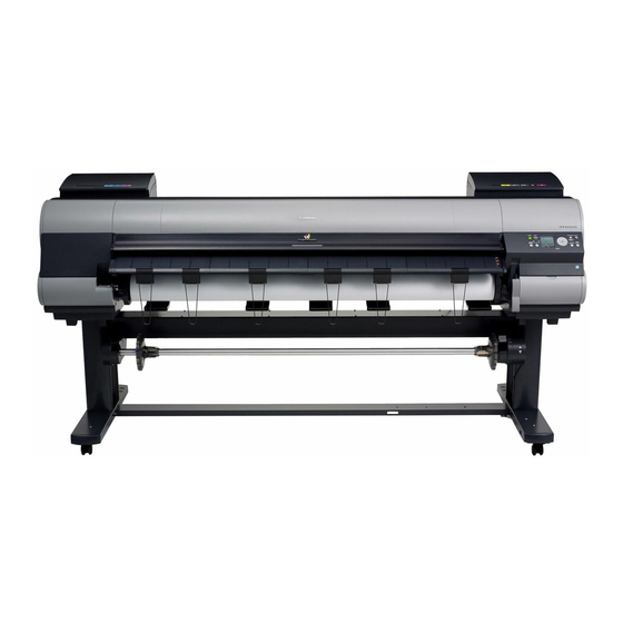
Canon iPF9000 series Service Manual (432 pages)
Brand:
Canon
| Category:
Printer
| Size: 16.91 MB
Table of Contents
Service Manual
1
Symbols Used
4
Table of Contents
7
Chapter 1 PRODUCT DESCRIPTION
13
Product Overview
17
Features
19
Printhead
19
Ink Tank
20
Ink Tank
21
Cutter Unit
22
Roll Holder
22
Stand
22
Media Take-Up Unit
23
Hard Disk Drive
24
Consumables
24
Product Specifications
27
General Specifications
27
Product Specifications
28
Product Specifications
29
Detailed Specifications
30
Printing Mode
30
Print Speed and Direction
31
Print Speed and Direction
38
Interface Specifications
44
Names and Functions of Components
45
Front
45
Rear
46
Top Cover (Inside)
47
Carriage
48
Ink Tank Cover (Inside)
48
Basic Operation
50
Operation Panel
50
Main Menu
51
Main Menu
66
Basket Unit
87
Safety and Precautions
93
Safety Precautions
93
Moving Parts
93
Adhesion of Ink
94
Electrical Parts
96
Other Precautions
97
Printhead
97
Ink Tank
98
Handling the Printer
99
Precautions When Servicing Printer
101
Confirming the Firmware Version
101
Disposing of the Lithium Battery
101
Notes on the Data Stored in the Printer
101
Precautions against Static Electricity
101
Precautions for Disassembly/Reassembly
101
Self-Diagnostic Feature
101
Chapter 2 TECHNICAL REFERENCE
105
Basic Operation Outline
109
Printer Diagram
109
Print Signal Sequence
111
Print Driving
113
Print Driving
115
Print Driving
117
Firmware
119
Operation Sequence at Power-On
119
Operation Sequence at Power-Off
120
Print Control
121
Print Control
129
Print Position Adjustment Function
136
Head Management
136
Printhead Overheating Protection Control
136
Pause between
136
White Raster Skip
136
Sleep Mode
136
Hard Disk Drive
136
Printer Mechanical System
138
Outline
138
Ink Passage
139
Overview of Ink Passage
139
Ink Tank Unit
140
Structure of Ink Tank Unit
140
Carriage Unit
142
Functions of Carriage Unit
142
Structure of Carriage Unit
143
Printhead
145
Structure of Printhead
145
Purge Unit
146
Functions of Purge Unit
146
Structure of Purge Unit
149
Maintenance Cartridge
151
Air Flow
152
Paper Path
153
Outline
153
Overview of Paper Path
153
Cutter Unit
154
Paper Path
154
Structure of Cutter Unit
154
Structure of Feed Roller Unit
154
Printer Electrical System
155
Outline
155
Overview
155
Main Controller
158
Main Controller PCB Components
158
Main Controller PCB Components
160
Carriage Relay PCB
162
Carriage Relay PCB Components
162
Head Relay PCB
162
Head Relay PCB Components
162
Head Relay PCB Components
163
Motor Driver
164
Media Take-Up PCB Components
164
Maintenance Cartridge Relay PCB
164
Maintenance Cartridge Relay PCB Components
164
Power Supply
164
Power Supply Block Diagram
164
Detection Functions with Sensors
165
Sensors for Covers
165
Ink Passage System
166
Carriage System
168
Paper Path System
170
Media Take-Up Unit
171
Others
171
Chapter 3 INSTALLATION
173
Installation
173
Installation
177
Making Pre-Checks
178
Making Pre-Checks
179
Unpacking and Installation
180
Checking the Contents
180
Checking the Contents
183
Assembling the Stand
186
Installing the Printer
189
Installing the Media Take-Up Unit
195
Installing the Basket
199
Removing Protection Materials
203
Checking the Images/Operations
205
Checking the Image and Operation
205
Transporting the Printer
206
Transporting the Printer
219
Reinstalling the Printer
232
Service Parts
239
Chapter 4 DISASSEMBLY/REASSEMBLY
240
Diassembly/Reassembly
240
Points to Note on Disassembly and Reassembly
243
Note on Locations Prohibited from Disassembly
243
Moving the Carriage Manually
243
Units Requiring Draining of Ink
243
External Covers
244
Drive Unit
251
Carriage Unit
252
Ink Tube Unit
256
Feeder Unit
258
Purge Unit
259
Ink Tank Unit
260
Linear Encoder
263
Head Management Sensor
264
Pcbs
265
Opening the Cap and Moving the Wiper Unit
266
Opening and Closing Ink Supply Valves
267
Draining the Ink
268
Applying the Grease
269
Adjustment and Setup Items
272
Adjustment Item List
272
Action to Take after Replacing the Carriage Unit or Multi Sensor
272
Action to Take after Replacing the Feed Roller Encoder or Feed Roller
272
Action to Take after Replacing the Head Management Sensor
272
Chapter 5 MAINTENANCE
275
Periodic Replacement Parts
279
Consumable Parts
279
Consumable Parts
280
Consumable Parts
281
Periodic Maintenance
282
Chapter 6 TROUBLESHOOTING
287
Troubleshooting
291
Outline
291
Outline of Troubleshooting
291
Troubleshooting When Warnings Occur
291
Check Maint Cartridge Capacity
291
Ink Level: Check
291
Ink Tank Is Empty. Replace the Ink Tank
291
No Ink Tank Loaded. Check Ink Tank
291
Check Printed Document
292
Close Ink Tank Cover
292
End of Paper Feed. Cannot Feed Paper more
292
GARO W12Xx
292
Paper Type Wrong
292
Parts Replacement Time Has Passed. Call for Service
293
Prepare for Parts Replacement. Call for Service
293
Troubleshooting When Errors Occur
293
03010000-200C/03010000-200E/03010000-200F/03010000-2017/03010000-2018/03016000-2010 Multi Sensor
293
03870001-2015 Cutter Error
293
03031000-2E0F Upper Cover Sensor Error
294
03031000-2E11 Carriage Cover Sensor Error
294
03031000-2E12 Defective Paper Release Lever
294
03031101-2E10 Ink Tank Cover Switch Error
294
03010000-200D Cut Media End Error
295
03010000-2E1F/03060000-2E14/03060A00-2E00/03061000-2E15/03063000-2E08/03860002-2E02/03860002-2E0A/ 03860002-2E0C Path Mismatch Error
295
03010000-2E1F/03060000-2E14/03060A00-2E00/03061000-2E15/03063000-2E08/03860002-2E02/03860002-2E0A/03860002-2E0C Path Mismatch Error
295
03862000-2E09 Insufficient Roll Media Error
295
E27 Paper Feed Error
295
03060A00-2E1B Roll Media End Error
296
03890000-2920 Media Take-Up Motor Error
296
03890000-2921 Media Take-Up Paper Detection Sensor Error
296
A/03830109-252B/03830108-252C Ink Tank Is Not Installed. ( this Error Occurs When the Ink Tank Is Replaced.)
297
Printhead)
297
When the Ink Tank Is Replaced.)
297
03800202-2813 Printhead Error
298
A/03810209-258B/03810208-258C Ink Low Error (Occures When Cleaning B Is Executed)
298
Executed)
298
Printhead Error
298
03130031-260E Gap Detection Error
299
03800501-280D/03800502-280E Defective Printhead Nozzle
299
03130031-260F Gap Adjustment Error
300
03130031-2618 VH Voltage Abnormality Error
300
03130031-2F16 Mist Fan Error
300
03130031-2F17 Suction Fan Error
300
03800500-2F2F/03800500-2F30 Head Management Sensor Error
300
03030000-2E21 IEEE1394 Error
301
03130031-2F1F/03130031-2F20 Defective Sensor in Purge Unit
301
03130031-2F25 Carriage Home Position Error
301
03130031-2F26/03130031-2F27 Carriage Motor Error
301
03130031-2F22/03130031-2F23/03130031-2F2D Purge Motor Driving Error
302
03130031-2F28 Lift Motor Time out Error
302
03130031-2F2A Feed Roller Home Position Error
302
03130031-2F2E Roll Media Feeding Error
302
03130031-2F3A Valve Open/Close Error
302
03130031-2F13 A/D Converter External Trigger Output Stopped
303
03130031-2F14 ASIC Register Cannot be Written
303
031A1001-2908/031A1006-2909 Hard Disk Error
303
031A1002-2905/031A1002-2906 Hard Disk Preservation Error
303
E194-4034 Sensor Calibration Error
303
Troubleshooting When Service Call Errors Occur
304
E141-4046 Recovery System's Count Error
304
E144-4047 Supply System's Count Error
304
E146-4001 Waste Ink Count Full
304
E161-403E/E161-403F Abnormally High Head Temperature
304
E194-404A Non-Discharge Detection Count Error
304
E196-4040/E196-4041/E196-4042/E196-4043/E196-4044/E196-4045 Main Controller PCB Error
305
E198-401C/E198-401D/E198-401E RTC Error
305
E602-401A HDD Failure
305
E602-401B HDD Connection Error
305
Location of Connectors and Pin Arrangement
305
Main Controller PCB
305
Main Controller PCB
317
Carriage Relay PCB
327
Head Relay PCB
336
Head Relay PCB
344
Version up
352
Firmware Update Tool
352
Service Tools
353
Tool List
353
Chapter 7 SERVICE MODE
355
Service Mode
359
Service Mode Operation
359
Map of the Service Mode
360
Map of the Service Mode
367
Map of the Service Mode
374
Details of Service Mode
381
Details of Service Mode
391
Details of Service Mode
401
Sample Printout
411
Sample Printout
415
Special Mode
419
Special Modes for Servicing
419
Chapter 8 ERROR CODE
421
Outline
425
Warning Table
425
Warnings
425
Error Table
427
Errors
427
Sevice Call Table
430
Service Call Errors
430
Advertisement
Advertisement
Related Products
Canon iPF9000 - imagePROGRAF Color Inkjet Printer
Canon imagePROGRAF IPF9000S
Canon imagePROGRAF IPF9100
Canon imagePROGRAF iPF9400
Canon imagePROGRAF iPF9400S
Canon iPF9410
Canon image Prograf iPF780 Series
Canon iPF760 series
Canon iPF6410SE
Canon imagePROGRAF iPF815
Canon Categories
Printer
Digital Camera
All in One Printer
Camcorder
Scanner
More Canon Manuals
Login
Sign In
OR
Sign in with Facebook
Sign in with Google
Upload manual
Upload from disk
Upload from URL