Sign In
Upload
Manuals
Brands
Dell Manuals
Controller
DCL and 3
Dell DCL and 3 Manuals
Manuals and User Guides for Dell DCL and 3. We have
1
Dell DCL and 3 manual available for free PDF download: User Manual
Dell DCL and 3 User Manual (254 pages)
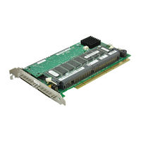
Expandable RAID Controller
Brand:
Dell
| Category:
Controller
| Size: 1.33 MB
Table of Contents
Safety Instructions
3
Table of Contents
9
1 Overview
25
PERC 3 Overview
26
PERC 3 Features
26
SCSI Channels
27
Non-Volatile Random Access Memory (NVRAM) and Flash Read-Only Memory (ROM)
27
SCSI Connectors
27
Single-Ended and LVD SCSI Buses
28
Maximum Cable Length for SCSI Standards
28
SCSI Bus Widths and Maximum Throughput
28
Table 1-1. Maximum Cable Length for SCSI Standards
28
Table 1-2. SCSI Bus Widths and Maximum Throughput
28
Operating System Support
29
2 Introduction to RAID
31
RAID Definition
32
PERC 3 Host-Based RAID Solution
32
Components and Features
33
Physical Array
33
Logical Drive
33
Fault Tolerance
33
Consistency Check
34
Disk Striping
34
Figure 2-1. Example of Disk Striping
35
Disk Mirroring
36
Figure 2-2. Example of Disk Mirroring
36
Disk Spanning
37
Figure 2-3. Example of Disk Spanning
37
Spanning for RAID 10 or RAID 50
38
Parity
38
Table 2-1. Spanning for RAID 10 and RAID 50
38
Table 2-2. Types of Parity
38
Hot Spares
39
Figure 2-4. Example of Parity
39
Disk Rebuilds
40
Hot Swap
41
SCSI Drive States
41
Table 2-3. SCSI Drive States
41
Logical Drive States
42
Enclosure Management
42
Table 2-4. Logical Drive States
42
3 RAID Levels
44
Overview
44
Selecting a RAID Level
44
Table 3-1. RAID Levels
44
Raid 0
45
Table 3-2. RAID 0 Overview
45
Figure 3-1. RAID 0 Array
46
Raid 1
47
Table 3-3. RAID 1 Overview
47
Raid 5
48
Figure 3-2. RAID 1 Array
48
Table 3-4. RAID 5 Overview
49
Raid 10
50
Figure 3-3. RAID 5 Array
50
Table 3-5. RAID 10 Overview
51
Raid 50
52
Figure 3-4. RAID 10 Array
52
Table 3-6. RAID 50 Overview
53
Figure 3-5. RAID 50 Array
54
4 PERC 3/SC Features
55
Hardware Requirements
56
Configuration Features
56
Table 4-1. Configuration Features
56
Configuration on Disk Configuration
57
SMART Technology
57
Table 4-2. Configuration on Disk Features
57
Hardware Architecture Features
58
Array Performance Features
58
Table 4-3. Hardware Architecture Features
58
Table 4-4. Array Performance Features
58
PERC 3/SC Fault Tolerance Features
59
Software Utilities
59
Table 4-5. PERC 3/SC Fault Tolerance Features
59
Table 4-6. Software Utilities Features
59
Operating System Software Drivers
60
PERC 3/SC Specifications
60
Table 4-7. PERC 3/SC Specifications
60
Cache Memory
61
PCI Bridge/Cpu
61
Onboard Speaker
62
Perc 3/Sc Bios
62
SCSI Bus
62
SCSI Connectors
62
SCSI Termination
62
Serial Port
62
RAID Management
63
SCSI Firmware
63
Table 4-8. SCSI Firmware Support
63
5 PERC 3/DC and PERC 3/DCL Features
66
Hardware Requirements
66
Configuration Features
66
Table 5-1. Configuration Features
66
Configuration on Disk
67
SMART Technology
67
Table 5-2. Configuration on Disk Features
67
Hardware Architecture Features
68
Table 5-3. Hardware Architecture Features
68
Array Performance Features
69
Fault Tolerance Features
69
Table 5-4. Array Performance Features
69
Table 5-5. Fault Tolerance Features
69
Software Utilities
70
Operating System Software Drivers
70
PERC 3/DC and PERC 3/DCL Specifications
70
Table 5-6. Software Utilities
70
Table 5-7. PERC 3/DC and PERC 3/DCL Specifications
70
PCI Bridge/Cpu
71
Cache Memory
72
Onboard Speaker
72
PERC 3/DC and PERC 3/DCL BIOS
72
SCSI Bus
72
Serial Port
72
SCSI Connectors
73
SCSI Firmware
73
SCSI Termination
73
Table 5-8. SCSI Firmware
73
RAID Management
74
6 PERC 3/QC Features
75
Hardware Requirements
76
Configuration Features
76
Table 6-1. Configuration Features
76
Configuration on Disk
77
SMART Technology
77
Table 6-2. Configuration on Disk Features
77
Hardware Architecture Features
78
Array Performance Features
78
Table 6-3. Hardware Architecture Features
78
Table 6-4. Array Performance Features
78
Fault Tolerance Features
79
Software Utilities
79
Table 6-5. Fault Tolerance Features
79
Operating System Software Drivers
80
PERC 3/QC Specifications
80
Table 6-6. Software Utilities
80
Table 6-7. PERC 3/QC Specifications
80
Cache Memory
81
PCI Bridge/Cpu
81
Onboard Speaker
82
Perc 3/Qc Bios
82
SCSI Bus
82
SCSI Connectors
82
SCSI Termination
82
Serial Port
82
RAID Management
83
SCSI Firmware
83
Table 6-8. SCSI Firmware
83
100 C O N F I G U R I N G P E R C 3
85
Configuring SCSI Physical Drives
86
Current Configuration
86
Table 7-1. Current Configuration for SCSI Channel 0
87
Table 7-2. Current Configuration for SCSI Channel
87
Table 7-3. Current Configuration for SCSI Channel
88
Logical Drive Configuration
89
Table 7-4. Current Configuration for SCSI Channel
89
Table 7-5. Logical Drive Configuration
89
Physical Device Layout
91
Table 7-6. Physical Device Layout
91
Configuring Arrays
94
Arranging Arrays
95
Creating Hot Spares
95
Creating Logical Drives
95
Configuration Strategies
95
Maximizing Capacity
96
Maximizing Drive Availability
96
Table 7-7. Drives and Capacities for each RAID Level
96
Table 7-8. Fault Tolerance Features for RAID Levels 0, 1 and
96
Maximizing Drive Performance
97
Assigning RAID Levels
97
Table 7-9. Performance Characteristics for each RAID Level
97
Table 7-10. Physical Drives Required for each RAID Level
97
Configuring Logical Drives
98
Optimizing Data Storage
98
Data Access Requirements
98
Array Functions
99
Planning the Array Configuration
99
Table 7-11. Factors to Consider for Array Configuration
99
Table 7-12. Array Configuration Planner
100
Using the Array Configuration Planner
100
Random Array Deletion
101
Overview
101
Configuration Module
102
8 PERC 3/SC Hardware Installation
103
Requirements
104
Optional Equipment
104
PERC 3/SC Card Layout
105
Installation Steps
105
Figure 8-1. PERC 3/SC Card Layout
105
Step 1-Unpack
106
Step 2-Power down
106
Step 3-Set Jumpers
107
Table 8-1. PERC 3/SC Jumpers
107
Table 8-2. J1 Termination Enable Settings
107
Table 8-3. J9 I2C Interface Connector Pinout
108
Table 8-4. J5 Serial Port Pinout
108
Table 8-5. J8 Hard Disk LED
109
Table 8-6. J15 RUBI Slot Interrupt Steering
109
Figure 8-2. Example of SCSI Termination
110
Step 4-Set SCSI Termination
110
Table 8-7. J16, J17 RUBI Slot Interrupt Steering
110
Figure 8-3. Termination of Internal SCSI Disk Arrays
112
Figure 8-4. PCI Slots on Motherboard
113
Step 5-Install PERC 3/SC
113
Figure 8-5. Installation of PERC 3/SC Card into Motherboard
114
Figure 8-6. Connecting SCSI Cables
115
Step 6-Connect SCSI Cables
115
Step 7-Set Target Ids
116
Step 8-Power on Host System
117
Table 8-8. Target Ids
117
Step 10-Install Operating System Software Drivers
118
Step 9-Run PERC 3 BIOS Configuration Utility or Webbios Utility
118
9 PERC 3/DC or PERC 3/DCL Hardware Installation
120
Requirements
120
Optional Equipment
120
PERC 3/DC Card Layout
121
Figure 9-1. PERC 3/DC Card Layout
121
PERC 3/DCL Card Layout
122
Installation Steps
122
Figure 9-2. PERC 3/DCL Card Layout
122
Step 1-Unpack the PERC 3/DC or PERC 3/DCL
123
Step 2-Power down
123
Step 3-Set Jumpers
123
Table 9-1. Jumper Settings
123
Table 9-2. J2 and J3 Termination Enable Settings
124
Table 9-3. J9 Onboard BIOS Enable Settings
124
Figure 9-3. J11 Serial Port Pinout
125
Table 9-4. J10 NVRAM Clear Pinout
125
Table 9-5. J11 Serial Port Pinout
125
Table 9-6. J13 Dirty Cache LED Pinout
126
Table 9-7. J14 SCSI Activity Pinout
126
Table 9-8. J16 and J18 TERMPWR Enable Settings
126
Step 4-Set SCSI Termination
127
Table 9-9. J17 I2C Connector Pinout
127
Step 5-Install the PERC 3/DC or PERC 3/DCL Controller
128
Figure 9-5. Installation of the PERC 3/DC and 3/DCL
129
Step 6-Select and Set Target Ids for SCSI Devices
130
Step 7-Connect SCSI Cables
130
Table 9-10. Target Ids for SCSI Devices
130
Figure 9-6. Connecting SCSI Cables to PERC 3/DC and 3/DCL
131
Step 8-Power on Host System
132
Step 9-Run the PERC 3 BIOS Configuration Utility or Webbios Configuration Utility
132
Step 10-Install Operating System Software Driver
133
Replacing a PERC 3/DC Containing a BC Chip with a PERC 3/DC Containing a be Chip
133
Using Driver 5.22.1 or 5.22.2 and Firmware 161J or 161N
133
Using Driver 5.30 and Firmware 1.70
133
10 PERC 3/QC Hardware Installation
135
Requirements
136
Optional Equipment
136
PERC 3/QC Card Layout
137
Figure 10-1. PERC 3/QC Card Layout
137
Installation Steps
138
Step 1-Unpack the PERC 3/QC Controller
138
Step 2-Power down
139
Step 3-Set Jumpers
139
Table 10-1. PERC 3/QC Jumper Settings
139
Table 10-2. J2, J3, J5 and J7 Termination Enable Pinout
140
Table 10-3. J9, J10, J11 and J12 TERMPWR Enable Pinout
140
Figure 10-2. J14 Serial Port Diagram
141
Table 10-4. J14 Serial Port Pinout
141
Table 10-5. J17 Dirty Cache LED Pinout
141
Step 4-Set SCSI Termination
142
Table 10-6. J19 Onboard BIOS Enable Settings
142
Table 10-7. J23 External Battery Pinout
142
SCSI Termination
143
Figure 10-3. Example of Termination
143
Figure 10-4. Termination of Internal SCSI Disk Arrays
144
Step 5-Install PERC 3/QC
145
Figure 10-5. PCI Slots on Motherboard
145
Figure 10-6. Installation of the PERC 3/QC Card
146
Step 6-Connect SCSI Cables
147
Figure 10-7. Connecting SCSI Cables
147
Step 7-Set Target Ids
148
Step 8-Power on Host System
148
Table 10-8. Target Ids
148
Step 9-Run the PERC 3 BIOS Configuration Utility or Webbios Configuration Utility
149
Step 10-Install Operating System Driver
149
11 PERC 3 BIOS Configuration Utility
151
Configuration on Disk
152
Starting the PERC 3 BIOS Configuration Utility
152
BIOS Configuration Utility Menu Options
153
Table 11-1. BIOS Configuration Utility Menu Options
153
Configure Menu
154
Table 11-2. Configuration Menu Options
154
Initialize Menu
155
Objects Menu
155
Table 11-3. Adapter Menu Options
155
Table 11-4. Logical Drive Menu Options
157
Table 11-5. Physical Drive Menu Options
158
Table 11-6. SCSI Channel Menu Options
159
Table 11-7. Battery Information Menu Options
159
Format Menu
160
Rebuild Menu
160
Check Consistency Menu
161
Configuring Arrays and Logical Drives
161
Choosing the Configuration Method
162
Easy Configuration
162
New Configuration
162
View/Add Configuration
163
PERC 3/QC and PERC 3/DC Default Settings
163
PERC 3/SC and PERC 3/DCL Default Settings
163
Table 11-8. PERC 3/QC and PERC 3/DC Default Settings
163
Table 11-9. PERC 3/SC and PERC 3/DCL Default Settings
163
Reserved Disk Space During Configuration
164
Designating Drives as Hot Spares
164
Using Easy Configuration
165
Using New Configuration
169
Using View/Add Configuration
175
Initializing Logical Drives
180
Batch Initialization
180
Individual Initialization
181
Deleting Logical Drives (Random Array Deletion)
181
Formatting Physical Drives
182
Media Errors
182
Formatting Drives
182
Rebuilding Failed Disk Drives
184
Manual Rebuild - Rebuilding an Individual Drive
184
Manual Rebuild - Batch Mode
184
Table 11-10. Rebuild Types
184
Using a Pre-Loaded SCSI Drive "As-Is
185
Exiting the PERC 3 BIOS Configuration Utility
186
Setting Hardware Termination
186
Clustering
187
Cluster Mode
187
Enabling and Disabling the Cluster Mode
187
12 Dell Manager
189
Starting Dell Manager
190
Table 12-1. Command Used to Start Dell Manager
190
Management Menu Options
191
Table 12-2. Management Menu Options
191
Using Dell Manager in Red hat Linux GUI Mode
191
Dell Manager Menu Options
192
Initialize Menu
192
Objects Menu
192
Table 12-3. Adapter Menu Options
192
Table 12-4. Logical Drive Menu Options
193
Table 12-5. Logical Drive Default Settings
193
Table 12-6. Physical Drive Menu Options
194
Table 12-7. SCSI Channel Options
195
Table 12-8. Battery Backup Menu Items
195
Format Menu
196
Rebuild Menu
197
Check Consistency Menu
197
Reconstruct Menu
197
Designating Drives as Hot Spares
197
Parameters
198
Initializing Logical Drives
199
Batch Initialization
199
Individual Initialization
200
Deleting Logical Drives (Random Array Deletion)
200
Formatting Physical Drives
201
Media Errors
201
Formatting Drives
202
Rebuilding Failed Disk Drives
203
Manual Rebuild - Rebuilding an Individual Drive
203
Table 12-9. Rebuild Types
203
Manual Rebuild - Batch Mode
204
Exiting Dell Manager
204
13 Troubleshooting
205
Overview
206
Table 13-1. General Problems and Suggested Solutions
206
BIOS Boot Error Messages
207
Table 13-2. BIOS Boot Error Messages
207
Other BIOS Error Messages
210
Table 13-3. Other BIOS Error Messages
210
Other Potential Problems
211
Table 13-4. Other Potential Problems
211
Audible Warnings
212
Table 13-5. Audible Warnings
212
Advertisement
Advertisement
Related Products
Dell Axim X5 400MHz - Axim X5 - Win Mobile
Dell Vostro A90
Dell A940 All In One Personal Printer
Dell Alienware 17
Dell Alienware Series
Dell AirWave Wireless Management Suite
Dell Alienware Aurora R7
Dell Alienware AW2521H
Dell Alienware AW2523HF
Dell APL29-0B6
Dell Categories
Laptop
Desktop
Server
Monitor
Storage
More Dell Manuals
Login
Sign In
OR
Sign in with Facebook
Sign in with Google
Upload manual
Upload from disk
Upload from URL