Sign In
Upload
Manuals
Brands
Fujitsu Manuals
Server
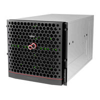
PRIMEQUEST 2800E3
Fujitsu PRIMEQUEST 2800E3 Manuals
Manuals and User Guides for Fujitsu PRIMEQUEST 2800E3. We have
2
Fujitsu PRIMEQUEST 2800E3 manuals available for free PDF download: General Description Manual, Design Manual
Fujitsu PRIMEQUEST 2800E3 General Description Manual (148 pages)
Brand:
Fujitsu
| Category:
Server
| Size: 4.94 MB
Table of Contents
General Description
1
Revision History
4
Alert Messages in the Text
5
Safety Precautions
5
About this Product
8
How to Use this Manual
9
Support and Service
9
Command Syntax
13
Table of Contents
15
CHAPTER 1 Product Overview
24
Introduction of the PRIMEQUEST 2000 Series
24
PRIMEQUEST 2400E3/2800E3/2800B3 Features
24
PRIMEQUEST 2400E2/2800E2/2800B2 Features
25
PRIMEQUEST 2400E/2800E/2800B Features
26
Product Lineup
28
FIGURE 1.1 External Overview of 2400E3/2800E3/2400E2/2800E2/2400E/2800E
28
FIGURE 1.2 External Overview of 2800B3/2800B2
29
FIGURE 1.3 External Overview of 2800B
29
PRIMEQUEST 2000 Series Configuration
30
FIGURE 1.4 Configuration Conceptual Diagram
30
FIGURE 1.5 Hardware Configuration Image (PRIMEQUEST 2400E3/2400E2/2400E)
31
Hardware Configuration
31
FIGURE 1.6 Hardware Configuration Image (PRIMEQUEST 2800E3/2800E2/2800E)
32
FIGURE 1.7 Hardware Configuration Image (PRIMEQUEST 2800B3/2800B2/2800B)
33
Hardware Specifications
34
TABLE 1.1 Hardware Specifications (PRIMEQUEST 2400E3/2800E3/2800B3)
34
TABLE 1.2 Hardware Specifications (PRIMEQUEST 2400E2/2800E2/2800B2)
35
TABLE 1.3 Hardware Specifications (PRIMEQUEST 2400E/2800E/2800B)
36
Hardware Management
38
Partition Management
38
Hardware Technologies
38
Cpu
41
Quickpath Interconnect (QPI)
42
Hyper Threading Technology Function
42
Memory Mirror Functions
42
Memory Sparing Function
43
Reserved SB Function
43
Table 1.4 Available Memory Mirror Mode
43
Hardware RAID
44
PCI Hot Plug Function
44
Security and Encryption Function
44
Trusted Platform Module (TPM)
44
TABLE 1.5 Hardware RAID Level
44
Secure Boot
45
Physical Partitioning (PPAR)
45
Extended Partitioning
45
Extended Socket
45
Dynamic Reconfiguration (DR) Function
45
Flexible I/O
46
Memory Scale-Up Board
46
Virtual Support Virtualization Technology (VT) Function
46
Management Board (MMB)
46
Table 1.6 Vt
46
Network (LAN)
47
Preboot Execution Environment (PXE)
48
TABLE 1.7 PXE Boot Support
48
Iscsi Boot and Iscsi Connection
49
TABLE 1.8 Iscsi Boot
49
TABLE 1.9 Iscsi Connections
49
Fcoe Boot and Fcoe Connection
50
TABLE 1.10 Fcoe Boot
50
TABLE 1.11 Fcoe Connections
50
Virtualization Function of FC Card
51
Wake on LAN (WOL)
51
Sadump
51
Green Support and Power Saving Technology
51
TABLE 1.12 WOL Support
51
Active Processor Cores Function
52
Optimal Fan Control Cooling (Optimization of Rotation Per Minute of Fans)
52
Air Flow Monitoring
52
Optimal Power Allocation (Optimization of the Number of Operation Power Sources)
52
TABLE 1.13 Active Processor Cores Specifications
52
Power Consumption Monitoring
53
Power Saving
53
Agentless Monitoring
53
LDAP Function (Lightweight Directory Access Protocol)
53
Software Technologies
53
Firmware
53
TABLE 1.14 Power Consumption Monitoring Support
53
Operating System and Virtualization Software
54
Server Management Software
55
FIGURE 1.8 Configuration Diagram of the PRIMEQUEST 2000 Series Operation Management
56
FIGURE 1.9 SVIM Setup Flow
56
Fujitsu Middleware Products
58
Clustering
58
CHAPTER 2 Hardware Configuration
59
Components
59
TABLE 2.1 Maximum Installation Number of Components
59
Base Cabinet
61
FIGURE 2.1 PRIMEQUEST 2400E3/2800E3/2400E2/2800E2 Front View
61
FIGURE 2.2 PRIMEQUEST 2400E/2800E Front View
61
FIGURE 2.3 PRIMEQUEST 2400E3/2800E3/2400E2/2800E2/2400E/2800E Rear View
62
FIGURE 2.4 PRIMEQUEST 2400E3/2800E3/2400E2/2800E2/2400E/2800E Top View
62
FIGURE 2.5 PRIMEQUEST 2400E3/2800E3/2400E2/2800E2/2400E/2800E Right View
62
FIGURE 2.6 PRIMEQUEST 2400E3/2800E3/2400E2/2800E2/2400E/2800E Perspective View
63
FIGURE 2.7 PRIMEQUEST 2800B3/2800B2 Front View
63
FIGURE 2.8 PRIMEQUEST 2800B Front View
64
FIGURE 2.9 PRIMEQUEST 2800B3/2800B2/2800B Rear View
64
FIGURE 2.10 PRIMEQUEST 2800B3/2800B2/2800B Top View
65
FIGURE 2.11 PRIMEQUEST 2800B3/2800B2/2800B Right View
65
FIGURE 2.12 PRIMEQUEST 2800B3/2800B2 Perspective View
65
Cpu
66
Support CPU List
66
FIGURE 2.13 PRIMEQUEST 2800B Perspective View
66
TABLE 2.2 Available CPU (PRIMEQUEST 2400E3/2800E3/2800B3)
66
DIMM (Memory Module)
67
Supported DIMM
67
DIMM Slot Locations
67
TABLE 2.3 Available CPU (PRIMEQUEST 2400E2/2800E2/2800B2)
67
TABLE 2.4 Available CPU (PRIMEQUEST 2400E/2800E/2800B)
67
DIMM Installation Group
68
SB (System Board)
68
SB Specifications
68
TABLE 2.5 SB Specifications (PRIMEQUEST 2400E3/2800E3/2800B3)
68
TABLE 2.6 SB Specifications (PRIMEQUEST 2400E2/2800E2/2800B2)
68
TABLE 2.7 SB Specifications (PRIMEQUEST 2400E/2800E/2800B)
69
FIGURE 2.14 SB External View (2400E3/2800E3/2400E2/2800E2)
70
FIGURE 2.15 SB External View (2800B3/2800B2)
71
FIGURE 2.16 SB External View (2400E/2800E)
72
FIGURE 2.17 SB External View (2800B)
73
Usb
74
FIGURE 2.18 System Diagram
74
Vga
75
Memory Scale-Up Board
75
Memory Scale-Up Board Specifications
75
TABLE 2.8 Memory Scale-Up Board Specifications
75
MMB (Management Board)
76
FIGURE 2.19 Memory Scale-Up Board External View
76
MMB Specifications
77
TABLE 2.9 MMB Specifications
77
FIGURE 2.20 External View of the MMB
78
MMB LAN Interface
78
MMB Serial Interface
78
IOU (IO Unit)
79
IOU (Iou_1Gbe/Iou_10Gbe) Specifications
79
TABLE 2.10 (Iou_1Gbe/Iou_10Gbe) Specifications
79
TABLE 2.11 the Specification of the IOU Built-In LAN Controller
79
FIGURE 2.21 External View of Iou_1Gbe
80
IOU Card Slot
81
DU (Disk Unit)
81
FIGURE 2.22 External View of Iou_10Gbe
81
TABLE 2.12 Connection of IOU with du
81
DU Specifications
82
FIGURE 2.23 du Conceptual Diagram
82
TABLE 2.13 du Specifications
82
Internal Storage Device
83
FIGURE 2.24 External View of the du
83
Internal HDD (Hard Disk Drive)
84
TABLE 2.14 HDD Bays in the SB and the HDD Specifications of the du
84
2400E3/2800E3/2800B3/2400E2/2800E2/2800B2)
84
TABLE 2.15 HDD Bays in the SB and the HDD Specifications of the du (PRIMEQUEST 2400E/2800E/2800B)
84
TABLE 2.16 the HDD Capacity in Maximum Configuration, and the Maximum LUN Capacity in a RAID Configuration
84
Internal SSD
85
OPL (Operator Panel)
85
TABLE 2.18 the SSD Capacity in Maximum Configuration and the Maximum LUN Capacity in a RAID Configuration
85
FIGURE 2.25 External View of OPL
86
OPL Specifications
87
Pci_Box
87
Pci_Box Specification
87
Pci_Box Interface
87
TABLE 2.19 OPL Specifications
87
TABLE 2.20 Pci_Box Specification
87
FIGURE 2.26 Pci_Box Conceptual Diagram
88
Pci_Box External View
89
FIGURE 2.27 Orthographic View of the Pci_Box Cabinet
89
FIGURE 2.28 Perspective Views of the Pci_Box Cabinet
89
Pci_Box Block Diagram
90
Pci_Box Component List
90
Pci_Box Connection Pattern
90
FIGURE 2.29 Pci_Box Block Diagram
90
TABLE 2.21 Pci_Box Components
90
TABLE 2.22 Number of Connectable Pci_Boxes
90
FIGURE 2.30 Pci_Box Connection Diagram (Maximum Configuration) for Mounted Four Iou_1Gbes
91
FIGURE 2.31 Pci_Box Connection Diagram (Maximum Configuration) for Mounted Four Iou_10Gbes
91
PCI _Box Connection Conditions
92
FIGURE 2.32 Straight Connection (Permitted)
92
FIGURE 2.33 Crossover Connection (Permitted)
92
FIGURE 2.34 Connection to Different Pci_Boxes Pattern 1 (Permitted)
93
FIGURE 2.35 Connection to Different Pci_Boxes Pattern 2 (Permitted)
93
FIGURE 2.36 Connection from Iou_1Gbe and Iou_10Gbe (Permitted)
93
Pci_Box Number
94
PCI Express Slot
94
PCI Express Slot (IOU) Specifications
94
FIGURE 2.37 Pci_Box Shared by Different PRIMEQUEST Cabinet (Not Permitted)
94
TABLE 2.23 Usable Number of PCI Express Slots in Maximum Configuration
94
TABLE 2.24 PCI Express Slot (IOU) Specifications
94
PCI Express Slot (Pci_Box) Specifications
95
PCI Express Cassette
95
Middle Plane (MP)
95
Power Supply Unit (PSU)
95
TABLE 2.25 PCI Express Slot (Pci_Box) Specifications
95
FIGURE 2.38 External View of the PSU
96
PSU_P Specifications
96
TABLE 2.26 PSU_P Specifications
96
AC Cable Specifications
97
Dual Power Feed Configuration
97
Mounting Conditions When Using 100V Power Supply
97
Number of Psus Required
97
PSU_S Specifications
97
Fan (Cooling Mechanism)
97
TABLE 2.27 PSU_S Specifications
97
CHAPTER 3 Software Configuration
98
Bundled Electronic Media
98
Bundled Software
99
Supplied Drivers
99
TABLE 3.1 List of Bundled Software
99
Firmware
100
Operations Management Software
100
CHAPTER 4 Functions Provided by the PRIMEQUEST 2000 Series
101
Basic Architecture
101
Management with MMB
101
MMB Functions
101
FIGURE 4.1 Basic Architecture
101
MMB Firmware
102
User Account Management of MMB
102
FIGURE 4.2 Access to MMB in Local User Management (LDAP Is Disable)
102
MMB Operating Environment
103
FIGURE 4.3 Access to MMB in Global User Management (LDAP Is Enabled)
103
Hardware Monitoring and Configuration Display
104
FIGURE 4.4 [System Status] Screen (Example of Configuration Display Screen)
104
Partition Settings and Configuration Display
105
REMCS (Automatic Notification Function)
105
FIGURE 4.5 Example of Mounting Different os and Versions on each Partition
105
Saving and Restoring System Settings Information
106
Power Supply Monitoring and Control
106
PSU Configuration
106
FIGURE 4.6 REMCS (Automatic Report Function)
106
TABLE 4.1 Power Supply Pattern
106
Power Consumption Monitoring
107
TABLE 4.2 PSU Mounting Location (PRIMEQUEST 2400E3/2400E2/2400E) (*1)
107
TABLE 4.3 PSU Mounting Location (PRIMEQUEST 2800E3/2800B3/2800E2/2800B2/2800E/2800B)
107
Optimal Power Allocation
108
Scheduled Operations
108
Remote Power Supply Operations
108
Ups
108
Clock Feature
108
MMB, BIOS and BMC Time Management
108
NTP Client
109
FIGURE 4.7 Diagram of Time Synchronization (of Three 3 NTP Servers)
109
Proactive Monitoring
110
Video Redirection
111
FIGURE 4.8 Flow of Proactive Monitoring
111
Console Redirection
112
Virtual Media
112
Sadump
112
Sadump Firmware
112
Memory Dump Function (Linux)
112
FIGURE 4.9 Sadump Conceptual Diagram
112
Memory Dump Function (Windows)
113
CHAPTER 5 Partitioning
114
Partitioning Function
114
Physical Partitioning (PPAR)
114
TABLE 5.1 Maximum Number of Partitions for each Model (PPAR)
114
FIGURE 5.1 Conceptual Diagram of the Partitioning (PRIMEQUEST 2400E3/2400E2)
115
FIGURE 5.2 Conceptual Diagram of the Partitioning (PRIMEQUEST 2400E)
115
FIGURE 5.3 Conceptual Diagram of the Partitioning (PRIMEQUEST 2800E3/2800E2/2800E)
116
Partition Granularity
116
TABLE 5.2 Partition Granularity of Components Making up a Partition (PPAR)
116
TABLE 5.3 Relationship between du and IOU Connection
116
Partition Configuration Rule
117
Extended Partitioning
117
Partition Granularity of the Extended Partitioning
117
Use Conditions of the Extended Partitioning
117
TABLE 5.4 Partition Configuration Rule (Component)
117
TABLE 5.5 Partition Granularity of each Component that Makes up the Partition (Extended Partitioning)
117
Configuration Rules of the Extended Partitioning
118
Extended Socket
118
Memory Scale-Up Board
118
Reserved SB
118
TABLE 5.6 Minimum and Maximum Configuration of Extended Partitioning
118
Partition Configuration Definition Method
119
Notes on the Partition Configuration
119
Dynamic Reconfiguration Function
119
Flexible I/O Mode
119
FIGURE 5.4 [Partition Configuration] Screen
119
Home SB
120
FIGURE 5.5 Conceptual Diagram of Flexible I/O
120
CHAPTER 6 Redundancy
122
Redundancy
122
Redundancy of Components
122
Redundancy of HDD
122
Redundancy of the Disk
122
TABLE 6.1 System Disk Redundancy
122
Redundancy of the Management LAN
123
Operation LAN Redundancy
123
Degradation Function
123
CHAPTER 7 Applicable Components for Hot Maintenance
124
Overview of Hot Maintenance
124
List of Components
124
CHAPTER 8 Operations Management Tools
125
Overview of Operations Management Tools
125
Mmb
125
Graphical User Interface (GUI)
125
FIGURE 8.1 Overall Configuration Diagram of the Operations Management Tools
125
Command Line Interface (CLI)
126
Video Redirection
126
Console Redirection
126
Virtual Media
126
Serverview Suite (SVS)
126
TABLE 8.1 List of SVS Function Manuals
127
Uefi
128
CHAPTER 9 Server Maintenance
129
Maintenance Policy / Preventive Maintenance
129
Notes on Maintenance
129
Firmware Setting Information
129
Logs Collected by the MMB
129
FIGURE 9.1 [System Event Log] Screen
130
CHAPTER 10 Hardware Installation and Connection
131
Appendix A Component Mounting Locations
132
Appendix B Mounting Locations, BUS Numbers, and Slot Numbers
133
Appendix C Status Checks with Leds
134
Appendix D Component Mounting Conditions
135
Appendix E Cable Specifications
136
Appendix F Tree Structure of the MIB Provided with the PRIMEQUEST 2000 Series
137
Appendix G Linkage Functions and Services
138
Linkage with Systemwalker Centric Manager
138
Remote Customer Support System (REMCS)
138
Appendix H Right or Wrong of Combination of each Function
139
Right or Wrong of Combination of each Function in Microsoft ® Windows Server ® 2012 R2
139
Table H.1 Right or Wrong of Combination of each Function in Microsoft ® Windows Server ® 2012 R2
139
Right or Wrong of Combination of each Function in Microsoft ® Windows Server ® 2012
140
Table H.2 Right or Wrong of Combination of each Function in Microsoft ® Windows Server ® 2012
140
Right or Wrong of Combination of each Function in Microsoft ® Windows Server ® 2008 R2 (64Bit)
141
Table H.3 Right or Wrong of Combination of each Function in Microsoft ® Windows Server ® 2008 R2 (64Bit)
141
Right or Wrong of Combination of each Function in Vmware Vsphere ® 6
142
Table H.4 Right or Wrong of Combination of each Function in Vmware Vsphere ® 6
142
Right or Wrong of Combination of each Function in Vmware Vsphere ® 5
143
Table H.5 Right or Wrong of Combination of each Function in Vmware Vsphere ® 5
143
Right or Wrong of Combination of each Function in Red hat ® Enterprise Linux ® 7 (for Intel64)
144
Table H.6 Right or Wrong of Combination of each Function in Red hat ® Enterprise Linux ® 7 (for Intel64)
144
Right or Wrong of Combination of each Function in Red hat ® Enterprise Linux ® 6 (for Intel64)
145
Table H.7 Right or Wrong of Combination of each Function in Red hat ® Enterprise Linux ® 6 (for Intel64)
145
Right or Wrong of Combination of each Function in Novell ® SUSE® LINUX Enterprise Server 12
146
Table H.8 Right or Wrong of Combination of each Function in Novell ® SUSE® LINUX Enterprise Server 12
146
Right or Wrong of Combination of each Function in Novell ® SUSE® LINUX Enterprise Server 11 Service Pack 3
147
Table H.9 Right or Wrong of Combination of each Function in Novell ® SUSE® LINUX Enterprise Server 11 Service Pack 3
147
Advertisement
Fujitsu PRIMEQUEST 2800E3 Design Manual (137 pages)
2000 series
Brand:
Fujitsu
| Category:
Server
| Size: 4.29 MB
Table of Contents
Table of Contents
2
Preface
3
About this Manual
3
PRIMEQUEST Overview
6
Product Lineup
7
Component Names
11
Basic Configuration
12
Memory Mirror Function
22
Hot Plug
25
Boot Devices
25
Basic Hardware Configuration
28
System Fru
29
Pci Box Connection Conditions
53
Warranty Period
55
Power Supply Configuration
56
Sales Representative
59
Hardware Configuration Design
62
Key Points for Mmb Design
63
Redundant Configuration
63
Key Points for Hardware Partitioning Design
64
Configuration Example
64
Dynamic Reconfiguration Function
74
Supported Functions
74
Network Configuration
89
Management Lan
98
Power Supply Redundancy
111
Operation Management Design
115
Optional Products
121
Key Points for Ntp Operation
122
Os/Support
123
Advertisement
Related Products
Fujitsu PRIMEQUEST 2800B3
Fujitsu primequest 2800B2
Fujitsu primequest 2800E2
Fujitsu PRIMEQUEST 2800E
Fujitsu PRIMEQUEST 2800B
Fujitsu PRIMEQUEST 2400E3
Fujitsu 2737
Fujitsu 2742
Fujitsu 2616
Fujitsu primequest 2400E2
Fujitsu Categories
Air Conditioner
Laptop
Server
Scanner
Storage
More Fujitsu Manuals
Login
Sign In
OR
Sign in with Facebook
Sign in with Google
Upload manual
Upload from disk
Upload from URL