Sign In
Upload
Manuals
Brands
GE Manuals
Transmitter
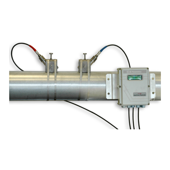
AquaTrans AT868
GE AquaTrans AT868 Manuals
Manuals and User Guides for GE AquaTrans AT868. We have
2
GE AquaTrans AT868 manuals available for free PDF download: User Manual, Abridged Manual
GE AquaTrans AT868 User Manual (158 pages)
Ultrasonic Flow Transmitter for Water (1- & 2-Channel)
Brand:
GE
| Category:
Transmitter
| Size: 1.89 MB
Table of Contents
Table of Contents
3
Introduction
10
Electronics Enclosure Location
11
Flowcell Location
11
Site Considerations
11
Transducer Location
11
Unpacking
11
Cable Lengths
12
Installing a Flowcell
12
Mounting the AT868 Electronics Enclosure
12
Transducer Cables
12
Making Electrical Connections
13
Preparing the Unit
13
Wiring the Line Power
13
Wiring Transducers
15
Wiring Std 0/4-20 Ma Analog Outputs
16
Wiring the Totalizer/Frequency Output
17
Wiring the Serial Port
18
Wiring an External Totalizer Reset Switch
21
Introduction
26
Accessing the ACTIV Submenu
27
Activating a Channel/Path - Chx-ACTIV
27
Accessing the Chx-SYSTM Submenu
28
Entering System Data for a Channel/Path - Chx-SYSTM
28
Selecting the Totalizer Units
28
Selecting the Volumetric Units
28
Selecting Mass Flow Units
29
Accessing the PIPE Submenu
30
Entering Transducer and Pipe Parameters - Chx-PIPE
30
Special Clamp-On Transducers
31
Special Transducers
31
Pipe Material
32
Path and Axial Length
33
Pipe Outside Diameter
33
Lining
34
Setting up a Tracking Window
34
Fluid Type
35
Reynolds Correction
35
KV Input Selection
36
Entering the Zero Cutoff Value - Chx-I/O
37
Number of Traverses and Transducer Spacing
37
Entering Setup Data - Chx-SETUP
38
Set Transducer Signal Settings - SIGNL
38
Setting Response Time - AVRG
41
Initializing Setup Parameters - INIT
42
Using Advanced Features - ADVAN
42
Entering Global System Data - GLOBL-SYSTM
47
Selecting the GLOBL-SYSTM Units
47
Selecting the System Units
47
Setting up the External Totalizer Reset Switch
48
Selecting Mass Flow Units
49
Selecting Error Handling - ERROR
50
Setting up the Inputs and Outputs - GLOBL-I/O
50
Setting up Analog and Totalizer/Frequency Outputs - OPTN
53
Configuring the Communications Port - GLOBL-COMM
58
Configuring the Output as a Totalizer or Frequency Output
59
Chapter 3: Displaying Data
62
Introduction
62
Adjusting LCD Contrast and Brightness
62
Setting up the Display
63
Resetting Totals
64
Resetting Totalizers Using the Internal Keypad
64
Resetting Totalizers Using Panaview
64
Resetting Totalizers Using the External Switch
64
Taking Measurements
65
Introduction
68
Calibrating and Testing Analog Outputs
68
Testing Output Linearity
70
Testing Totalizer/Frequency Outputs
71
Calibrating the Frequency Output
71
Calibrating the Totalizer Output
71
Chapter 5: Error Codes
74
Introduction
74
E0: no Error
74
E1: Low Signal
74
E2: Sound Speed Error
75
E3: Velocity Range
75
E4: Signal Quality
75
E5: Amplitude Error
75
E6: Cycle Skip, Accel
76
E7: Analog out Error
76
E8: Unassigned
76
E9: Totalizer Overflow
76
E10: Unassigned
76
E11: Unassigned
76
E12: Unassigned
76
E13: Volumetric Overflow
76
Chapter 6: Diagnostics
79
Introduction
79
Displaying Diagnostic Parameters
79
Using the Tracking Window
82
Diagnostic Record
83
Flowcell Problems
84
Fluid Problems
84
Pipe Problems
85
Transducer Problems
86
Wetted Transducer Problems
86
Clamp-On Transducer Problems
87
Introduction
90
Replacing the LCD Display/Keypad
91
Replacing the Fuse
92
Replacing the User Program
93
Chapter 8: Specifications
100
General Specifications
100
Electrical Specifications
101
Transducer Specifications
103
Pipe Size and Materials
104
Tilted Diameter Spoolpiece
105
Appendix A: Menu Maps
108
Appendix B: CE Mark Compliance
113
Introduction
114
EMC Compliance
114
LVD Compliance
115
Appendix C: Data Records
117
Site Data
118
Appendix D: Measuring P and L Dimensions
123
Measuring P and L
125
Appendix E: Service Record
127
Introduction
128
Data Entry
128
Diagnostic Parameters
130
Appendix F: Panaview™ for IDM-Compatible Meters (916-086B)
133
Introduction
133
IDM-Compatible Flowmeters
134
Starting up
134
Setting up the Communications Port
135
Adding an IDM-Compatible Meter
137
Editing Meter Properties
139
Setting the Meter Clock
141
Reading Transducer Signals
142
Plotting Transducer Signals
143
Saving Transducer Signals
143
Clearing Totalizers
143
Handling Site Files
144
Changing Meter Settings
147
Advertisement
GE AquaTrans AT868 Abridged Manual (67 pages)
Panametrics Liquid Flow Ultrasonic Transmitter
Brand:
GE
| Category:
Transmitter
| Size: 3.98 MB
Table of Contents
Table of Contents
5
Electronics Enclosure Location
9
Introduction
9
Site Considerations
9
Flowcell Location
10
Transducer Location
10
Cable Lengths
11
Installing a Flowcell
11
Transducer Cables
11
CE Mark Compliance
12
EMC Compliance
12
LVD Compliance
13
Making Electrical Connections
14
Preliminary Steps
14
Wiring the Line Power
15
Wiring Transducers
16
Wiring Standard 0/4-20 Ma Analog Outputs
17
Wiring the Totalizer/Frequency Output
18
Wiring the Serial Port
19
Chapter 2: Programming Site Data
22
Programming the AT868
22
Wiring an External Totalizer Reset Switch
22
Activating a Channel [Chx-ACTIV Menu]
27
Introduction
27
Accessing the ACTIV Submenu
28
Accessing the Chx-SYSTM Submenu
28
Entering System Data [Chx-SYSTM Menu]
28
Selecting Mass Flow Units
29
Selecting the Totalizer Units
29
Selecting the Volumetric Units
29
Accessing the PIPE Submenu
30
Entering Transducer and Pipe Parameters [Chx-PIPE Menu]
30
Special Clamp-On Transducers
31
Special Transducers
31
Pipe Material
32
Path and Axial Length
33
Pipe Outside Diameter
33
Lining
34
Setting up a Tracking Window
34
Fluid Type
35
Reynolds Correction
35
KV Input Selection
36
Number of Traverses and Transducer Spacing
36
Activating Mass Flow
37
Entering the Zero Cutoff Value [Chx-I/O Menu]
37
Entering Global System Data [GLOBL-SYSTM Menu]
38
Selecting the GLOBL-SYSTM Units
38
Selecting the System Units
38
Selecting Mass Flow Units
39
Setting up the External Totalizer Reset Switch
39
Accessing the Analog Outputs
40
Setting up the Analog Output Scale
40
Setting up the Outputs [GLOBL-I/O Menu]
40
Accessing the Totalizer/Frequency Outputs
41
Setting up a Frequency Output
42
Setting up a Totalizer Output
43
Configuring the Communications Port [GLOBL-COMM]
44
Taking Measurements
44
Adjusting LCD Contrast and Brightness
47
Introduction
47
Accessing the Display Submenu
48
Configuring the Display
48
Setting up the Display
48
Resetting the Totalizers
49
Resetting Totalizers Using an External Switch
49
Resetting Totalizers Using the Internal Keypad
49
Chapter 4: Calibration
51
Calibrating and Testing the Analog Outputs
52
Calibration
52
Introduction
52
Testing Linearity
53
Calibrating the Frequency Outputs
55
Calibrating the Totalizer Outputs
55
Calibrating the Totalizer/Frequency Outputs
55
Appendix A: Menu Maps
58
Appendix B: Measuring P and L Dimensions
63
Measuring P and L
63
Advertisement
Related Products
GE Carry-Cool ATM06
GE Carry Cool ATV05
GE ATS4000
GE ATS2000
GE ARITECH ATS7300
GE ATS125 Series
GE ATS1253
GE ATV05LZ
GE ATS1203N
GE AquaTrans AT600
GE Categories
Refrigerator
Ranges
Microwave Oven
Air Conditioner
Dishwasher
More GE Manuals
Login
Sign In
OR
Sign in with Facebook
Sign in with Google
Upload manual
Upload from disk
Upload from URL