Sign In
Upload
Manuals
Brands
GE Manuals
Surge Protector
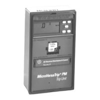
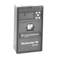
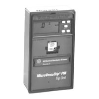
MicroVersaTrip PM
GE MicroVersaTrip PM Manuals
Manuals and User Guides for GE MicroVersaTrip PM. We have
6
GE MicroVersaTrip PM manuals available for free PDF download: User Manual, Installation Instructions Manual, Manual
GE MicroVersaTrip PM User Manual (52 pages)
Trip Units RMS9C Series; RMS9D Series;
Brand:
GE
| Category:
Surge Protector
| Size: 2.93 MB
Table of Contents
Table of Contents
4
Chapter 1. Introduction
11
1-1 Read this First
11
1-2 Product Structure
11
Front View of Microversatrip PM Trip Unit (Series RMS9C)
11
Front View of Microversatrip PM Trip Unit (Series RMS9D)
11
Rear View of Microversatrip PM Trip Unit (Series RMS9C)
12
Rear View of Microversatrip PM Trip Unit (Series RMS9D)
12
1-3 Trip Unit Functions
13
1-4 Trip Unit Catalog Numbers
13
Breaker Type Referred to by First Character of Trip Unit Catalog Number
13
Breaker Frame Size Maximum CT Referred to by Second Character of Trip Unit Catalog Number
14
Installed Breaker CT Size Referred to by Third and Fourth Characters of Trip Unit Catalog Number
14
Trip Unit Catalog Number Suffixes for Optional Functions
14
Microversatrip PM Trip Unit Suffixes for Communication, Metering, and Relaying
14
1-5 Rating Plugs
15
Rating Plug Catalog Numbers
15
1-6 Equipment Interfaces
16
Microversatrip Plus Trip Units
16
Neutral Current Sensors
16
Microversatrip PM Trip Units
16
POWER LEADER Communication Network
16
Voltage Inputs
16
Power Requirements
17
1-7 Trip Unit Information
17
Trip Unit Label Information
17
Function Keys
17
Labels on Front of Trip Unit
17
Battery Function
18
Function Key Placement on Face of Trip Unit
18
Liquid Crystal Display
19
Microversatrip Plus and Microversatrip PM Accuracies
19
Liquid Crystal Display Segments
19
Protective Relay and Metering Accuracies and Resolutions
19
Trip-Time Curves for Breaker Types Covered in this Guide
19
Chapter 2. Setup Mode
20
2-1 Overview
20
2-2 Operating Modes
20
2-3 Setup Mode Operation
20
Abbreviations Used in Setup Procedure Descriptions
20
Operation of FUNCTION Key, Showing Progression Among Trip Unit Operating Modes
21
Actions of Function Keys in Trip Unit Operating Modes
21
Trip Unit Setup Mode Programming Function Flow
22
Long-Time Pickup
26
Long-Time Delay
26
Short-Time Pickup
26
Trip Unit Display for Long-Time Pickup
26
Time-Current Curve Illustrating Long-Time Pickup
26
Trip Unit Display for Long-Time Delay
26
Time-Current Curve Illustrating Long-Time Delay
26
Lower-Limit Delays for Long-Time Delay Bands
26
Short-Time Delay
27
Trip Unit Display for Short-Time Pickup Coupled with Long-Time Pickup
27
Time-Current Curve Illustrating Short-Time Pickup
27
Trip Unit Display for Short-Time Delay
27
I 2 T out
27
Time-Current Curve for Short-Time Delay with
27
I 2 T in
27
Instantaneous Pickup
28
High-Range Instantaneous Overcurrent Protection
28
Ground-Fault Pickup
28
Trip Unit Display for Instantaneous Pickup
28
Instantaneous Overcurrent Protection Set Point
28
Trip Unit Display for Ground-Fault Pickup
28
Instantaneous Pickup Settings for Various Frame Sizes with and Without the Short-Time Function
28
Ground-Fault Pickup Settings, as a Function of Sensor Rating
28
Ground-Fault Delay
29
Voltage-Unbalance Relay Pickup
29
Time-Current Curve for Ground-Fault Pickup
29
Trip Unit Display for Ground-Fault Delay, Showing
29
I 2 T out
29
Time-Current Curve for Ground-Fault Delay with I 2 T out
29
Time-Current Curve for Ground-Fault Delay with
29
I 2 T in
29
Lower-Limit Delays for Ground-Fault Delay Bands
29
Voltage-Unbalance Relay Delay
30
Current-Unbalance Relay Pickup
30
Current-Unbalance Relay Delay
30
Undervoltage Relay Pickup
30
Undervoltage Relay Zero-Volt Trip Enable
30
Trip Unit Display for Voltage-Unbalance Relay Pickup
30
Trip Unit Display for Voltage-Unbalance Relay Delay
30
Trip Unit Display for Current-Unbalance Relay Pickup
30
Trip Unit Display for Current-Unbalance Relay Delay
30
Trip Unit Display for Undervoltage Relay Pickup
30
Undervoltage Relay Delay
31
Overvoltage Relay Pickup
31
Overvoltage Relay Delay
31
Power-Reversal Relay Pickup
31
Trip Unit Display for Undervoltage Relay Zero-Volt Trip Enabled
31
Trip Unit Display for Undervoltage Relay Delay
31
Trip Unit Display for Overvoltage Relay Pickup
31
Trip Unit Display for Overvoltage Relay Delay
31
Trip Unit Display for Power-Reversal Relay Pickup
31
Trip Unit Display for Power Direction Setup, Showing Line to Load
31
Trip Unit Display for Power-Reversal Relay Delay
32
Trip Unit Display for Rating Plug Current Set Point
32
Trip Unit Display for Potential Transformer Primary Voltage Set Point
32
Trip Unit Rating Plug Options
32
Trip Unit Display for Potential Transformer Connection Choice
33
Trip Unit Display for Power Demand Interval
33
Trip Unit Display for Setting Communication Address
33
Logic Diagram for Accessory Configurations
33
Power Demand Intervals
33
Accessory Configuration Switch on Rear of Trip Unit, Showing Factory Settings
34
Setting the Accessory Configuration Switches
34
Accessory Configuration Switch Settings, Including Factory Defaults
34
Trip Unit Metering Mode Function Flow
35
Overview
35
Trip Unit Display for Current Metering
37
Trip Unit Display for Line-To-Neutral Voltages
37
Trip Unit Display for Line-To-Line Voltages
37
Trip Unit Display for Aggregate Energy
37
Trip Unit Display for Aggregate Real Power
37
Current
37
Trip Unit Display for Aggregate Apparent Power
38
Trip Unit Display for Power Demand
38
Trip Unit Display for Frequency
38
Trip Unit Display for Normal Status
39
Chapter 3 . Metering Mode
39
Chapter 4 . Status Mode
39
Overview
39
Trip Unit Status Display for Long-Time Overcurrent Pickup
40
Typical Fault Display Following a Breaker Trip
40
Trip Unit Status Display for Long-Time Overcurrent Trip
40
Trip Unit Status Display for Short-Time Overcurrent Trip
40
Trip Unit Status Display for Instantaneous Overcurrent Trip
40
Trip Target and Fault Displays
40
Trip Unit Status Display for Ground-Fault Trip
41
Trip Unit Status Display for Protective-Relay Trip
41
Trip Unit Status Display for Undervoltage Release Trip
41
Trip Unit Display Targets for Protective Relays
41
Trip Unit Status Display for Long-Time Overcurrent Trip Counter
42
Clearing the Trip Operations Counters
42
Chapter 5 . Maintenance and Trouble-Shooting
43
Trip Unit Removal and Replacement
43
Removing the Interchangeable Rating Plug
44
Rating Plug Removal and Replacement
44
Trip Unit Battery Suppliers
49
Advertisement
GE MicroVersaTrip PM Installation Instructions Manual (20 pages)
Conversion Kits for Allis Chalmers, Siemens/Allis, and Siemens LA-800[F], and LA-1600[F] Gold Low-Voltage Power Circuit Breakers
Brand:
GE
| Category:
Industrial Equipment
| Size: 6.31 MB
Table of Contents
Table of Contents
2
Section 1. General Information
4
Section 2. before Installation
4
Section 3. Breaker Preparation
5
Primary Disconnects Removed from the Lower Studs, Showing the Original Current Sensors (LA-1600 Shown)
5
Original Flux Shifter and Trip Unit (Type LTS1 Shown) Mounting Locations (LA-1600 Shown)
5
Section 4. Installing the Conversion Kit
6
Installing and Adjusting the Flux Shifter Assembly
7
Installing the Flux Shifter Assembly
7
Flux Shifter Adjustment
7
Trip Screw Adjustment
8
Microswitch Linkage
8
Flux Shifter Test
8
Flux Shifter Assembly Installed, as Viewed from the Right Front of the Breaker (LA-800 Shown)
8
Installing the Trip Unit Wiring Harness
10
Adapter Bracket Locking Tabs
10
Installing the Trip Unit Mounting Plate
12
Flux Shifter Assembly
12
Mounting Plate and Support Bracket Mounted on the Breaker (Shown with Trip Unit Installed)
12
Installing the Current Sensors
13
LA-800 Current Sensors
13
LA-1600 Current Sensors
13
Installing the Current Sensors (LA-1600)
13
Installing the Communications Harness
14
Section 5. Installing the Trip Unit
14
Section 6. Four-Wire Ground Fault Option
15
Neutral Sensor Outline for LA-800 Breakers
15
Section 7 Testing and Trouble-Shooting
17
Testing
17
Trouble-Shooting
17
Nuisance Tripping on Ground Fault-Equipped Breakers
17
GE MicroVersaTrip PM User Manual (47 pages)
Trip Units for Type AKR Low-Voltage Power Circuit Breakers
Brand:
GE
| Category:
Circuit breakers
| Size: 3.28 MB
Advertisement
GE MicroVersaTrip PM User Manual (36 pages)
for Type AKR Low-Voltage Power Circuit Breakers Power Break Insulated-Case Circuit Breakers R-Frame Molded-Case Circuit Breakers
Brand:
GE
| Category:
Circuit breakers
| Size: 2.14 MB
GE MicroVersaTrip PM Installation Instructions Manual (28 pages)
Conversion Kits For I-T-E Type KB Low-Voltage Power Circuit Breakers
Brand:
GE
| Category:
Circuit breakers
| Size: 13.25 MB
Table of Contents
Optional Test
20
Important Note
20
Arc Chutes
23
Troubleshooting
26
GE MicroVersaTrip PM Manual (2 pages)
Rating Plugs, Power Break and AKR Circuit Breakers, MicroVersaTrip Plus & PM Conversion Kits
Brand:
GE
| Category:
Industrial Electrical
| Size: 0.41 MB
Advertisement
Related Products
GE MicroVersaTrip Plus
GE MicroVersaTrip Plus Conversion Kit
GE MicroVersaTrip Plus Series
GE MicroVersaTrip PM Series
GE MicroVersaTripPlus AK-50
GE MicroVersaTripPlus AKU-50
GE MicroVersaTripPlus AKS-50
GE MicroVersaTripPlus AKT-50
GE MicroVersaTripPlus AK-75
GE MicroVersaTripPlus AK-100
GE Categories
Refrigerator
Ranges
Microwave Oven
Air Conditioner
Dishwasher
More GE Manuals
Login
Sign In
OR
Sign in with Facebook
Sign in with Google
Upload manual
Upload from disk
Upload from URL