Sign In
Upload
Manuals
Brands
Hitachi Manuals
Storage
9900 Series
Hitachi 9900 Series Storage Array Manuals
Manuals and User Guides for Hitachi 9900 Series Storage Array. We have
3
Hitachi 9900 Series Storage Array manuals available for free PDF download: User And Reference Manual, Architecture Manual, User Manual
Hitachi 9900 Series User And Reference Manual (138 pages)
A subsystem
Brand:
Hitachi
| Category:
Network Hardware
| Size: 1.18 MB
Table of Contents
Thank You
5
Table of Contents
7
Chapter 1 Overview of the Lightning 9900™ Subsystem
15
Key Features of the Lightning 9900™ Subsystem
15
Continuous Data Availability
16
Connectivity
16
S/390 ® Compatibility and Functionality
17
Open-Systems Compatibility and Functionality
17
Hitachi Freedom NAS™ and Hitachi Freedom SAN
18
Program Products and Service Offerings
20
Table 1.1 Program Products and Service Offerings
20
Table 5.10 Table
21
Subsystem Scalability
22
Reliability, Availability, and Serviceability
23
Chapter 2 Subsystem Architecture and Components
25
Overview
25
Figure 2.1 Lightning 9900™ Histar Network (HSN) Architecture
25
Figure 2.2 9960 Subsystem Frames
27
Figure 2.3 9910 Subsystem Frame
27
Components of the Controller Frame
28
Storage Clusters
28
Nonvolatile Shared Memory
29
Nonvolatile Duplex Cache
29
Multiple Data and Control Paths
30
Redundant Power Supplies
30
Client-Host Interface Processors (Chips) and Channels
30
Table 2.1 CHIP and Channel Specifications
31
Channels
32
Array Control Processors (Acps)
33
Figure 2.4 Conceptual ACP Array Domain
33
Table 2.2 ACP Specifications
34
Array Frame
35
Table 2.3 Disk Drive Specifications
36
Disk Array Groups
37
Figure 2.5 Sample RAID-1 Layout
37
Figure 2.6 Sample RAID-5 Layout (Data Plus Parity Stripe)
38
Sequential Data Striping
38
Intermix Configurations
39
RAID-1 & RAID-5 Intermix
39
Hard Disk Drive Intermix
39
Figure 2.7 Sample Hard Disk Drive Intermix
39
Device Emulation Intermix
40
Figure 2.8 Sample Device Emulation Intermix
40
Service Processor (SVP)
41
Remote Console PC
41
Chapter 3 Functional and Operational Characteristics
43
New 9900 Features and Capabilities
43
I/O Operations
43
Cache Management
44
Algorithms for Cache Control
44
Write Pending Rate
44
Control Unit (CU) Images, Lvis, and Lus
45
CU Images
45
Logical Volume Image (Lvis)
45
Logical Unit (LU) Type
45
Figure 3.1 Fibre-Channel Device Addressing
45
Table 3.1 Capacities of Standard LU Types
45
System Option Modes
46
Table 3.2 Common System Option Modes
46
Table 3.3 System Option Modes for Mainframe Connectivity
46
Table 3.4 System Option Modes for Open-System Connectivity
47
Table 3.5 System Option Modes for Shadowimage - S/390 ® and Shadowimage
48
Table 3.6 System Option Modes for Truecopy
48
Table 3.7 System Option Modes for HXRC
50
Table 3.8 System Option Modes for Concurrent Copy (CC)
50
Open Systems Features and Functions
51
Failover and SNMP Support
51
Share-Everything Architecture
51
SCSI Extended Copy Command Support
51
Data Management Functions
52
Table 3.9 Data Management Functions for Open-System Users
52
Table 3.10 Data Management Functions for S/390 ® Users
53
Hitachi Truecopy
54
Hitachi Truecopy (TC)
54
Hitachi Shadowimage (SI)
55
Hitachi Shadowimage - S/390 ® (SI390)
55
Command Control Interface (CCI)
56
Extended Copy Manager (ECM)
56
Hitachi Extended Remote Copy (HXRC)
57
Data Migration
58
Hitachi Nanocopy
58
Hitachi Multiplatform Backup/Restore (HMBR)
59
Hitachi Rapidxchange (HRX)
59
3.7.14 Hicommand
60
HARBOR ® File Transfer
60
HARBOR ® File-Level Backup/Restore
60
3.7.15 LUN Manager
61
3.7.17 Virtual LVI/LUN
61
LU Size Expansion (LUSE)
61
3.7.18 Flashaccess
62
3.7.19 Cache Manager
62
Hitachi Santinel
63
Hitachi Santinel - S/390
63
3.7.25 LDEV Guard
64
Dynamic Link Manager™ (DLM)
64
Hitachi Parallel Access Volume (HPAV)
64
Prioritized Port and WWN Control (PPC)
64
3.7.26 Hitachi Cruisecontrol
65
3.7.27 Hitachi Graph-Track
66
Chapter 4 Configuring and Using the 9900 Subsystem
67
S/390 ® Configuration
67
Subsystem Ids (Ssids)
67
Table 4.1 SSID Requirements
67
S/390 ® Hardware Definition
68
Hardware Definition Using IOCP (MVS, VM, or VSE)
68
Figure 4.1 IOCP Definition for FICON™ Channels
69
Figure 4.2 IOCP Definition for 1024 Lvis (9900 Connected to Host CPU(S) Via ESCD)
70
Figure 4.3 IOCP Definition for 1024 Lvis (9900 Directly Connected to CPU)
71
Table 4.2 Correspondence between Physical Paths and Channel Interface Ids (Cl 1)
72
Table 4.3 Correspondence between Physical Paths and Channel Interface Ids (Cl 2)
72
Hardware Definition Using HCD (MVS/ESA)
73
Table 4.4 HCD Definition for 64 Lvis
73
Table 4.5 HCD Definition for 256 Lvis
73
Figure 4.4 Master MENU (Step 1)
75
Figure 4.5 Basic HCD Panel (Step 2)
76
Figure 4.6 Define, Modify, or View Configuration Data (Step 3)
76
Figure 4.7 Control Unit List Panel (Step 4)
77
Figure 4.8 Add Control Unit Panel (Step 5)
77
Figure 4.9 Selecting the Operating System (Step 6)
78
Figure 4.10 Control Unit Chpid, CUADD, and Device Address Range Addressing (Step 7)
78
Figure 4.11 Select Processor / Control Unit Panel (Step 8)
79
Figure 4.12 Control Unit List (Step 9)
79
Figure 4.13 I/O Device List Panel (Step 10)
80
Figure 4.14 Add Device Panel (Step 11)
80
Figure 4.15 Device / Processor Definition Panel - Selecting the Processor ID (Step 12)
81
Figure 4.16 Define Device / Processor Panel (Step 13)
81
Figure 4.17 Device / Processor Definition Panel (Step 14)
82
Figure 4.18 Define Device to Operating System Configuration (Step 15)
82
Figure 4.19 Define Device Parameters / Features Panel (Step 16)
83
Figure 4.20 Update Serial Number, Description and VOLSER Panel (Step 18)
83
Defining the 9900 to VM/ESA ® Systems
84
Defining the 9900 to TPF
84
S/390 ® Operations
85
Initializing the Lvis
85
Device Operations: ICKDSF
85
Figure 4.21 LVI Initialization for MVS: ICKDSF JCL
85
Table 4.6 ICKDSF Commands for 9900 Contrasted to RAMAC
86
MVS Cache Operations
87
Figure 4.22 Displaying Cache Statistics Using MVS DFSMS
87
Figure 4.23 IDCAMS LISTDATA COUNTS (JCL Example)
87
VM/ESA ® Cache Operations
89
VSE/ESA Cache Operations
89
Open-Systems Configuration
90
Table 4.7 9900 Open-System Platforms and Configuration Guides
90
Configuring the Fibre-Channel Ports
91
Figure 4.24 Fibre Port-To-LUN Addressing
91
LU Size Expansion (LUSE) Devices
91
Virtual LVI/LUN Devices
91
Open Systems Operations
92
Command Tag Queuing
92
Host/Application Failover Support
92
Path Failover Support
93
Figure 4.25 Alternate Pathing
93
Remote SIM (R-SIM) Reporting
94
SNMP Remote Subsystem Management
94
NAS and SAN Operations
94
Chapter 5 Planning for Installation and Operation
95
User Responsibilities
95
Electrical Specifications and Requirements for Three-Phase Subsystems
96
Internal Cable Diagram
96
Figure 5.1 Diagram of Power Plugs for Three-Phase 9960 Disk Array Unit (Europe)
96
Power Plugs
97
Figure 5.2 Diagram of Power Plugs for Three-Phase 9960 Disk Array Unit (USA)
97
Figure 5.3 Diagram of Power Plugs for Three-Phase 9960 Disk Array Unit (Europe)
97
Features
98
Current Rating, Power Plug, Receptacle, and Connector for Three-Phase (60 Hz Only)
98
Table 5.1 9960 Three-Phase Features
98
Table 5.2 Current Rating, Power Plug, Receptacle, and Connector for 3-Phase 9960
98
Input Voltage Tolerances
99
Table 5.3 Input Voltage Specifications for Three-Phase Power
99
Electrical Specifications and Requirements for Single-Phase Subsystems
100
Internal Cable Diagram
100
Figure 5.4 Internal Cable Diagram of a Single-Phase 9960 Subsystem
100
Figure 5.5 Internal Cable Diagram of a Single-Phase 9910 Subsystem
101
Power Plugs
102
Figure 5.6 Power Plugs for Single-Phase 9960 Controller (USA)
102
Figure 5.7 Power Plugs for Single-Phase 9910 Subsystem (USA)
102
Figure 5.8 Power Plugs for a Single-Phase 9960 Controller (Europe)
103
Figure 5.9 Power Plugs for a Single-Phase 9910 Subsystem (Europe)
103
Figure 5.10 Power Plugs for Single-Phase 9960 Disk Array Unit (USA)
104
Features
105
Current Rating, Power Plug, Receptacle, and Connector for Single-Phase (60 Hz Only)
105
Table 5.4 9900 Single-Phase Features
105
Table 5.5 Current Rating, Power Plug, Receptacle, and Connector for 1-Phase 9900
105
Input Voltage Tolerances
106
Table 5.6 Input Voltage Specifications for Single-Phase Power
106
Dimensions and Weight
107
Table 5.7 9900 Physical Specifications
108
Table 5.8 9960 Frame and Component Weights
109
Table 5.9 9960 & 9910 Subsystem Weights
109
Floor Loading and Cable Routing Requirements
110
Service Clearance Requirements
110
Minimum Subsystem Disk Configuration
115
Floor Load Rating
119
Table 5.10 Floor Load Rating for 9910 Subsystem
119
Table 5.11 Floor Load Rating for 9960 Controller with 1 Disk Array
119
Table 5.12 Floor Load Rating for 9960 Controller with 4 Disk Arrays
121
Table 5.13 Floor Load Rating for 9960 Controller with Maximum Configuration
122
Cable Requirements
123
Table 5.14 Cable Requirements
123
Channel Specifications and Requirements
124
Table 5.15 ESCON ® and FICON™ Port Information
124
Table 5.16 Fibre-Channel Port Information
124
Environmental Specifications and Requirements
125
Temperature and Humidity Requirements
125
Power Consumption and Heat Output Specifications
125
Table 5.17 Temperature and Humidity Requirements
125
Table 5.18 9910/9960 Component Power and Heat Output Specifications
126
Table 5.19 9900 Subsystem Power and Heat Output Specifications
126
Loudness
127
Air Flow Requirements
127
Table 5.20 Internal Air Flow
127
Vibration and Shock Tolerances
128
Table 5.21 Vibration and Shock Tolerances
128
Chapter 6 Troubleshooting
129
Service Information Messages (Sims)
130
Table 6.1 Troubleshooting
130
Figure 6.1 Typical 9900 SIM Showing Reference Code and SIM Type
130
Calling the Hitachi Data Systems Support Center
131
Appendix A Unit Conversions
133
Table A.1 Unit Conversions for Standard (U.S.) and Metric Measures
133
Acronyms and Abbreviations
135
Advertisement
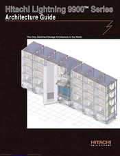
Hitachi 9900 Series Architecture Manual (80 pages)
Hitachi Lightening System Architecture Guide
Brand:
Hitachi
| Category:
Storage
| Size: 1.29 MB
Table of Contents
Table of Contents
4
Table of Figures
8
Chapter 1 - Introduction
10
The Only Switched-Fabric Storage Architecture in the World
10
Lightning 9900 Series Product Offerings
10
An Overview of the Hitachi Lightning 9900 Series Architecture
11
Figure 1 the 9960 Provides for Exploding Growth and Data Consolidation While the 9910 Provides for Managed Growth and Open System Exploitation
11
Table 1 Comparison of the Lightning 9900 Series Models
11
Figure 2 the Hitachi Lightning 9960 Series' Hi-Star Internal Switched-Fabric Architecture
12
Comparison to the Shared Bus Architecture of the Hitachi Freedom Storage 7700E
13
The Lightning 9900 Has an Advanced Availability Profile Compared to Competitive Products
13
Figure 3 System Block Diagram of the 7700E's Shared Bus Architecture
13
Other Information Sources Available from Hitachi Data Systems
14
Chapter 2 - the Lightning 9900 Series Packaging
16
Model 9960 Packaging
16
Model 9960 Control Frame
16
Figure 4 a 9960 Control Frame and Its Major Components
16
Model 9960 Array Frames
17
Figure 5 a 9960 Array Frame with Its Major Components
17
Model 9910 Packaging
18
Figure 6 a Power Supply Module of a Lightning 9900 Series System
18
The System Monitoring Network of the Lightning 9900 Series
19
Figure 7 a 9910 Single-Cabinet Storage Subsystem
19
Chapter 3 - Front-End Design of the Hitachi Lightning 9900 Series
20
Chips Support Fibre Channel Host and ESCON Host Connectivity and Scalability
20
Figure 8 Fibre Channel and ESCON or FICON Adapter Boards Connect to Open Systems and Mainframe Computers
20
About the Fibre Channel Interface Boards
21
Figure 9 a Fibre Channel Host Adapter Board and Its Major Hardware Components
21
Figure 10 an ESCON Host Adaper Board and Its Major Hardware Components
22
Bandwidth of Supported Host Interfaces
23
Number of Host Interfaces Supported
23
Types of Hosts Supported by Direct Fibre Channel Host Attachment by the Lightning 9900 Series
23
Figure 11 a 9960 System Connected to Mainframes and Open Systems Hosts
23
Table 2 Bandwidth of Supported Interfaces of the Lightning 9900 Series
23
Chapter 4 - Hi-Star Architecture - an Internal Switched Hierarchial Star Network
24
The Internal Hi-Star Architecture
24
The Cache Hierarchical Star Network
24
Figure 12 the Cache Hierarchical Star Network (C-HSN) Provides Fully Redundant Switched Access to Cache from All Channel Adapters
24
The Cache Switch Provides Non-Blocking Switched Access to Cache
25
The Path Bandwidth between the CSW and Chips or Acps Is 6.4Gb/Sec
25
The Path Bandwidth between the CSW and the Cache Adapter (Cas) Is 3.2Gb/Sec
25
Advantages of a Switched Architecture Compared to a Shared Bus Architecture
25
Figure 13 the CSW and Carbs Provide Non-Blocking Channel Access to All Cache
25
Figure 14 a Shared-Bus Architecture Is Limited to Two Simultaneous I/O Operations
26
Figure 15 the Lightning 9900 Series Hi-Star Architecture Allows for 16 Parallel I/Os to Cache through Four Interconnecting Cache Switches
26
The 9960 Provides 32GB of Fully Addressable Cache
27
Advanced Cache Algorithms of the Lightning 9900 Series
27
Hitachi Flashaccess Allows Datasets to be Permanently Placed in Cache
27
Read-Ahead for High-Performance Sequential Reads
27
The Control Memory Hierarchical Star Network
27
Figure 16 Separate Redundant Control Memory Handles the Exchange of Control Information between Processors and Cache Memory about the Status, Location, and Configuration of Data
28
Chapter 5 - High Performance Back-End Design
30
High-Performance Back-End Design
30
New Fibre Channel Disk Drives
30
Figure 17 Functional Diagram of a Lightning 9900 Series ACP Pair
30
Maximum Configuration of Acps and Disks
31
The Importance of Command Tag Queuing (CTQ)
31
Figure 18 Functional Diagram of an Array Group with FC-AL Disks
31
Figure 19 Diagram of Four ACP Pairs and 32 FC-AL Back-End Disks
31
Chapter 6 - Capacities and RAID Architecture
32
Storage Capacity of the Lightning 9900 Series
32
Advantages of the Lightning 9900 Series RAID Hardware
32
Raid-1
32
RAID-5 Distributed Parity
32
RAID Rebuild Capability
32
Table 3 System Capacities and Number of Disk Drives for Various Configurations
32
High-Density Disk Drive Assemblies (Hdds)
33
Figure 20 the Lightning 9900 Series Systems Are Available with RAID-1+ and RAID-5 Arrays
33
Chapter 7 - Hitachi High-Availability Software Improves Application Service Levels
34
An Overview of High Availability (HA) Computing Software
34
Software Products Contribute to High-Availability Computing
34
The Lightning 9900 Has an Advanced Availability Profile Compared to Competitive Products
34
Open Systems High-Availability Middleware Support
35
Figure 21 the Lightning 9900 Offers a Far more Complete Range of Availability Protection than
35
Alternate Pathing Middleware Switches the I/O Load in the Event of Path Failure
36
Hitachi Dynamic Link Manager Provides Path Failover and Load Balancing
36
Host Failover
36
Parallel Database Clustering
37
Standard Hot-Swap and Redundant Power Supplies
37
Figure 22 Hitachi Dynamic Link Manager Automatically Provides Path Failover and Load Balancing for Open Systems
37
Standard Redundant Fans for Cooling
38
Unmatched Competitive Advantage in RAID Choices
38
Chapter 8 - Performance Considerations
40
Truly Scalable Performance
40
The Advantages of the Lightning 9900 Series Hi-Star Architecture over a Shared Bus Architecture
40
Figure 23 Test Results Show the Advantages of the 9960 Histar Architecture When Compared to a Shared Bus Architecture
40
Internal Switching Overcomes the Limitations of Shared Bus Architectures
41
Test Results
41
Chapter 9 - the Lightning 9900 Series Software Solutions Are the Best in the World
42
Table 4 Summary of Hitachi Freedom Storage Software Products and the Business Objectives They Serve
42
Increased IT Service Levels in Availability and Performance through Business Continuity Planning (BCP) Software and Services
43
Figure 24 Hitachi Data Systems Offers a Broad Range of Remote Copy, Data Duplication, and Data Migration Software Solutions
43
Remote Copy, Data Duplication, Data Migration Defined
44
Remote Copy
44
Pit Copy
44
Data Migration
44
Business Goals Served by Hitachi Copy Software
45
Table 5 Hitachi Copy Products Provide Remote Copy, Data Duplication and Data Migration
45
Chapter 10 - Centralized and Open Systems Management Software Simplifies IT Operations
46
A Powerful and Open Systems Management Philosophy
46
Hicommand Allows Systems Management of Hitachi Storage and Software through the Enterprise's Vendor of Choice
46
Figure 25 Hicommand Allows Management of Virtually All Hitachi Hardware and Software from the Customer's Platform of Choice
47
The Components of Hicommand
48
Overview of How the Systems Management Software Supports Business Objectives
48
Hitachi Resource Manager 9000
49
Service Level Management
49
Deployment Management
49
Compliance Management
49
SNMP Support Ensures Compliance with All Major Systems Management Platforms
49
Hitachi Graph-Track Takes the Guess-Work out of Performance Management
49
Hitachi LUN Manager Simplifies Configuration Management and Reduces Staffing Costs
50
Figure 26 the GUI Interface on Hitachi Graph-Track Simplifies Performance Management
50
Hitachi Virtual Logical Volume Image Manager Allows very Large to very Small Virtual Volume Configuration
51
Hitachi Flashaccess Allows Data to be "Locked and Unlocked" in Cache On-The-Fly
51
Hitachi Cruisecontrol
51
Storage Maximizer
52
Hitachi Santinel
52
Transaction Processing Facility/Multi-Path Lock Facility (TPF/MPLF)
52
Chapter 11 - Professional Services and Support
54
Hitachi Data Systems Is Consistently Ranked Number One in the Industry
54
Professional Services Overview
54
Cost of Risk Analysis Methodology (CORA)
54
Data Protection Services
54
Data Protection Services Lab
55
Remote Copy Assessment and Implementation Service
55
Hitachi Nanocopy Implementation Service
55
Continuous Availability Service
56
On-Line Data Migration Service
56
SAN Services
56
Hitachi Data Systems Interoperability Laboratory Service
57
Enterprise Storage and Availability Management Services
57
Software Portfolio Review and Analysis Service
57
Appendix A - System Configurations for the Performance Experiment
58
Glossary of Terms
60
Hitachi 9900 Series User Manual (64 pages)
LUN Expansion and Virtual LVI/LUN
Brand:
Hitachi
| Category:
Storage
| Size: 0.76 MB
Table of Contents
Table of Contents
9
Chapter 1 Overview of LUN Expansion and Virtual LVI/LUN
13
Overview of LUSE Operations
13
LUSE Specifications
14
Table 1.1
14
Table 1.2 VLL LUSE Specifications
14
Figure 1.1 LUSE Configuration
15
Overview of Virtual LVI/LUN
16
Virtual LVI/LUN Parameters
16
Figure 1.2 Illustration of Virtual LVI/LUN Operations
16
Figure 1.3 Volume Configuration
18
Table 1.3 Virtual LVI/LUN Specifications
19
Table 1.4 Minimum and Maximum Virtual LUN Volume Capacities (Open Systems)
20
Control Cylinders/Control Area for each LVI/LU Type
20
Table 1.5
20
Virtual LVI/LUN Size Calculation
21
SSID Requirements)
22
SSID Requirements
22
Table 1.6 SSID Requirements
22
Chapter 2 Preparing to Use LUN Expansion or Virtual LVI/LUN
23
Set up the 9900V Subsystem and Remote Console PC(S)
23
Launch LUN Expansion or Virtual LVI/LUN
23
Figure 2.1 Remote Console Main Panel, Information Tab
24
Changing to Modify Mode
25
Figure 2.2 View Mode
26
Figure 2.3 Mode Changing Confirmation Message
26
Figure 2.4 Modify Mode
26
Chapter 3 LUN Expansion (LUSE) Operations
27
The LUSE/VLL Panel, LUSE Tab Components
27
Figure 3.1 LUSE/VLL Main Panel, LUSE Tab
27
Figure 3.2 LDEV Information Outline Detail (from the LUSE/VLL Panel, LUSE Tab)
28
Figure 3.3 LDEV Detail Table (from the LUSE/VLL Panel, LUSE Tab)
29
Figure 3.4 LDEV Operation Detail (from the LUSE/VLL Panel, LUSE Tab)
30
LUSE Operations
31
Creating a LUSE Volume
31
Creating a LUSE Volume from the LDEV Operation Detail
31
Figure 3.5 Set LUSE Confirmation Panel
32
Figure 3.6 Apply Confirmation Message
32
Figure 3.7 Cancel Confirmation Message
32
Creating a LUSE Volume from the LDEV Table
33
Figure 3.8 Selecting Free Ldevs for LUSE Volume
34
Figure 3.9 Set LUSE Volume Pop-Up Menu
34
Releasing a LUSE Volume
35
Figure 3.10 Selecting LUSE Volume(S) to be Released
36
Figure 3.11 Release LUSE Volume Pop-Up Menu
36
Changing LUSE Capacities
37
Figure 3.12 Release LUSE Confirmation Panel
37
Chapter 4 Virtual LVI/LUN (VLL) Operations
39
The Virtual LVI/LUN Panels
39
LUSE/VLL Panel, VLL Tab
39
Figure 4.1 LUSE/VLL Panel, VLL Tab
39
Figure 4.2 Parity Group - LDEV Outline (from the LUSE/VLL Panel, VLL Tab)
40
Figure 4.3 LDEV Information Table (from the LUSE/VLL Panel, VLL Tab)
41
Table 4.1 Emulation Groups
41
Set SSID Panel
42
Figure 4.4 Set SSID Panel
42
Virtual LVI/LUN Operations
44
Converting Logical Volumes to Space
44
Figure 4.5 Volume to Space Pop-Up Menu
46
Figure 4.6 Volume to Space Confirmation Panel
46
Creating VLL Volumes
47
Table
48
Figure 4.7 Install CV Pop-Up Menu
49
Figure 4.8 Install CV Panel (1)
49
Figure 4.9 Clear Pop-Up Menu
49
Figure 4.10 Install CV Panel (2)
50
Figure 4.11 Set SSID Panel (Installing VLL Volumes)
50
Figure 4.12 Install CV Confirmation Panel
51
Deleting a VLL Volume
52
Initializing a Virtual LVI/LUN Volume
52
Figure 4.13 Volume Initialize Pop-Up Menu
54
Figure 4.14 Volume Initialize Panel
55
Figure 4.15 Clear Pop-Up Menu
55
Figure 4.16 Set SSID Panel (Volume Initialize)
56
Figure 4.17 Volume Initialize Confirmation Panel
56
Chapter 5 Troubleshooting
57
Troubleshooting
57
General Error Conditions
58
Table 5.1 General Error Conditions
58
Calling the Hitachi Data Systems Technical Support Center
59
Glossary, Acronyms, and Abbreviations
61
Advertisement
Advertisement
Related Products
Hitachi 9960
Hitachi 93-04-01
Hitachi 937913Z - Wrench Spanner For G18MR
Hitachi 937984Z - Wheel Guard For G23MR
Hitachi WR9DMR - Power Tools 9.6V 3/8" Impact Wrench
Hitachi SelecSet 900 Series
Hitachi CJ 90VAST
Hitachi 915/4160
Hitachi 951/7460
Hitachi 944458
Hitachi Categories
Projector
Air Conditioner
Drill
Power Tool
TV
More Hitachi Manuals
Login
Sign In
OR
Sign in with Facebook
Sign in with Google
Upload manual
Upload from disk
Upload from URL