Sign In
Upload
Manuals
Brands
Honeywell Manuals
Desktop
788011
Honeywell 788011 Manuals
Manuals and User Guides for Honeywell 788011. We have
2
Honeywell 788011 manuals available for free PDF download: Operation And Installation Instruction, Operation And Installation Instructions Manual
Honeywell 788011 Operation And Installation Instruction (116 pages)
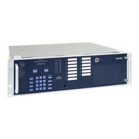
Extinguishing Control Computer
Brand:
Honeywell
| Category:
Control Unit
| Size: 2.04 MB
Table of Contents
Deutsch
3
Bedienungsanleitung
1
Table of Contents
3
1 Allgemein
4
2 Anzeige und Bedienfeld
5
Gruppenanzeigen
6
Zustandsanzeige der Gruppen
6
Zustandsanzeige der Ausgänge
7
Betriebsanzeigen
8
Störungsanzeigen
10
Die Tastaturfunktionen
12
Ein-/Ausschalten von Gruppen
13
Ein-/Ausschalten von Relaisausgängen
14
Testbetrieb
15
Revisionsbetrieb
16
Zentrale Rückstellen
17
Lampentest
17
3 Steuerungsanzeige und Alarmzähler (Option)
18
4 Installationsanleitung
19
Installationsanleitung
21
Installationshinweise
21
Normen und Richtlinien
22
Verantwortung des Errichters
23
Mechanischer Aufbau
24
Energieversorgung
25
Notstromversorgung
25
Kabeleinführungen / Anschluss
26
Netzanschluss und Erdung
27
Baugruppen
29
Prozessorkarte
29
Abbruch des Löschvorganges zu Testzwecke durch den Errichter
29
Gruppenkarte
30
Meldergruppen Nr.1 bis Nr. 8
32
Betriebsarten der Meldergruppen
33
Technische Gruppen
34
Steuereingang MG14 und MG15
36
Netzteil- und Relaiskarte
37
Relaisausgänge
39
Betriebsart der Relais 1 bis 8
41
Ansteuerbedingung der Relais (AE)
42
Notbetriebsfunktion
45
Standardschnittstelle - Löschen
46
Steuerungsanzeige und Alarmzähler (Art.-Nr. 788016)
47
Ablaufdiagramm
48
Zeitlicher Ablauf bei Alarm (als Löschmittelsteuerung)
48
Zeitlicher Ablauf bei Alarm (als Aquasafe)
51
Technische Daten
53
Anschaltungen
54
Brandmeldesystem 8000 / Iq8Control / Essernet
54
Esserbus
54
LMST 8010 als Esserbus ® -Teilnehmer
54
Sondermelder
55
Mehrbereichssteuerung
56
Operation Instruction
59
English
61
General
62
Display and Control Panel
63
Single Zone Display
64
Status Display of the Zones
64
Status Display of the Outputs
65
Operating Displays
66
Trouble Displays
68
Keypad Functions
70
Connect / Disconnect Zones
71
Connect / Disconnect Relay Outputs
72
Test Mode
73
Revision Mode
74
Resetting the Panel 8010
75
Lamp Test
75
Control Indicator and Alarm Counter (Option)
76
Installation Instruction
77
Installation
79
Installation Information
79
Standards and Guidelines
80
Mechanical Configuration
81
Power Supply
82
Emergency Power Supply
82
Mounting the Cabinet / Installation
83
Mains Connection and Protective Earth (PE)
84
Devices
86
Processor Board
86
Stop Extinguishing Procedure for Test Purposes by the Operator
86
Zone Board
87
Detector Zones No.1 to No. 8
89
Operating Modes of the Detector Zones
90
Technical Zones
91
Control Input MG14 and MG15
93
Power Supply Unit Board and Relay Board
94
Relay Outputs
96
Operating Mode of the Relays No. 1 to 8
98
Activation Condition for the Relays
99
CPU-Failure Mode
102
Standardized Interface - Extinguishing
103
Control Indicator and Alarm Counter (Part No. 788016)
104
Sequence Diagram
105
Time Sequence on Alarm (for Extinguishing System)
105
Time Sequence on Alarm (for Aquasafe)
108
Specifications
110
Connections
111
Essernet
111
Fire Alarm System 8000 / Iq8Control
111
Extinguishing Control Computer 8010 as an Esserbus
111
Device
111
Third-Party Detectors
112
Multisector-Control
113
Advertisement
Honeywell 788011 Operation And Installation Instructions Manual (78 pages)
Extinguishing Control Computer

Brand:
Honeywell
| Category:
Desktop
| Size: 1.64 MB
Table of Contents
Novar Gmbh, Dieselstrasse 2, D-41469 Neuss 06 0786 - Cpd - 2022
3
Operation Instruction
1
Table of Contents
3
1 General
4
Accessories / Options
4
2 Display and Control Panel
5
LED Indicator for Zones and Outputs
6
Status Display of the Zones
6
Status Display of the Outputs
7
Operating Displays
8
Trouble Displays
10
Keypad Functions
12
Connect / Disconnect Zones
13
Connect / Disconnect Relay Outputs
14
Test Mode
15
Revision Mode
16
Resetting the Panel
17
Lamp Test
17
3 Control Indicator and Alarm Counter
18
4 Installation Instruction
19
Installation Instruction
20
Installation
21
Installers Responsibility
21
Standards and Guidelines
22
Installation Information
24
Mechanical Configuration
26
Operating- and Connecting Devices
26
19-Inch Rack Mounting
27
Mains Connection and Protective Earth (PE)
30
Emergency Power Supply
32
Position and Operation of the Devices
34
Processor Board
35
Stop Extinguishing Procedure for Test Purposes by the Operator
35
Zone Board - Series 2
36
Detector Zones 1 to 8 (Zone Card Series 2)
38
Zone Board - Series 3
39
Terminal Assignment of the Zones
43
Zone-Terminal Card (Type Phoenix / Weco)
44
Zone-Terminal Card (Type Weidmüller)
45
Detector Zones 1 to 8
46
Operating Modes of the Detector Zones
47
Technical Zones
48
Control Input MG14 and MG15
50
Power Supply Unit Board and Relay Board
51
Terminal Assignment of the Relays
53
Relay Outputs 1 to 8
57
Relay Outputs, 10 and 11
59
Relay Outputs 12 and 13 (Power Supply Relay)
60
Standardized Interface - Extinguishing
61
Activation Condition for the Relays (AE)
62
Status Functions
63
CPU-Failure Mode
65
Analog Loop Connection
66
Sequence Diagram
67
Time Sequence on Alarm (for Extinguishing System)
67
Time Sequence on Alarm (for Aquasafe)
70
Specification
72
Connections
73
Operation of the Extinguishing Control Computer in the Fire Alarm System 8000 / Iq8Control
73
Extinguishing Control Computer 8010 Connected to the Analog Loop
73
Third-Party Detectors Via Reset Module to LMST 8010 - 19-Inch Series 2
74
Third-Party Detectors Via Esserbus
75
Multisector-Control
76
Advertisement
Related Products
Honeywell 788010
Honeywell 788012
Honeywell 788013
Honeywell 788024
Honeywell 788025
Honeywell 788014
Honeywell 788015
Honeywell Dolphin 7800
Honeywell 7800 SERIES EC7895A
Honeywell AlarmNet 7845GSMCN
Honeywell Categories
Thermostat
Controller
Control Unit
Security Camera
Accessories
More Honeywell Manuals
Login
Sign In
OR
Sign in with Facebook
Sign in with Google
Upload manual
Upload from disk
Upload from URL