Sign In
Upload
Manuals
Brands
Honeywell Manuals
Marine Radio
89000007-000001
User Manuals: Honeywell 89000007-000001 Marine Radio
Manuals and User Guides for Honeywell 89000007-000001 Marine Radio. We have
1
Honeywell 89000007-000001 Marine Radio manual available for free PDF download: Installation Manual
Honeywell 89000007-000001 Installation Manual (74 pages)
Brand:
Honeywell
| Category:
Marine Radio
| Size: 0.5 MB
Table of Contents
Table of Contents
13
Title Page
14
Introduction
19
How to Use this Manual
19
General
19
Observance of Manual Instructions
19
Symbols
19
Figure INTRO-1. Symbols
19
Units of Measure
20
Standard Practices Manual
20
Electrostatic Discharge
20
Bendixking Technical Publications Support
20
Honeywell Aerospace Online Technical Publications Website
20
Bendixking Customer Support
20
References
20
Honeywell/Vendor Publications
20
Other Publications
21
Acronyms and Abbreviations
22
General
22
Software History
24
Software Data
24
Section 1 General Information
25
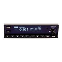
KT 74 Description
25
Interfaces
25
Table 1-1. Interface Services
25
Regulatory
26
Table 1-2. Regulatory Data
26
Approved Deviations
27
Physical Specifications (in Tray)
27
Table 1-3. Physical Specifications
27
Installation Approval
28
TSO Failure Condition Classification
28
Non-TSO Functions
28
KT 74 Mode S Transponder Items
28
Table 1-4. Included Transponder Items
28
Installation Kit
29
Documentation Kit
29
Required Items
29
Table 1-5. Installation Kit
29
Table 1-6. Documentation Kit
29
Normal Operations Overview
30
Display
30
Figure 1-1. KT 74 Display
30
Mode Selector Knob
31
Push Buttons
31
Squawk Code Entry
31
Table 1-7. Push Button Functions
31
Flight Timer
32
Stopwatch
32
Flight ID Entry
32
Altitude Monitor
32
ADS-B Monitor
33
Warning Messages
33
Fault Annunciation
33
Low Temperature Operation
33
Limited Warranty
34
ADS-B Compliance
35
ADS-B Parameters Supported
35
Table 1-8. ADS-B Parameters
35
FAA 91.227 Compliance
37
AMC 20-24 Compliance
37
Automatic Air/Ground Determination
37
Section 2 Installation
39
Unpacking and Inspecting Equipment
39
Mounting
39
Installation Drawings
39
Figure 2-1. KT 74 Installation Drawing
41
Cooling Requirements
42
Electrical Connections
42
Primary Interface - Pinout
42
Table 2-1. Primary Interface Pinout Locations
43
Secondary Interface - Pinout
44
Figure 2-2. Primary Interface Pinout Locations
44
Table 2-2. Secondary Interface Pinout Locations
44
Orientation Diagram
45
Figure 2-3. Secondary Interface Pinout Locations
45
Interface Details
46
Power Input
46
Lighting Bus Input
46
Figure 2-4. KT 74 Connector Positions
46
Mutual Suppression
47
Altitude Inputs and Output
47
Squat Switch Input
48
Ident Switch Input
48
External Standby Input
48
Audio Output
48
Altitude Alerter Output
49
GPS Position Input
49
TIS-A Traffic Output
49
Molex Crimp Terminals
50
Antenna Installation
50
Figure 2-5. Molex Crimp Terminals
50
Antenna Cable
51
Table 2-3. Maximum Usable Cable Lengths
51
BNC Connector
52
Figure 2-6. Coax Cable Stripping Dimensions
53
Figure 2-7. Coax Cable Inner and Outer Shield Orientation
53
Figure 2-8. Coax Cable Outer Shield to BNC Solder Location
54
Figure 2-9. Coax Cable and BNC Heat Shrink Location
54
Tray/Bnc Connector Assembly
55
Figure 2-10. BNC Completed Assembly
55
Figure 2-11. Tray / BNC Connector Assembly
56
Section 3 System Interconnect
58
Basic Interconnect Diagram
58
Figure 3-1. KT 74 Basic Interconnect Diagram
60
Section 4 Post-Installation Configuration, Calibration, and Checkout
61
Post Installation Checks
61
Installation Setup and Test
61
Figure 4-1. KT 74 Transponder
62
Configuration Items
63
Aircraft Registration/Vfr Flight ID
63
Aircraft Address Programming
63
VFR Squawk Code
63
Airspeed Category
63
Aircraft Category
64
Squat Switch Source
64
ARINC TIS-A Output
64
Serial TIS-A Output
64
GPS Input
64
GPS/TIS-A Line Speed
64
GPS System Certification Level
65
GPS Nacv
65
Measurement Unit
65
Aircraft Length and Width
65
GPS Antenna Offset
65
ADS-B Receiver Options
66
Audio Volume
66
LCD DIM Point
66
LCD Brightness Curve
66
Test Items
66
Interface Check
66
Altitude Check
67
Lighting Bus
67
Temperature
67
GPS Interface
67
Warnings and Faults
67
Table 4-1. Warning Messages
67
Table 4-2. Fault Messages
68
Section 5 Instructions for Continued Airworthiness
69
Continued Airworthiness
69
Cleaning the KT 74 Transponder
69
Appendix Aenviromental Qualification
71
Table A-1. Environmental Qualification Form
71
Advertisement
Advertisement
Related Products
Honeywell Esser 80863x.10
Honeywell 805595
Honeywell Vitoject 890
Honeywell 8LS3
Honeywell 8680i Series
Honeywell 8832001S
Honeywell Miller 8173
Honeywell 8680i505LHSG
Honeywell 8812409S
Honeywell Experion 8U-TCNTA1
Honeywell Categories
Thermostat
Controller
Control Unit
Security Camera
Accessories
More Honeywell Manuals
Login
Sign In
OR
Sign in with Facebook
Sign in with Google
Upload manual
Upload from disk
Upload from URL