Sign In
Upload
Manuals
Brands
HP Manuals
Storage
Designjet 220
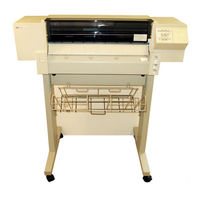
HP Designjet 220 Manuals
Manuals and User Guides for HP Designjet 220. We have
6
HP Designjet 220 manuals available for free PDF download: Service Manual, Upgrade And Replacement Instructions, Upgrade Kit, Configuration Manual, Setting Up
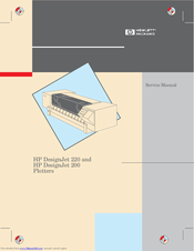
HP Designjet 220 Service Manual (246 pages)
Brand:
HP
| Category:
Plotter
| Size: 6.95 MB
Table of Contents
Using this Manual
4
Table of Contents
5
Safety Symbols
13
Product Information
15
Description
16
Applications
16
Graphic Languages
16
Interfaces
16
Network Connections
16
Memory
16
Accuracy
17
Resolution
17
Plotting Time
17
Legs and Media bin
17
Media Types
17
Media Sizes
18
Media Margins
18
Other Plotter Features
18
Upgrading a Designjet 200
18
Site Planning and Requirements
19
Power Requirements
20
Choosing an Interface Cable (more ' User's Guide)
20
Choosing a Suitable Plotter Environment (more ' User's Guide)
21
Environmental Specifications
21
Plotter Dimensions and Weight
21
Installation and Configuration
23
Unpacking and Assembling the Plotter
24
Inspecting the Plotter for Damage
25
Repacking the Plotter
25
Assembling the Legs and bin (Optional)
26
Using the Plotter (more ' User's Guide)
28
Installing the Plotter (more ' User's Guide)
28
C3187 90000 Contents
28
Configuring the Plotter (more ' User's Guide)
29
Verifying Plotter Operation
29
Power on Self Test
29
Demonstration Plot
29
Example of Setup Sheet
30
Preventive Maintenance
31
Cleaning the Plotter
32
General Cleaning
32
Cleaning the Drive Roller
32
Functional Overview
33
Loading the Media
34
Entry Platen
34
Sensing Media Presence
34
Media Sensor
34
Gripping the Media
38
Pinch Arms
38
Pinch Arm Sensor
38
Advancing the Media
39
Media Drive Mechanics
39
Media Drive Accuracy
39
Providing a Force on Top of the Media
40
Bail
40
Bail Lift Mechanics
40
Bail Sensor
40
Stretching the Media
41
Overdrive
41
Moving the Carriage
41
Carriage Drive Mechanics
41
Detecting the Media Edges
42
Line Sensor
42
Media Margins
42
Media Sizes
42
Providing Ink
43
Print Cartridges
43
Drop Growth
43
Important Parameters
44
Cartridge Chutes
44
Electrical Contact
44
Carriage PCA
44
Producing an Image
45
Raster Technology
45
Resolution (Dots Per Inch)
45
Dot Size
46
Too Much Ink
46
Dot Depletion
46
Print Quality
46
Draft Mode
46
Final Mode
46
Enhanced Mode
46
Print Mode Characteristics
47
Designjet 200
47
Designjet 220
47
Aligning the Cartridges
48
Servicing the Cartridges
49
Service Station
49
Wiping
49
Capping
50
Spitting
50
Cooling the Electronics
50
Fan
50
System Data Flow
51
Input/Output
51
Parser
51
Display List
51
Converters
52
Swath Holding Area
52
Swath Manager
52
Print Engine Controller
52
Swath RAM
52
Cartridge Interface ASIC
52
Carriage ASIC and Cartridge Drivers
52
Plotter Architecture
53
Main PCA
54
Main Processor System
55
Main Processor
55
Rom
55
Processor Support ASIC
56
Shuffler ASIC and Swath Memory
56
Input/Output Interfaces
56
What Is Bi Tronics
56
Serial Hardware
57
Serial Input/Output Initialization
57
Dram
57
Power on Reset Signals
57
Servo Processor System
58
Servo Processor
58
Processor Support ASIC
58
Front Panel Interface
59
Stepper Motor Driver
59
Carriage Processor Interface
59
Sensors
59
Eerom
59
Power Components
60
Carriage and Media Motor Drivers
60
Print Cartridge Voltage Regulator
60
Fan Driver
60
Carriage PCA
61
Carriage Processor System
61
Carriage Processor
61
Nozzle Timing ASIC
62
Servo Processor Interface
62
A/D Converter
62
Print Cartridges
62
Line Sensor
62
Front Panel PCA
63
Leds
63
Key Pad
63
Power Supply
64
Removal and Replacement
66
Safety Precautions
66
ESD Precautions
66
Reassembly
66
Required Tools
67
Repair Procedures
69
Removing the Electronics Enclosure Cover
69
Removing the Memory Module ,DRAM SIMM
71
Removing the Main PCA
73
Removing the Power Supply PCA
76
Removing the Fan
78
Removing the Window
79
Removing the Center Cover
80
Removing the Left Endcover
82
Removing the Right Endcover
83
Removing the Automatic Cartridge Adjust Linkage
84
Removing the Stepper Motor
85
Removing the Pinch Arm Sensor
87
Removing the Window Sensor
88
Removing the Media Sensor
90
Replacing the Media Sensor Flags
92
Removing the Trailing Cable
93
Removing the Front Panel Assembly
96
Removing the Front Panel PCA and LED Assembly
98
Removing the Carriage (y Axis) Motor
99
Removing the Media (X Axis) Motor
101
Removing the Encoder Strip
103
Reinstalling the Encoder Strip
105
Removing the Trailing Cable Guide
107
Removing the y Tensioner and Housing
109
Removing the Cartridge Carriage and Main Drive Belt
112
Removing the Bail Sensor
119
Removing the Bail
120
Removing the Service Station
121
Removing the Overdrive Roller
124
Removing the Overdrive Enclosure
126
Re Installing the Overdrive Enclosure
127
Removing the Entry Platen
129
Re Installing the Entry Platen
131
Removing the Drive Roller
133
Removing the Automatic Bail Lift Mechanism
135
Removing the Pinch Arm Lift Mechanism
136
Calibrations
140
When to Calibrate the Plotter
140
Service Mode
140
Front Panel Keys in Service Mode
141
Performing Tests and Calibrations
141
Cartridge Alignment
142
Accuracy Calibration
144
Bail Calibration
146
Media Sensor Calibration
147
Setup Sheet Calibration
148
Troubleshooting
149
Power on
150
Power on Self Test
150
Extended Power on Self Test
151
Mechanical Initialization
151
What You Should See and Hear
152
Errors Indicated by Leds
153
User Errors
153
Error
153
System Errors
155
Firmware Code Revision Level
159
Troubleshooting Tips
159
Repair + Calibrate
159
Print Quality
159
Diagnosing Problems
159
Other Tips
159
Servo Control System Failures
160
Media Axis (X Axis) Shutdown
160
Carriage Axis (y Axis) Shutdown
160
Frequent Cartridge Failure
160
Remove Tape and Align Cartridges
160
Damaged Encoder Strip
160
Incompatibility between Carriage and Firmware
160
Misaligned Cartridge Caps
161
Function of the Cartridge Caps
161
What Can Cause Cap Misalignment
161
Checking Cartridge Cap Alignment
161
Bail Lift Mechanism Failure
162
Normal Bail Lift Sequence
162
Problems
162
Teflon Washers Versus Cam Gear Support
162
Cartridge Carriage Rubbing against Encoder Strip
163
Premature Wearing of Drive Belts
163
Sensor Does Not Correctly Find Media Edge
163
Last Swath Is Clipped When Replotting
163
Plots Joined or Not Plotted
164
HP GL Timeout
164
Incompatibility between Trailing Cable and Main PCA
164
Incorrect Line Widths
164
Ink Smearing
164
Add Starwheel Mount
164
Change Carriage Rear Bushing
164
Plotter Won't Read Setup Sheet; Plots Solid Black Area Fill
165
Problems in Loading Media
165
Long Media Doesn't Load
165
Translucent Media Doesn't Load
165
Binding, or Missing Sensor Flags
165
Media Skews Badly
165
Service Tests
166
Description
166
Bail Cycle Test
170
Bail Sensor Test
170
Electrical Test
170
Input/Output Test
171
Service Configuration Plot
171
Service Monitor (Data Display)
172
Servo/Encoder Test
172
Stepper Motor Test
172
Window Sensor Test
172
Interpreting the Service Configuration Plot
173
Analyzing the Bar Pattern
173
First Four Bars
173
Fifth and Sixth Bars
173
Seventh Bar
173
Parameters Printed below EEROM Text Block
174
Reading the EEROM Text Block
174
Clearing the EEROM
177
Product History
179
Introduction
180
Serial Number Format
180
Identifying a Printed Circuit Assembly
181
Part Number
181
Potential Ink Smearing Problem
182
Problems Corrected by Firmware Release A.01.01
185
Problems that will be Corrected by Firmware Release A.01.02
186
Eproms and Masked Roms
187
Re Installing Teflon Washers
188
New Bail Lift Mechanism Support
189
Change in Trailing Cable
191
Change in Carriage
192
Change in Bail and Overdrive Parts
192
Parts and Diagrams
193
Exchange Assemblies
194
Replacement Parts
195
Legs and Media bin
197
Window, Center and Bottom Covers
198
Electronics Enclosure
201
Left Endcover and Trim
203
Right Endcover and Trim
205
Carriage Axis Drive (Left End)
207
Service Station
209
Carriage Axis Drive (Right End)
211
Carriage Assembly
213
Media Drive Assemblies
215
Bail and Overdrive Assemblies
219
Pinch Arm Assembly
220
Accessories
222
Line Cord Set
224
Interface Cables
226
Advertisement
HP Designjet 220 Service Manual (246 pages)
HP All in One Printer User Manual
Brand:
HP
| Category:
Plotter
| Size: 7.51 MB
Table of Contents
Part Numbers
4
Removal and Replacement
8
Product History
12
Product Information
15
Graphic Languages
16
Network Connections
16
Plotting Time
17
Legs and Media bin
17
Media Types
17
Other Plotter Features
18
Media Sizes
18
Site Planning and Requirements
19
Installation and Configuration
23
Unpacking and Assembling the Plotter
24
Inspecting the Plotter for Damage
25
Repacking the Plotter
25
Front Panel Setup
28
Power on Self Tests
29
Demonstration Plot
29
Example of Setup Sheet
30
Preventive Maintenance
31
General Cleaning
32
Cleaning the Drive Roller
32
Functional Overview
33
Entry Platen
34
Media Sensor
34
Pinch Arms
38
Media Drive Mechanics
39
Media Drive Accuracy
39
Providing a Force on Top of the Media
40
Operation
40
Bail Sensor
40
Line Sensor
42
Media Margins
42
Media Sizes
42
Print Cartridges
43
Cartridge Chutes
44
Electrical Contact
44
Carriage PCA
44
Raster Technology
45
Resolution (Dots Per Inch)
45
Print Quality
46
Print Mode Characteristics
47
Service Station
49
System Data Flow
51
Display List
51
Print Engine Controller
52
Cartridge Interface ASIC
52
Plotter Architecture
53
Main Pca
54
Main Processor System
55
Input/Output Interfaces
56
Servo Processor System
58
Processor Support ASIC
58
Power Components
60
Carriage Processor System
61
Key Pad
63
Required Tools
67
Repair Procedures
69
Removing the Memory Module ,DRAM SIMM
71
Removing the Main PCA
73
Removing the Power Supply PCA
76
Removing the Fan
78
Removing the Window
79
Removing the Center Cover
80
Removing the Left Endcover
82
Removing the Right Endcover
83
Removing the Automatic Cartridge Adjust Linkage
84
Removing the Stepper Motor
85
Removing the Pinch Arm Sensor
87
Removing the Window Sensor
88
Removing the Media Sensor
90
Replacing the Media Sensor Flags
92
Removing the Trailing Cable
93
Removing the Front Panel Assembly
96
Removing the Front Panel PCA and LED Assembly
98
Removing the Carriage ,Y Axis. Motor
99
Removing the Media ,X Axis. Motor
101
Removing the Encoder Strip
103
Reinstalling the Encoder Strip
105
Removing the Trailing Cable Guide
107
Removing the y Tensioner and Housing
109
Removing the Bail Sensor
119
Removing the Bail
120
Removing the Service Station
121
Removing the Overdrive Roller
124
Removing the Overdrive Enclosure
126
Re Installing the Overdrive Enclosure
127
Removing the Entry Platen
129
Re Installing the Entry Platen
131
Removing the Drive Roller
133
Removing the Automatic Bail Lift Mechanism
135
Removing the Pinch Arm Lift Mechanism
136
When to Calibrate the Plotter
140
Service Mode
140
Front Panel Keys in Service Mode
141
Performing Tests and Calibrations
141
Aligning Cartridges
142
Troubleshooting
149
Power on Self Test
150
Extended Power on Self Test
151
Mechanical Initialization
151
What You Should See and Hear
152
User Errors
153
6 Troubleshooting
154
System Errors
155
Media Axis (X Axis) Shutdown
160
Carriage Axis (y Axis) Shutdown
160
Remove Tape and Align Cartridges
160
Damaged Encoder Strip
160
Incompatibility between Carriage and Firmware
160
Misaligned Cartridge Caps
161
Checking Cartridge Cap Alignment
161
Normal Bail Lift Sequence
162
Teflon Washers Versus Cam Gear Support
162
Add Starwheel Mount
164
Change Carriage Rear Bushing
164
Incompatibility between Trailing Cable and Main PCA
164
Long Media Doesn't Load
165
Translucent Media Doesn't Load
165
Binding, or Missing Sensor Flags
165
Media Skews Badly
165
Service Tests
166
18 Troubleshooting
166
Electrical Test
170
Input/Output Test
171
Service Configuration Plot
171
Service Monitor (Data Display)
172
Servo/Encoder Test
172
Reading the EEROM Text Block
174
Clearing the EEROM
177
Administrative Information
186
Re Installing Teflon Washers
188
Parts and Diagrams
193
Exchange Assemblies
194
Replacement Parts
195
Line Cord Set
224
Interface Cables
226
HP Designjet 220 Upgrade And Replacement Instructions (124 pages)
Tape Library Upgrade and Replacement Instructions
Brand:
HP
| Category:
Storage
| Size: 5.1 MB
Table of Contents
Table of Contents
5
1 Upgrading the Library
13
Upgrade Kit Components
14
Drive Upgrade Kits
14
Table 1-1 DLT Drive Upgrade Kit Components
14
Table 1-2 Ultrium Drive Upgrade Kit Components
14
Fibre Channel Upgrade Kits
15
Table 1-3 Standard Performance Fibre Channel Upgrade Kit (LVDS and HVDS)
15
Table 1-4 High Performance Fibre Channel Upgrade Kit (LVDS)
15
Redundant Power Supply Upgrade Kit
16
Table 1-5 Redundant Power Supply Upgrade Kit
16
Upgrading Drive Capacity
17
Upgrading Firmware
17
Installing a Drive Module
17
Figure 1-1 Installing a Drive Module
18
Figure 1-2 Example of SCSI Cable Connections (Model 2/20)
20
Configuring the New Drive
22
Adding Fibre Channel or Remote Management Cards
23
Figure 1-4 Library Card Positions
24
Upgrading to a Redundant Power Supply
26
Figure 1-5 Adding the Redundant Power Supply Module
27
2 Removing and Replacing Major Library Components
29
Overview
30
Exploded Views of Replaceable Parts (Frus)
32
Front and Back Frus
33
Figure 2-1 Exploded View of Front and Back Frus
33
Table 2-2 Description of Front and Back Frus
34
Cosmetic and Sheetmetal Frus
36
Figure 2-2 Cosmetic and Sheetmetal Exploded View (1 of 2)
36
Table 2-3 Description of Cosmetic and Sheetmetal Frus (1 of 2)
37
Figure 2-3 Exploded View of Cosmetic and Sheetmetal Frus (2 of 2)
38
Table 2-4 Description of Cosmetic and Sheetmetal Frus (2 of 2)
39
Internal Frus
40
Figure 2-4 Exploded View of Internal Frus (1 of 2)
40
Table 2-5 Description of Internal Frus (1 of 2)
41
Figure 2-5 Exploded View of Internal Frus (2 of 2)
42
Table 2-6 Description of Internal Frus (2 of 2)
43
Model 12/140 Frus
44
Table 2-7 Unique Parts for Model 12/140 (5 of 5)
45
Removing and Replacing Cards
46
Removing a Card
46
Replacing a Card
47
Removing and Replacing Drive Modules
49
Drive Replacement Overview
49
Determining Which Drive Has Failed
50
Unloading a Tape from a Drive
50
Taking a Drive Offline
50
Removing a Drive Module
51
Figure 2-8 Ribbon Cable and Connector
51
Figure 2-9 Removing a Drive
52
Installing a Drive Module
54
Figure 2-10 Installing a Drive Module
54
Removing and Replacing the Transport Assembly
56
Accessing the Transport Assembly
56
Figure 2-12 Access to the Transport Assembly
59
Removing the Transport Assembly
60
Replacing the Transport Assembly
61
Figure 2-14 Guide Blocks
61
Figure 2-15 Transport Assembly Position
62
Replacing the Cover
63
Removing and Replacing the Transport Assembly
64
Accessing the Side Panels for Service
64
Figure 2-16 Removing the Cabinet Side Panels
66
Figure 2-17 Removing the Library Side Panels
67
Accessing the Transport Assembly
68
Figure 2-18 Removing the Interconnect Cable
69
Figure 2-19 Removing the Shipping Brackets
70
Figure 2-20 Removing the Retainer Brackets
71
Removing the Transport Assembly
72
Replacing the Transport Assembly
73
Figure 2-22 Transport Assembly Position
73
Re-Installing the Bottom Module
74
Figure 2-23 Checking the Module Alignment
74
Reassembling the Library
75
Removing and Replacing the Vertical Lift Assembly for Models
76
Removing the Vertical Lift Assembly
76
And 12/140
76
Replacing the Vertical Lift Assembly
76
Figure 2-24 Vertical Lift Assembly
77
Removing and Replacing the Motherboard
78
Removing the Motherboard
78
Figure 2-25 Motherboard Cable Connections
79
Figure 2-26 Screw Locations on the Motherboard
80
Figure 2-27 Rotating the Sheet-Metal Cover
81
Figure 2-28 Removing Two Side Panels
83
Figure 2-29 Magazine Lock Harness Cable Connection
84
Figure 2-30 Removing the Motherboard
85
Replacing the Motherboard
86
Removing and Replacing the Power Supply
87
Removing the Power Supply
87
Replacing the Power Supply
88
Removing and Replacing the Redundant Power Supply
89
Replacing the Redundant Power Supply Module
89
Figure 2-32 Replacing the Redundant Power Supply Module
90
Replacing Individual Redundant Power Supply Units
91
Figure 2-33 Replacing Individual Power Supply Units
92
Removing and Replacing the Power Distribution Unit
93
Figure 2-34 Removing the Power Distribution Unit
94
Removing and Replacing the Front Panel Display
95
Removing the Front Panel Display
95
Figure 2-35 Removing the Chin Plate and
95
Replacing the Front Panel Display
96
Figure 2-36 Removing the Front Panel Display
96
Figure 2-37 Connecting the Front Panel
97
Removing and Replacing a Cosmetic Door
98
Removing a Cosmetic Door Face
98
Replacing a Cosmetic Door
98
Figure 2-38 Removing Front Door Face
99
3 Downloading Firware and Interpreting Leds
101
Upgrading Firmware
102
Checking the Firmware Revision
102
Using the Remote Management Card (Library Firmware Only)
103
Using a Firmware Upgrade Tape (Drive Firmware Only)
104
Using a CE Diagnostic Tool (for Service Personnel)
105
Library Leds
107
Front Panel Leds
107
Back Panel Leds
108
Table 3-3 Remote Management Card Leds
110
Table 3-8 High Performance Fibre Channel Controller Leds
115
Table 3-10 Picker Voltage Leds (See (1) in Figure below for LED Locations)
117
Table 3-11 Picker Controller Leds (See (2) for LED Locations)
117
Configuring the Library
119
Configuring the Remote Management Card
120
Install and Configure the Remote Management Card
120
Installation
120
Configuration
120
Configuring the Library for Fibre Channel
122
Configuration
122
Advertisement
HP Designjet 220 Upgrade Kit (75 pages)
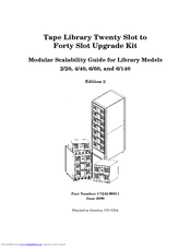
Tape Library Twenty Slot to Forty Slot Upgrade Kit - Modular Scalability Guide
Brand:
HP
| Category:
Storage
| Size: 2.51 MB
Table of Contents
Table of Contents
5
1 Preparing a 2/20 and 4/40 Library for the Upgrade
8
Installation Overview
8
Removing the Cosmetic Enclosure and Cover
9
Removing the Cosmetic Doors
12
Removing the Front Panel Display
14
Preparing the Upgrade Module Chassis
16
2 Upgrading a 20-Slot Library to 40 or 60 Slots
18
Identifying Upgrade Kit Components
18
Upgrading 20-Slot Libraries to 40 Slots
21
Connecting the Library Modules
27
Moving the Front Panel Components and Display
34
Replacing the Display and Viewing Window
34
Replacing the Cosmetic Doors
36
Verifying the Connection
37
Powering on the Library
37
Running Diagnostic Tests
37
Configuring the Library
38
Reconfiguring the Backup Software
38
3 Upgrading a 40-Slot Library to 60 Slots
40
Identifying Upgrade Kit Components
40
Upgrading 40-Slot Libraries to 60 Slots
43
Connecting the Library Modules
46
Moving the Front Panel Components and Display
51
Replacing the Display and Viewing Window
51
Replacing the Cosmetic Doors
53
Verifying the Connection
54
Powering on the Library
54
Running Diagnostic Tests
54
Configuring the Library
55
Reconfiguring the Backup Software
55
4 Upgrading Library Model 6/140
57
Chapter Overview
58
Preparing the Existing Library for Upgrade
59
Removing the Side Panels
59
Removing the Forehead, Top Cover, and Silver
62
Labels
63
Preparing the Upgrade Module for Installation
63
Check the Upgrade Kit Contents
63
Preparing the Upgrade Module
65
Upgrading the 6/100 and 6/120 Model Libraries
66
Securing the Upgrade Module to the Cabinet
67
Reassembling the Upgraded Library
71
Verifying the Connection
74
Powering on the Library
74
Running Diagnostic Tests
74
Configuring the Library
75
Reconfiguring the Backup Software
75
HP Designjet 220 Configuration Manual (36 pages)
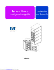
HP Tape Library Configuration Guide
Brand:
HP
| Category:
Storage
| Size: 0.47 MB
Table of Contents
Table of Contents
3
Configuration
5
Windows NT4
6
Sun Solaris
7
HP-UX Hosts
8
HSC or PCI Pass-Through Driver Installation8
10
Creating a Device File for the Robotics Controller8
10
Verifying the Installation10
12
Mpe/IX Hosts11
13
Verifying the Connection
17
Diagnostics
19
Diagnostic Support Tools17
19
HP Library & Tape Tools18
20
Support Tools Manager (STM)19
21
Performing Operations21
23
Using the STM Tools21
23
Reviewing Logs
24
Expert Tools
27
Sysdiag
33
SCSITAC Sections32
34
SCSIDLT Sections
34
HP Designjet 220 Setting Up (7 pages)
HP surestore tape library Setting Up
Brand:
HP
| Category:
Storage
| Size: 1.13 MB
Table of Contents
Tape Library
1
Install and Configure the Host
5
Drivers and Backup Software
5
Getting Started
6
Information Roadmap
6
Front Panel Overview
7
Rear Panel Overview
7
Advertisement
Related Products
HP 252663-D72 - Power Distribution Strip
HP StorageWorks 2100 - Disk System
HP StorageWorks 2012i
HP Surestore 200fx - Optical Jukebox
HP 20 MODULAR SMART ARRAY
HP StorageWorks 2110 - Disk System
HP StorageWorks Ultrium 215i
HP Ultrium 230e
HP StorageWorks Disk System 2405
HP 200 Storage Virtualization System
HP Categories
Desktop
Laptop
Server
Monitor
Switch
More HP Manuals
Login
Sign In
OR
Sign in with Facebook
Sign in with Google
Upload manual
Upload from disk
Upload from URL