Sign In
Upload
Manuals
Brands
HP Manuals
Desktop
Deskpro EX
HP Deskpro EX Desktop PC Manuals
Manuals and User Guides for HP Deskpro EX Desktop PC. We have
1
HP Deskpro EX Desktop PC manual available for free PDF download: Technical Reference Manual
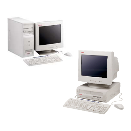
HP Deskpro EX Technical Reference Manual (214 pages)
HP Deskpro EX: Reference Guide
Brand:
HP
| Category:
Desktop
| Size: 1.93 MB
Table of Contents
Table of Contents
9
List of Figures
14
List of Tables
16
Chapter 1 Introduction
19
About this Guide
19
Using this Guide
19
Additional Information Sources
19
Model Numbering Convention
19
Notational Conventions
20
Values
20
Ranges
20
Signal Labels
20
Register Notation and Usage
20
Bit Notation
20
Common Acronyms and Abbreviations
21
Table 1-1. Acronyms Anda
21
Chapter 2 System Overview
25
Introduction
25
Features and Options
26
Standard Features
26
Table 2-1. Feature Difference
26
Options
27
Mechanical Design
28
Cabinet Layouts
29
Front Views
29
Chassis Layouts
31
Board Layout
33
Figure 2-6. System Boardl
33
Ayout
33
System Architecture
34
Figure 2-7. Compaq Deskpro
35
Figure 2-8. Processor Assembly
36
Processors
36
Chipset
38
Support Components
38
Table 2-2. Chipset Comparison
38
Table 2-3. Support Component
38
Mass Storage
39
Processor/Memory Subsystem
39
Serial and Parallel Interfaces
39
System Memory
39
Universal Serial Bus Interface
39
Graphics Subsystem
40
Table 2-4. Graphics Subsystem
40
Audio Subsystem
41
Specifications
41
Table 2-5. Environmentals
41
Table 2-6. Electricals
41
Table 2-7. Physical Specifications
42
Table 2-8. Diskette Drives
42
Table 2-10. Hard Drives
43
Chapter 3 Processor/Memory Subsystem
45
Introduction
45
Processor
45
Figure 3-1. Processor /Memory
45
Celeron Processor
46
Figure 3-2. Celeron Processor
46
Table 3-1. Celeron Processor
46
Figure 3-3. Pentium III Processor
47
Pentium III Processor
47
Table 3-2. Pentium III Processor
47
Processor Upgrading
48
Ycle
48
Memory Subsystem
49
Figure 3-4. System Memorym
51
Subsystem Configuration
52
Table 3-4. Host /Pci Bridgec
52
Chapter 4 System Support
53
Introduction
53
Pci Bus Overview
54
Pci Bus Transactions
55
Figure 4-2. Configurationc
56
Table 4-2. System Board Pci D
57
Pci Bus Master Arbitration
58
Option Rom Mapping
59
Pci Interrupts
59
Pci Power Management Support
59
Pci Sub-Busses
59
Pci Configuration
60
Pci Connector
61
Agp Bus Overview
62
Bus Transactions
62
Agp Configuration
65
Agp Connector
66
Figure 4-8. Universal Agp Bus
66
System Resources
67
Interrupts
67
Figure 4-9. Maskable Interrupt
67
Apic Mode
68
Table 4-8. Maskable Interrupt
68
Non-Maskable Interrupts
69
Direct Memory Access
71
Table 4-10. Default Dma C
71
System Clock Distribution
74
Table 4-13. Clock Generation and Table 4-14. Configurationm
74
Real-Time Clock and Configuration Memory
75
Clearing Cmos
75
Figure 4-10. Configurationm
75
Cmos Archive and Restore
76
Standard Cmos Locations
76
System Management
85
Security Functions
85
Cable Lock Provision
86
Power Management
87
System Status
87
Table 4-15. System Boot /Rom F
87
Temperature Sensing
88
Table 4-16. System Operational
88
System Cooling
89
Figure 4-11. Fan Control Block
89
Register Map and Miscellaneous Functions
90
System I/O Map
90
Table 4-17. System I/O Map
90
82801 Ich General Purpose Functions
91
Table
91
Lpc47B357 I/O Controller Functions
92
Lpc47B357 Gpio R
93
Chapter 5 Input/Output Interfaces
95
Introduction
95
Enhanced Ide Interface
95
Ide Programming
95
Ide Connector
97
Diskette Drive Interface
98
Diskette Drive Programming
99
Table 5-4. Diskette Drivec
99
Table 5-5. Diskette Drivei
99
Diskette Drive Connector
101
Serial Interface
102
Interface
102
Figure 5-3. Serial Interfacec
102
Table 5-7. Db-9 Serial Connector
102
Serial Interface Programming
103
Table
103
Table 5-8. Serial Interfacec
103
Table 5-9. Serial Interfacec
103
Parallel Interface
104
Standard Parallel Port Mode
104
Enhanced Parallel Port Mode
105
Extended Capabilities Port Mode
105
Parallel Interface Programming
105
Table 5-10. Parallel Interface
106
Table
106
Addresses
106
Parallel Interface Connector
107
Figure 5-4. Parallel Interface
107
Table 5-11. Parallel Interface
106
Keyboard/Pointing Device Interface
108
Keyboard Interface Operation
108
Pointing Device Interface Operation
110
Keyboard/Pointing Device Interface Programming
110
Table
110
Table 5-14. Keyboard Interface
110
Keyboard/Pointing Device Interface Connector
112
Table
112
Figure 5-6. Keyboard or Pointing
113
Table 5-16. Keyboard /Pointing
113
Universal Serial Bus Interface
114
Usb Data Formats
114
Usb Programming
116
Usb Control R Table
116
Usb Interfacec
116
Table
116
Usb Connector
117
Usb Cable Data
117
Figure 5-9. Universal Serialb
117
Table
117
Audio Subsystem
118
Functional Analysis
118
Figure 5-10. Audio Subsystem
119
Ac97 Audio Controller
120
Ac97 Link Bus
120
Audio Codec
121
Ac'97 Audioc
121
Audio Programming
122
Table
122
Audio Specifications
123
Table 5-23. Audio Subsystem
123
Network Support
124
Pci Ver. 2.2 Support
124
Alert-On-Lan Support
124
Aol Events
124
Table
124
Remote System Alert Support
126
Figure 5-14. Remote Sensea
126
Table 5-25. Remote Systema
127
Chapter 6 Embedded Graphics Subsystem
129
Introduction
129
Feature Summary
129
815-Based Graphics Functional Description
130
Figure 6-1. 815E-Based Graphics
130
Display Modes
132
Table 6-1. Intel Graphicsd
132
815-Based Graphics Programming
133
Monitor Power Management Control
133
815-Based Graphics
133
Table 6-3. Monitor Powerm
133
Table
133
Monitor Connector
134
Upgrading 815-Based Graphics
134
Table 6-4. Db-15 Monitorc
134
Chapter 7 Power Supply and Distribution
135
Introduction
135
Power Supply Assembly/Control
135
Figure 7-1. Power Distribution and Figure 7-2. Deskpro Ex Dt P
135
Power Supply Assembly
136
Power Control
137
Wake up Events
138
Power Distribution
139
5/12 VDC Distribution
139
Figure 7-3. Deskpro Ex Mt P
140
Low Voltage Distribution
141
Figure 7-4. Low Voltages
141
Signal Distribution
142
Figure 7-5. Signal Distribution
142
Figure 7-6. Header Pinouts
143
Chapter 8 Bios Rom
146
Rom Flashing
146
Upgrading
146
Table 8-1. Boot Block Codes
146
Changeable Splash Screen
147
Boot Functions
148
Boot Device Order
148
Network Boot (F12) Support
148
Memory Detection and Configuration
149
Boot Error Codes
149
Table 8-2. Boot Error Codes
149
Setup Utility
150
Table 8-3. Setup Utilityf
150
Client Management Functions
156
Table 8-4. Client Management
156
Edid Retrieve
158
System ID and Rom Type
158
Drive Fault Prediction
159
Temperature Status
159
Pnp Support
159
Table 8-5. Pnp BIOS Functions
159
Smbios
160
Power Management Functions
161
Independent Pm Support
161
System Standby
162
Acpi Support
163
Apm 1.2 Support
163
Apm Bios Functions
164
System Timer
165
Usb Legacy Support
167
Appendix A Error Messages and Codes
169
Introduction
169
Beep/Keyboard Led Codes
169
Table A-1. Beep /Keyboard
169
A.1 Introduction
169
A.2 Beep/Keyboard Led Codes
169
Power-On Self Test (Post) Messages
170
Table A-2. Power -O N Selft
170
System Error Messages
171
Table A-3. System Errorm
171
Memory Error Messages
172
Keyboard Error Messages
172
Table A-4. Memory Errorm
172
Table A-5. Keyboard Error
172
A.6 Keyboard Error Messages (30 X - XX )
172
Printer Error Messages
173
Video (Graphics) Error Messages
173
Table A-6. Printer Errorm
173
Table A-7. Video (Graphics ) E
173
Diskette Drive Error Messages
174
Serial Interface Error Messages
174
Table A-8. Diskette Drivee
174
Table A-9. Serial Interface
174
Table A-10. Serial Interface
174
A.10 Serial Interface Error Messages (11 XX - XX )
174
A.11 Modem Communications Error Messages (12 XX - XX )
175
Modem Communications Error Messages
175
Hard Drive Error Messages
176
System Status Error Messages
176
Table A-11. System Statuse
176
Table A-12. Hard Drive Error
176
Table A-13. Hard Drive Error
176
A.12 System Status Error Messages (16 XX - XX )
176
A.13 Hard Drive Error Messages (17 XX - XX )
176
Hard Drive Error Messages
177
Video (Graphics) Error Messages
177
Table A-14. Hard Drivem
177
A.14 Hard Drive Error Messages (19 XX - XX )
177
A.15 Video (Graphics) Error Messages (24 XX - XX )
177
Audio Error Messages (3206- XX
178
DVD/CD-Rom Error Messages
178
Network Interface Error Messages
178
Table A-15. Audio Errorm
178
Table A-16. DVD/CD-Rom D
178
Table A-17. Network Interface
178
A.17 DVD/CD-Rom Error Messages (33 XX - XX )
178
A.18 Network Interface Error Messages (60 XX - XX )
178
A.19 Scsi Interface Error Messages (65 XX - XX , 66 XX - XX , 67 XX - XX )
179
Pointing Device Interface Error Messages (8601- XX
179
Scsi Interface Error Messages
179
Table A-18. Scsi Interfacee
179
Table A-19. Pointing Device
179
Appendix B Ascii Character Set
181
Introduction
181
Figure B-1. Ascii Character
181
B.1 Introduction
181
Appendix C Keyboard
183
Introduction
183
C.1 Introduction
183
Keystroke Processing
184
C.2 Keystroke Processing
184
Figure C-1. Keystrokep
184
Figure C-2. Ps/2 Keyboard -T
185
Ps/2-Type Keyboard Transmissions
185
Usb-Type Keyboard Transmissions
186
C.2.3 Keyboard Layouts
187
Figure C-3. U.s. English
187
Figure C-4. National
187
Keyboard Layouts
187
Figure C-5. U.s. Englishw
188
Figure C-6. National Windows
188
Figure C-7. 7-Button Easya
189
Figure C-8. 8-Button Easya
189
C.2.4 Keys
190
Keys
190
C.2.5 Keyboard Commands
193
C.2.6 Scan Codes
193
Keyboard Commands
193
Scan Codes
193
Connectors
198
Figure C-9. Ps/2 Keyboardc
198
Figure C-10. Usb Keyboard
198
C.3 Connectors
198
Figure D-1. Compaq /Nvidia
199
D.1 Introduction
199
Appendix D Compaq/Nvidia Vanta Lt Agp Graphics Card
200
Functional Description
200
Figure D-2. Compaq /Nvidia
200
D.2 Functional Description
200
Display Modes
201
D.3 Display Modes
201
Software Support Information
202
D.5 Power Management and Consumption
202
Connectors
203
Monitor Connector
203
D.6 Connectors
203
D.6.1 Monitor Connector
203
Figure D-3. Vga Monitorc
203
Appendix E Compaq/Nvidia M64 Graphics Card
205
Introduction
205
Figure E-1. Compaq
205
Figure E-2. Compaq
205
E.1 Introduction
205
Functional Description
206
E.2 Functional Description
206
Display Modes
207
Table E-1. Nvidia M64 2D G
207
Software Support Information
208
Table E-2. Monitor Power
208
Connectors
209
Monitor Connector
209
Figure E-3. Vga Monitorc
209
Table E-3. Db-15 Monitor
209
E.6 Connectors
209
E.6.2 Monitor Connector
209
Figure E-4. Video Interfacec
210
Video Interface Connector
210
Table E-4. Multimediai
210
Advertisement
Advertisement
Related Products
HP Deskpro EXD
HP Deskpro EXM
HP Deskpro EXS
HP Deskpro EN
HP Deskpro EN Series
HP Deskpro EX Series
HP Deskpro EXS Series
HP Deskpro SB
HP Deskpro 300
HP Deskpro 3000
HP Categories
Desktop
Laptop
Server
Monitor
Switch
More HP Manuals
Login
Sign In
OR
Sign in with Facebook
Sign in with Google
Upload manual
Upload from disk
Upload from URL