Sign In
Upload
Manuals
Brands
Huawei Manuals
Microphone system
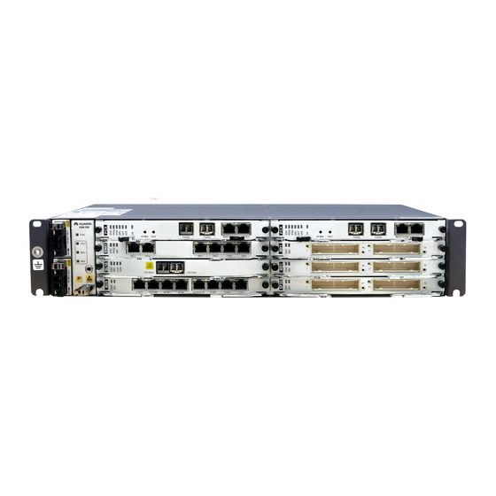
OptiX OSN 550
Huawei OptiX OSN 550 Manuals
Manuals and User Guides for Huawei OptiX OSN 550. We have
1
Huawei OptiX OSN 550 manual available for free PDF download: Configuration Manual
Huawei OptiX OSN 550 Configuration Manual (470 pages)
Multi-Service CPE Optical Transmission System
Brand:
Huawei
| Category:
Microphone system
| Size: 5.69 MB
Table of Contents
Table of Contents
7
About this Document
5
Table of Contents
7
Figures
17
1 Getting Started
21
Starting or Shutting down the U2000
22
Starting the U2000 Server
22
Exiting a U2000 Client
23
Logging in to the U2000 Client
23
Shutting down the U2000 Server
23
Main Windows and Common Operations of the U2000
24
Components of the Client GUI
24
Figure 1-1 Client GUI
25
Key GUI Components
26
Frequently Used Buttons
27
Shortcut Icon
29
Common Shortcut Keys
33
Main Windows
34
Main Topology
35
Workbench
35
Figure 1-2 Main Topology
36
NE Explorer
37
Clock View
38
Browse Alarm
39
Browse Event
39
NE Panel
39
Browse Performance Window
40
2 Creating the Network
41
Creating Nes
43
Creating a Single NE
43
Creating Nes in Batches
45
Configuring the NE Data
46
Configuring the NE Data Manually
46
Replicating the NE Data
48
Uploading the NE Data
48
Checking Board Parameters
49
Table 2-1 SDH Board Parameters
49
Table 2-2 PDH Board Parameters
50
Creating Fibers
51
Creating Fibers Automatically
51
Creating Fibers Manually
52
Creating DCN Communication Cable
53
Creating Virtual Fibers
53
Creating a Topology Subnet
54
Configuring the Protection Subnet
54
Configuring a Non-Protection Chain
55
Configuring a Non-Protection Ring
56
Creating an MS Ring Protection Subnet
56
Creating a Linear MS Protection Subnet
59
Configuring Clocks
61
Configuring the NE Clock Source
61
Configuring the Clock Source Protection
62
Clock Configuration Parameters
63
Managing External Clock Sources
63
Table 2-3 Parameters for Configuring the Output Phase-Locked Source Table of an External Clock
64
Table 2-4 Parameters for Configuring the 2M Phase-Locked Source Attributes of an External Clock
65
Configuring Clock Protection and Restoration
67
Table 2-5 Parameters Used for Configuring Clock Protection and Restoration
67
Clock Quality and Status Management
70
Table 2-6 Parameter Description: Clock Synchronization Status
70
Retiming Management
72
Table 2-7 Parameters Used for Retiming
72
Configuring the Orderwire Phone
73
Configuring the Orderwire
73
Configuring the Conference Calls
74
Configuring the Broadcast Data Service
76
Configuring the F1 Data Service
77
Orderwire Configuration Parameters
77
Configuring Orderwire Phones
77
Table 2-8 Parameters for Configuring Orderwire Phones
78
Configuring F1 Data Interfaces
79
Table 2-9 Parameters for Configuring F1 Data Interfaces
79
Configuring Broadcast Data Interfaces
80
Table 2-10 Parameters for Configuring Broadcast Data Interfaces
80
3 Configuring SDH Services
83
Basic Concepts
85
Configuring Services on the Non-Protection Chain
86
Figure 3-1 Networking Diagram of the Non-Protection Chain
86
Networking Diagram
86
Figure 3-2 Signal Flow and Timeslot Allocation of the Services on the Non-Protection Chain
87
Per-NE Configuration Procedure
87
Signal Flow and Timeslot Allocation
87
End-To-End Configuration Process
89
Configuring Services on the Non-Protection Ring
91
Figure 3-3 Networking Diagram of the Non-Protection Ring
91
Networking Diagram
91
Signal Flow and Timeslot Allocation
91
Figure 3-18 Signal Flow and Timeslot Allocation
92
Figure 3-4 Signal Flow and Timeslot Allocation of the Services on the Non-Protection Ring
92
Per-NE Configuration Process
92
End-To-End Configuration Process
95
Configuring 1+1 Linear MSP Services
97
Figure 3-5 Networking Diagram of the 1+1 Linear MSP Services
97
Networking Diagram
97
Signal Flow and Timeslot Allocation
97
Figure 3-6 Signal Flow and Timeslot Allocation of the 1+1 Linear MSP Services
98
Huawei Proprietary and Confidential Issue
102
End-To-End Configuration Process
103
Per-NE Configuration Process
103
Configuring 1:1 Linear MSP Services
103
Figure 3-12 Signal Flow and Timeslot Allocation
103
Figure 3-7 Networking Diagram of the 1:1 Linear MSP Services
103
Networking Diagram
103
Signal Flow and Timeslot Allocation
103
Figure 3-8 Signal Flow and Timeslot Allocation of the 1:1 Linear MSP Services
104
Per-NE Configuration Process
104
End-To-End Configuration Process
107
Configuring Two-Fiber Unidirectional MSP Services
108
Networking Diagram
108
Figure 3-9 Networking Diagram of the Services on the Two-Fiber Unidirectional MSP Ring
109
Signal Flow and Timeslot Allocation
109
Figure 3-10 Signal Flow and Timeslot Allocation of the Two-Fiber Unidirectional MSP Services
111
Per-NE Configuration Process
111
End-To-End Configuration Process
117
Configuring the Two-Fiber Bidirectional MSP Services
119
Networking Diagram
119
Figure 3-11 Networking Diagram of the Services on the Two-Fiber Bidirectional MSP Ring
120
Signal Flow and Timeslot Allocation
120
Per-NE Configuration Process
121
Signal Flow and Timeslot Allocation
121
End-To-End Configuration Process
124
Configuring Services on the SNCP Ring
126
End-To-End Configuration Process
126
Networking Diagram
126
Per-NE Configuration Process
126
Signal Flow and Timeslot Allocation
126
Figure 3-13 Networking Diagram of the Services on the SNCP Ring
127
Per-NE Configuration Process
128
End-To-End Configuration Process
131
Configuring Services on the SNCP Ring with a Non-Protection Chain
133
Networking Diagram
134
Per-NE Configuration Process
134
Signal Flow and Timeslot Allocation
134
Figure 3-15 Networking Diagram of the Services on the SNCP Ring with a Non-Protection Chain
135
Per-NE Configuration Process
136
End-To-End Configuration Process
141
Configuring Service on the MSP Ring with a Non-Protection Chain
143
Networking Diagram
143
Figure 3-17 Networking Diagram of the Services on the Two-Fiber Bidirectional MSP Ring with a Non-Protection Chain
144
Figure 3-14 Signal Flow and Timeslot Allocation
145
Figure 3-16 Signal Flow and Timeslot Allocation
145
Signal Flow and Timeslot Allocation
146
End-To-End Configuration Process
148
Protection Configuration Parameters
150
SNCP Configuration
150
Table 3-1 Parameters for Configuring the SNCP
150
Configuring the Multiplex Section Protection
151
Table 3-2 Parameters for Configuring the MSP
152
4 Configuring Ethernet Services
155
Service Types
157
Figure 4-1 EPL Services
157
Table 4-1 Corresponding Relations between the External Ports and the Vctrunks (EPL Services)
157
Figure 4-2 PORT-Shared EVPL Services
158
Figure 4-3 VCTRUNK-Shared EVPL Services
158
Figure 4-4 EPLAN Services (IEEE 802.1D Bridge)
159
Figure 4-5 EVPLAN Services (IEEE 802.1Q Bridge)
160
Basic Concepts
161
Figure 4-6 EVPLAN Services (IEEE 802.1Ad Bridge)
161
Formats of Ethernet Frames
162
Figure 4-7 Formats of Ethernet Frames
163
Figure 4-8 Positions of the TPID and TCI in the Frame Structure
163
Table 4-4 Tag Types Defined by Using the TPID
163
Figure 4-10 TCI Structure of the S-TAG
164
Figure 4-9 TCI Structure of the C-TAG
164
Auto-Negotiation
165
Figure 4-11 External Ports and Internal Ports on Ethernet Boards
165
Internal Ports and External Ports
165
Figure 4-12 Waveform of a Single FLP
166
Figure 4-13 Consecutive FLP and NLP Bursts
166
Flow Control
167
Encapsulation and Mapping Protocol
168
Figure 4-14 Structure of the PAUSE Frame
168
Virtual Concatenation
169
Figure 4-15 VC-3-XV/Vc4-XV Multiframe and Sequence Indicator
171
Tag Attribute
171
Table 4-5 Processing Mode of Data Frames on Ports with Different Tags
172
Bridge
173
Figure 4-16 Relations between Vbs, Lps, Ports, and Vctrunks
173
Figure 4-17 Transparent Bridge and Virtual Bridge
174
Table 4-6 Transparent Bridge and Virtual Bridge
174
Table 4-7 Types of Bridges Supported by the Ethernet Boards
175
Flow of Configuring Ethernet Services
176
Flow of Configuring EPL Services
177
Figure 4-18 Flow of Configuring EPL Services
178
Table 4-8 Flow of Configuring EPL Services
178
Flow of Configuring EVPL Services
179
Figure 4-19 Flow of Configuring EVPL Services
180
Table 4-9 Flow of Configuring EVPL Services
180
Flow of Configuring EPLAN Services
181
Figure 4-20 Flow of Configuring EPLAN Services
182
Table 4-10 Flow of Configuring EPLAN Services
182
Flow of Configuring EVPLAN Services
184
Figure 4-21 Flow of Configuring EVPLAN Services
185
Table 4-11 Flow of Configuring EVPLAN Services
186
Configuring EPL Services on an Ethernet Transparent Transmission Board
187
Networking Diagram
187
Figure 4-22 Networking Diagram of the EPL Services
188
Figure 4-23 Signal Flow and Timeslot Allocation (Ethernet Transparent Transmission Board)
189
Signal Flow and Timeslot Allocation
189
Table 4-12 Parameters of External Ports on the Ethernet Boards
189
Configuration Process
190
Table 4-13 Parameters of Internal Ports on the Ethernet Boards
190
Configuring EPL Services on an Ethernet Switching Board
197
Figure 4-24 Networking Diagram of the EPL Services
198
Networking Diagram
198
Figure 4-25 Signal Flow and Timeslot Allocation (Ethernet Switching Board)
199
Signal Flow and Timeslot Allocation
199
Table 4-14 Parameters of External Ports on the Ethernet Boards
199
Configuration Process
200
Table 4-15 Parameters of Internal Ports on the Ethernet Boards
200
Table 4-16 Parameters of the EPL Services
200
Configuration Process (End-To-End Mode)
210
Table 4-17 Parameters of the VC-4 Server Trail between User A1 and User A2
211
Table 4-18 Parameters of the VC-4 Server Trail Route between User A1 and User A2
211
Table 4-19 Parameters of the EPL Services between User A1 and User A2
212
Configuring PORT-Shared EVPL (VLAN) Services
213
Networking Diagram
213
Signal Flow and Timeslot Allocation
213
Table 4-20 Parameters of Port Attributes for User A1 and User A2
213
Figure 4-26 Networking Diagram for Configuring PORT-Shared EVPL (VLAN) Services
214
Figure 4-27 Signal Flow and Timeslot Allocation
215
Table 4-21 Parameters of External Ports on the Ethernet Boards
216
Table 4-22 Parameters of Internal Ports on the Ethernet Boards
216
Table 4-23 Parameters of the PORT-Shared EVPL (VLAN) Services
216
Configuration Process
217
Configuring VCTRUNK-Shared EVPL (VLAN) Services
226
Figure 4-28 Networking Diagram for Configuring VCTRUNK-Shared EVPL (VLAN) Services
227
Networking Diagram
227
Signal Flow and Timeslot Allocation
228
Configuration Process
229
Table 4-26 Parameters of the VCTRUNK-Shared EVPL (VLAN) Services
229
Configuring EPLAN Services (IEEE 802.1D Bridge)
237
Networking Diagram
237
Signal Flow and Timeslot Allocation
237
Figure 4-30 Networking Diagram for Configuring EPLAN Services (IEEE 802.1D Bridge)
238
Figure 4-31 Signal Flow of and Timeslot Allocation
238
Table 4-27 Parameters of External Ports on the Ethernet Boards
239
Table 4-28 Parameters of Internal Ports on the Ethernet Boards
239
Configuration Process
240
Table 4-29 Parameters of Ethernet LAN Services (IEEE 802.1D Bridge)
240
Configuring EVPLAN Services (IEEE 802.1Q Bridge)
250
Networking Diagram
250
Signal Flow and Timeslot Allocation
250
Figure 4-32 Networking Diagram for Configuring EVPLAN Services (IEEE 802.1Q Bridge)
251
Figure 4-33 Signal Flow of and Timeslot Allocation to EVPLAN Services (IEEE 802.1Q Bridge)
252
Table 4-30 Parameters of External Ports on the Ethernet Boards
253
Table 4-31 Parameters of Internal Ports on the Ethernet Boards
253
Table 4-32 Parameters of Ethernet LAN Services (IEEE 802.1Q Bridge)
254
Configuration Process
255
Configuring EVPLAN Services (IEEE 802.1Ad Bridge)
269
Figure 4-29 Signal Flow and Timeslot Allocation
269
Networking Diagram
269
Figure 4-34 Networking Diagram for Configuring EVPLAN Services (IEEE 802.1Ad Bridge)
270
Figure 4-35 Signal Flow of and Timeslot Allocation to EVPLAN Services (IEEE 802.1Ad Bridge)
271
Signal Flow and Timeslot Allocation
271
Table 4-24 Parameters of External Ports on the Ethernet Boards
272
Table 4-25 Parameters of Internal Ports on the Ethernet Boards
272
Configuration Process
273
Table 4-35 Parameters of Ethernet LAN Services (IEEE 802.1Ad Bridge)
273
Ethernet Port Configuration Parameters
284
Basic Attributes
285
Table 4-36 Parameters for Configuring the Basic Attributes of an Ethernet Port
285
Flow Control
286
Network Attributes
287
Table 4-37 Parameters for Configuring Flow Control of an Ethernet Port
287
Advanced Attributes
288
Table 4-38 Parameters for Configuring Network Attributes of an Ethernet Port
288
Table 4-39 Parameters for Configuring the Advanced Attributes of an Ethernet Port
288
Table 4-40 Parameters for Configuring the Tag Attributes of an Ethernet Port
291
TAG Attributes
291
Encapsulation/Mapping
292
Table 4-41 Parameters for Configuring the Encapsulation and Mapping of an Ethernet Port
292
Bound Path
293
Table 4-42 Parameters for Bound Path
293
Ethernet Service Configuration Parameters
294
Configuring Ethernet Private Line Services
294
Table 4-43 Parameters for Configuring Ethernet Private Line Services
295
Configuring Ethernet Private Network Services
304
Table 4-44 Parameters for Configuring Ethernet Private Network Services
304
Table 4-45 Parameters for Configuring Service Mount
305
Table 4-46 Parameters for Configuring VLAN Filtering
307
Table 4-47 Parameters for Configuring VLAN Unicast
307
Table 4-48 Parameters for Configuring Disable MAC Address
308
Table 4-49 Parameters for Bound Path
308
5 Modifying the Configuration Data
311
Changing the Values of NE Attributes
312
Changing the NE ID
312
Changing the NE Name
313
Deleting an NE
313
Changing the Parameter Values of the Gateway NE
314
Changing the Gateway NE of a Non-Gateway NE
315
Modifying the Board Configuration Data
316
Adding Boards
316
Deleting Boards
317
Modifying Board Configuration Parameters
317
Modifying the Fiber Configuration Data
318
Changing Fiber/Cable Information
318
Deleting Fibers
318
Deleting DCN Communication Cables
319
Modifying the Service Configuration Data
319
Modifying SDH Services
319
Deleting Ethernet Private Line Services
321
Deleting SDH Services
321
Deleting EPLAN Services
322
Deleting EVPLAN Services
323
Modifying the Protection Subnet
323
Changing the Values of Protection Subnet Parameters
324
Deleting Protection Subnets
324
6 Equipment Information
327
Service Support Capability of Ethernet Boards
328
Requirements for Binding Paths with Vctrunks on Ethernet Boards
328
Table 6-1 Service Support Capability of Ethernet Boards
328
Table 6-2 Requirements for Binding Paths with Vctrunks on Ethernet Boards
328
Ethernet Service Bandwidths Carried by Vctrunks of Ethernet Boards
329
7 List of Parameters
331
Port Attributes (Ethernet Port)
336
Maximum Frame Length (Ethernet Port Attribute)
337
Non-Autonegotiation Flow Control Mode (Ethernet Port Attribute)
338
Autonegotiation Flow Control Mode (Ethernet Port Attribute)
339
MAC Loopback (Ethernet Port Attribute)
340
PHY Loopback (Ethernet Port Attribute)
340
Qinq Type Area
341
Loop Detection (Ethernet Port Attribute)
342
Loop Port Shutdown (Ethernet Port Attribute)
343
Traffic Threshold(Mbit/S)(External Ethernet Port Attribute)
343
Broadcast Packet Suppression Threshold (Ethernet Interface Attributes)
344
Broadcast Packet Suppression (Ethernet Interface Attributes)
345
Zero-Flow Monitor (Ethernet Interface Attributes)
345
Port Traffic Threshold Time Window(Min)
346
Jumbo Frame Type
347
Default VLAN ID (Ethernet Port Attribute)
347
VLAN Priority (Ethernet Port Attribute)
348
Entry Detection (Ethernet Port Attribute)
349
Tag
349
Mapping Protocol
351
Scramble
352
Table 7-1 the Mapping Protocol Supported by each Type of Board
352
Set Inverse Value for CRC
353
Table 7-2 Scramble Supported by each Type of Board
353
Check Field Length
354
Table 7-3 the Length of the CRC Field Supported by each Type of Board
354
FCS Calculated Bit Sequence
355
Table 7-4 FCS Calculated Bit Sequence Supported by each Type of Boards
355
Operation Type (EPL Service)
356
Service Type (EPL Service)
358
Encapsulation Format of P Port (Network Attributes)
358
Figure 7-1 Encapsulation Format of Martinioe
359
C-VLAN and S-VLAN
360
Figure 7-2 Encapsulation Format of Stack VLAN
360
VLAN ID (for Creation of Ethernet Virtual Private Lines)
361
Bridge Learning Mode (Ethernet LAN Service)
361
MEP ID (Ethernet OAM)
362
Maintenance Point Type (Ethernet OAM)
363
CC Status (Ethernet OAM)
364
Test Result (LB and LT Test)
364
Responding MP Type (Ethernet LT Test)
365
Hop Count (Ethernet LT Test)
365
Packet Length (Ping Test)
366
Figure 7-3 an Example of Number of Hops
366
Timeout (Ping Test)
367
Detect Attempts
367
Send Direction (Ethernet Test)
368
Error Frame Monitor Window (Ms)
369
Error Frame Monitor Threshold(Entries)
369
Error Frame Period Window(Frames)
370
Error Frame Monitor Threshold(Frames)
371
Error Frame Second Window (S)
372
Error Frame Second Threshold(S)
372
Enable OAM Protocol
373
Huawei Proprietary and Confidential Issue
373
OAM Working Mode
373
Remote Alarm Support for Link Event
374
Unidirectional Operation
375
Loopback Status (OAM Parameter)
376
Flow Type (Flow Configuration)
376
Bound CAR (Flow Configuration)
377
Bound Cos (Flow Configuration)
378
CAR ID (CAR Configuration)
379
Enabled/Disabled (CAR Configuration)
379
Committed Information Rate (Kbit/S) (CAR Configuration)
380
Committed Burst Size (Kbyte) (CAR Configuration)
381
Peak Information Rate (Kbit/S) (CAR Configuration)
381
Maximum Burst Size (Kbyte) (CAR Configuration)
382
Cos ID (Cos Configuration)
383
Cos Type (Cos Configuration)
383
Cos Priority (Cos Configuration)
384
Table 7-5 Cos Priority of the Simple Type
384
Table 7-6 Cos Priority of the VLAN Priority Type
385
Table 7-7 Cos Priority of the DSCP Type
385
Table 7-8 Cos Priority of the IPTOS Type
385
Port Priority (Link Aggregation)
386
System Priority (Link Aggregation)
386
Status (Link Aggregation)
387
Load Sharing(Ethernet Link Aggregation)
388
Protocol Enabled (Spanning Tree)
389
Protocol Type (Spanning Tree Protocol)
389
Priority (Bridge Parameters)
390
Max Age(S)
391
Hello Time(S) (Spanning Tree)
391
Forward Delay(S) (Spanning Tree)
392
Txholdcount(Per Second) (Spanning Tree)
393
Root Path Cost
393
Hold Count (Spanning Tree)
394
Port ID
394
Designated Path Cost
395
Table 7-9 Recommended Values of the Port Path Cost
395
Designated Root Bridge Priority
396
Designated Bridge Priority(Spanning Tree)
397
Designated Bridge MAC Address (Spanning Tree)
397
Edge Port Status (Spanning Tree)
398
Point to Point Attributes(External Ethernet Port Attributes)
399
Enabling LCAS
400
LCAS Mode
400
Hold-Off Time (Ms) (LCAS)
401
WTR Time (S) (LCAS)
402
Tsd (Lcas)
402
Min Members - Transmit Direction
403
Bearer Mode
404
Lpt
404
Port-Type Port Hold-Off Time (Ms)
405
Protocol Enable (IGMP Snooping Protocol)
406
VCTRUNK Port Hold-Off Time (Ms)
406
Multicast Aging Time(Min)
407
Frames to Send
408
Status
408
Set Frame Count
409
Received Response Test Frame Count
410
Test Frames to Receive
410
Send Mode (Ethernet Test)
411
Call Waiting Time(S)
412
Conference Call
412
Phone
413
Available Orderwire Port
414
Data Channel (F1 Data Port)
415
No.(F1 Data Port)
415
Overhead Byte (Broadcast Data Port)
416
Working Mode (Broadcast Data Port)
417
Broadcast Data Sink (Broadcast Data Port)
418
Broadcast Data Source (Broadcast Data Port)
418
External Clock Output Mode When 2M Output Synchronous Source Is Invalid
419
External Clock Output Mode
420
External Clock Output Timeslot
421
External Source Output Threshold
422
Phase-Locked Source Fail Condition
424
Phase-Locked Source Fail Action
425
Clock Source Threshold
426
AIS Alarm Generated
427
B1 BER Threshold-Crossing Generated
428
B2-EXC Alarm Generated
429
Higher Priority Clock Source Reversion Mode
430
Clock Source WTR Time
431
Lock Status
431
Synchronous Source
432
S1 Byte Synchronization Quality Information
433
NE Clock Working Mode
434
Data Output Method in Holdover Mode
435
Retiming Mode
436
Switching Mode (MSP)
437
A Glossary and Acronyms
439
A.1 Numerics
441
A.19
464
Advertisement
Advertisement
Related Products
Huawei OptiX OSN 2500
Huawei OptiX RTN 980L V100
Huawei OptiX RTN 320F
Huawei OptiX RTN 905
Huawei OptiX RTN 980
Huawei OptiX RTN 600
Huawei OptiX OSN 8800 T32
Huawei OSN 3500
Huawei Optix OSN 810
Huawei OptiX OSN 9560
Huawei Categories
Cell Phone
Network Router
Wireless Router
Modem
Network Hardware
More Huawei Manuals
Login
Sign In
OR
Sign in with Facebook
Sign in with Google
Upload manual
Upload from disk
Upload from URL