Sign In
Upload
Manuals
Brands
Husqvarna Manuals
Motorcycle
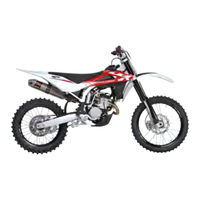
TC 250 2011
Husqvarna TC 250 2011 Manuals
Manuals and User Guides for Husqvarna TC 250 2011. We have
2
Husqvarna TC 250 2011 manuals available for free PDF download: Workshop Manual, Specifications - Operation - Maintenance
Husqvarna TC 250 2011 Workshop Manual (366 pages)
Brand:
Husqvarna
| Category:
Motorcycle
| Size: 25.73 MB
Table of Contents
Table of Contents
5
Foreword, Table of Contents
3
Workshop Manual
3
Table of Contents
5
Important Notices
7
General Information
9
Table of Contents
10
Clutch
11
Cooling
11
Engine
11
Fuel System
11
Ignition
11
Lubrication
11
Primary Drive
11
Starting
11
Timing System
11
Transmission
11
Final Ratios (Tc)
12
Frame
12
Front Brake
12
Front Suspension
12
Rear Brake
12
Rear Suspension
12
Rims
12
Secondary Drive
12
Transmission Ratio (TC)
12
Cold Tire Pressure
13
Electrical Components Location (TC)
13
Electrical Components Location (TE)
13
Electrical Components Location (Txci)
13
Tires
13
Overall Dimensions
14
Capacities
15
Weight
15
Maintenance
17
Troubleshooting
25
Settings and Adjustments
31
Settings and Adjustments
32
Saddle Removal
34
Tank Removal
34
Valve Clearance Adjustment
36
Enrichener Lever Play Adjustment
37
Throttle Cable Adjustment
37
Idle Adjustment
38
Clutch Plate Replacement
39
Hydraulic Clutch Lever Adjustment and Fluid Level Check
40
Front Brake Lever Adjustment and Fluid Level Check
41
Rear Brake Pedal Position Adjustment
42
Rear Brake Fluid Level Check
43
Rear Brake Pedal Free Play Adjustment
43
Engine Oil Level Check
44
Engine Oil Replacement and Mesh Filters-Filter Cartridge Cleaning or Replacement
45
Coolant Level Check
46
Coolant Replacement
46
Air Filter Check (TC)
47
Air Filter Check (te - Txci)
48
Air Filter Cleaning
48
Assembly
49
Secondary Drive Chain Adjustment
50
Chain Lubrication
51
Disassembling and Cleaning
51
Lubricating a Chain Without O-Rings
51
Lubricating an O-Ring Chain
51
Washing a Chain Without O-Rings
51
Suspension Setup According to Track Condition
52
Shock Absorber Adjustment
53
Shock Absorber Spring Preload Adjustment
54
Shock Absorber Compression and Rebound Damping Adjustment
55
Shock Absorber Springs (4)
55
KAYABA Front Fork Adjustment
56
KAYABA Front Fork Springs
57
Steering Angle Adjustment
58
Steering Bearing Clearance Adjustment
58
Changing Handlebar Position and Height
59
Supply Hose Check
60
Exhaust System Check
61
General Procedures
63
General Procedures
64
Foreword
65
Battery Removal (te - Tcxi)
66
Saddle Removal
66
Side Panel Removal
66
Removing the Rear Chassis Complete with Mudguard and Air Box (TC)
67
Removing the Rear Chassis Complete with Mudguard and Air Box (te - Txci)
67
Exhaust System Removal
70
Fuel Tank, Scoops and Spoiler Removal
72
Fuel Pump Removal (TC)
76
Battery-Less (TC)
78
Solenoid Starter Removal (te - Txci)
78
CDI Electronic Control Unit Removal
79
Voltage Regulator Removal
79
Ignition Coil Removal
80
Clutch Hose Removal
81
Horn Removal (TE)
81
Electric Cooling Fan Removal (te - Txci)
82
Engine Removal
83
Secondary Drive Chain Removal
83
Radiator Removal
91
Thermostat Removal (te - Txci)
92
Engine Disassembly
93
Table of Contents
94
Layout of Engine Components
95
Camshaft Removal
96
Cylinder Head Cover Removal
96
Water Pump Body Removal
100
Water Pump Disassembly
100
Cylinder Head Removal
102
Valve Removal
104
Cylinder Removal
106
Piston Removal
106
Flywheel Removal
107
Kick Start Pedal Removal
108
Sprocket Removal
108
Oil Filter Removal
110
Clutch Cover Removal
111
Clutch Disassembly
112
Kick Start Disassembly
115
Slider Removal
115
Starter Motor Removal (TE-Txci)
117
Starter Drive Disassembly (te - Txci)
119
Starter Motor Disassembly (TE-Txci)
119
Gear Shift Pedal and Selector Assembly Removal
122
Oil Pump Disassembly
122
Primary Drive Gear Removal
125
Crankcase Disassembly
126
Gearbox Disassembly
127
Crankshaft Disassembly
129
Engine Overhaul
131
Table of Contents
132
Cleaning Parts
133
Clearances
133
Cylinder Head
133
Valve Seat Refacing
134
Valve Guide
135
Valve Guide Replacement
135
Valve
137
Valve Spring
137
Valve Bucket Inspection
138
Valve Installation
138
Valve Leak Check
139
Camshaft
140
Timing Chain and Gears
140
Timing Chain Tensioners
140
Cylinder
141
Piston
141
Cylinder to Piston Clearance
142
Piston Pin
142
Piston Ring to Cylinder Clearance
143
Piston Rings
143
Big End Axial Clearance
144
Piston Ring to Groove Clearance
144
Crankshaft
145
Crankshaft Straightness
145
Clutch
146
Clutch Spring
147
Friction Plate to Clutch Housing Clearance
147
Oil Pump
149
Drive Bushing Roundness
150
Selector Drum
150
Shifter Forks and Gears
150
Engine Reassembly
151
Table of Contents
152
General
153
Assembly and Lubrication Instructions
154
Crank- Alternator- Lubrication- Left Crankcase Half
154
Tightening Torque Figures
155
Assembly and Lubrication Instructions
156
Gearbox - Gear Shift Control
156
Tightening Torque Figures
157
Assembly and Lubrication Instructions
158
Gearbox - Gear Shift Control
158
Tightening Torque Figures
159
Assembly and Lubrication Instructions
160
Clutch- Kick Start- Lubrication- Right Crankcase Half
160
Tightening Torque Figures
161
Assembly and Lubrication Instructions
162
Right Crankcase Cover
162
Tightening Torque Figures
163
Assembly and Lubrication Instructions
164
Head - Cylinder - Piston - Timing System - Water Pump Spark Plug
164
Tightening Torque Figures
165
Input Shaft (5 SPEED)
166
Output Shaft (5 SPEED)
166
Input Shaft (6 SPEED)
169
Output Shaft (6 SPEED)
169
Crankcase Assembly
172
Gear Shift Control Assembly
177
Kick Start Assembly
181
Timing Chain and Primary Drive Assembly
182
Clutch Assembly
185
Sprocket Installation
187
Flywheel and Starter Motor Installation
188
Assemble the Starter Motor (7)
189
Piston and Cylinder Installation
190
Piston Ring Installation
190
Cylinder Head Gasket Selection Table
192
Cylinder Head Installation
193
Timing Chain Tensioner Installation
195
Camshaft Installation
196
Flywheel Cover Installation
198
Neutral Sensor Installation
199
Cylinder Head Cover, Spark Plug, Oil Feed Hose Installation
200
Starter Motor Seat Cover Installation (TC)
200
Right Crankcase Assembly
201
Blow-By Tube Fitting/Filter (310)
203
Filter and Drain Plug
203
Oil Feed Hose Installation
203
Gear Shift and Kick Start Pedal Installation
204
Installing the Engine and Assembling the Motorcycle
205
Front Suspension
207
Rear Suspension
235
Rear Suspension
236
Lubrication Points (Grease)
237
Rear Shock Absorber
237
Rear Suspension
237
Rear Shock Absorber Removal
239
Disassembling, Servicing and Assembling the Rear Shock Absorber
240
Shock Absorber Inspection
240
Piston Assembly Inspections
243
Seal Replacement
243
Checking the Setting
244
Reservoir Replacement
245
Floating Piston Removal
246
Shock Absorber Assembly
246
Shock Absorber Damping Adjustment
249
Disassembling and Servicing the Swinging Arm
250
Servicing the Rear Suspension Drop Drag Link
251
Servicing the Swinging Arm Shaft
251
Chain Roller, Chain Guide, Chain Slider
252
Brakes
253
Brakes
254
Braking System
255
Brake Disc
256
Checking Brake Pads for Wear / Replacing the Pads
257
Bleeding the Front Braking System
258
Bleeding the Rear Braking System
259
Changing the Fluid
260
Electrical System
263
Table of Contents
264
Key to Wiring Diagram
267
Wiring Diagram (TC)
267
Colour Coding Key
268
Key to Wiring Diagram
268
Wiring Diagram (TE)
268
Colour Coding Key
269
Key to Wiring Diagram
269
Wiring Diagram (Txci)
269
Electrical Components Location (TC)
270
Electrical Components Location (TE)
271
Electrical Components Location (Txci)
275
Checking Generator Stator Windings Resistance
278
Generator No-Load Performance
279
Ignition System (TC)
280
Key to Wiring Diagram
280
Ignition System (te - Txci)
281
Key
281
Key to Wiring Diagram
282
CHARGING SYSTEM (te - Txci)
283
Charging System Wiring Diagram
283
Charging System Inspections
284
Current Loss at the Battery (te - Txci)
284
Regulated Voltage (te - Txci)
284
Voltage Regulator
284
Voltage Regulator/Rectifier Inspection (te - Txci)
284
Voltage Regulator/Rectifier Wiring Diagram
284
ELECTRICAL STARTING SYSTEM (te - Txci)
285
Wiring Diagram
285
Solenoid Starter Inspection (te - Txci)
286
Starter Motor Inspection (te - Txci)
286
Starter Motor Test Curves (te - Txci)
286
Starting System Inspection
286
Checking Coil Windings Resistance
287
Electronic Control Unit (ECU)
288
Spark Plug
288
Gear Position Sensor Inspection (GPS: Gear Position Sensor)
289
BATTERY (te - Txci)
290
Battery Charger
290
Headlamp Adjustment
291
Headlamp Bulbs Replacement
291
Headlamp, Tail Light (Te)
291
Number Plate Bulb Replacement
292
Tail Light Replacement
292
Handlebar Switches
293
Left-Hand Switch (TC)
293
Left-Hand Switch (TE)
293
Colour Coding Key
294
Right-Hand Switch (te - Txci)
294
Fuses
295
Semiconductor Parts
295
Relay Test (te - Txci)
296
Digital Dashboard, Warning Lights (Te)
297
Warning Lights Panel (Txci)
299
CHARGING SYSTEM (te - Txci)
300
Dashboard Replacement (TE)
300
Electronic Ignition System
300
STARTING SYSTEM (te - Txci)
300
Troubleshooting
300
Cable Routing and Electrical Parts Installation Instructions (TC)
302
Fuel Injection Control Unit Position (2) (TC)
302
HT Coil Position (1) (TC)
302
Securing Engine Stop Button Ground Cable to Chassis (TC)
302
Control Unit Connection (TC)
303
Gear Sensor Cable Connection (TC)
303
Ignition Coil Connection (TC)
303
Condenser Connection (TC)
304
Securing the Engine Stop Button Cable (TC)
304
Securing the Wiring (TC)
304
Voltage Regulator Connection (TC)
304
Wiring (te - Txci)
305
CABLE ROUTING and ELECTRICAL PARTS INSTALLATION INSTRUCTIONS "TE - Txci
306
Coil Position te -Txci
306
Relay (1) and Fuses (2) Position (te - Txci)
306
Turning Indicators Flasher (3) (TE) and Solenoid Starter Position (te - Txci)
306
Battery Negative Cable Routing (te - Txci)
307
Electronic Control Unit (5) and Voltage Regulator (6) Position (te - Txci)
307
Securing the Starter Motor/Solenoid Starter Cable (te - Txci)
307
Securing the Engine Ground / Chassis Ground Cables (10)
308
Electrical System Ground
308
Wiring Connection to Voltage Regulator (te - Txci)
308
Connection of Relays and Fuses (te - Txci)
309
Electric Fan Connection (te - Txci)
309
Injector Connection (te - Txci)
309
Ignition Coil Connection (te - Txci)
309
Fuel Pump Connector Position (te -Txci)
310
MAQS Connector (te - Txci)
310
Engine Water Temperature Connector (te - Txci)
310
Lambda Sensor Position and Connector (te - Txci)
310
Securing the Voltage Regulator Ground Cable (9) (te - Txci)
308
Clip Installation on Fuse Holders
311
Ignition and Gear Sensor Cable Connection
311
Routing of Rear Chassis Cables, Tail Light Connection, Flasher Contactor
311
Dashboard Bracket Connectors (TE)
312
Headlamp, Front Turning Indicators, STOP Connection (TE)
312
Rear Stop Connection
312
Routing of Steering Head Tube Wiring
312
Horn Connector (TE)
313
Speed Sensor and Ignition Switch Connectors (TE)
313
Securing the Wiring Harness
314
Securing the Wiring Harness to Rear Chassis Left Side
314
Securing the Wiring Harness to Rear Chassis Right Side
314
Securing the Wiring Harness to the Chassis
314
Engine Cooling
317
Table of Contents
318
Coolant Level Check
319
Cooling Circuit (TC)
320
Engine Cooling System Overhaul (TC)
321
Cooling Circuit (TE-Txci)
322
Engine Cooling System Overhaul (TE-Txci)
323
Hydraulically Controlled Clutch
325
Hydraulically Controlled Clutch
326
Hydraulic Clutch System
327
Draining Clutch Fluid
328
Clutch Master Cylinder Servicing
329
Bleeding the Clutch System
330
Fuel Injection System
331
INJECTION FUEL FEEDING SYSTEM (TE-Txci)
333
Injection Fuel Feeding System (Tc)
334
Operation Manual for "HUSQVARNA SERVICE TOOL" for Injection Fuel Feeding System (TE-Txci)
335
Operation Manual for "HUSQVARNA SERVICE TOOL" for Injection Fuel Feeding System (TC)
337
Fuel Pump Test (TC)
339
Special Tools
341
Tightening Torque Figures
343
Chassis and Wheels
353
Chassis
355
Lubrication Points (Lubricant)
356
Rear Wheel
360
Tightening Torque Figures
361
Wheel Servicing
362
Wheel Axle Warpage
362
Axle Runout over 100 MM
362
Wheel Spokes
363
Wheel Rim Warpage
363
Rear Chain Sprocket, Secondary Drive Sprocket and Chain
364
Tightening Torque Figures
364
Checking Chain and Sprockets for Wear
365
Advertisement
Husqvarna TC 250 2011 Specifications - Operation - Maintenance (296 pages)
Brand:
Husqvarna
| Category:
Motorcycle
| Size: 4.63 MB
Table of Contents
Presentazione
2
Avvertenze Importanti
2
Table of Contents
4
Dati Per L'identificazione
5
Ubicazione Comandi
6
Dati Tecnici
7
Tabella DI Lubrificazione, Rifornimenti
8
Comandi
9
Arresto del Motociclo E del Motore
22
Batteria
29
Appendice
54
Carburante
54
Operazioni DI Preconsegna
55
Cavalletto Laterale
55
Indice Alfabetico
56
Identification Data
61
Vehicle Identification Number (V.I.n.)
61
Control Location
62
Technical Data
63
Controls
65
FUEL COCK (TE-Txci)
65
FUEL INJECTION ENGINE (TE-Txci)
65
Fuel
66
Side Stand
66
Cold Start
67
Double Map Button (Te)
67
Digital Instrument, Warning Lights (Te)
68
Speed / Chrono
69
Speed / Clock
69
Speed / Trip
69
Speed / Digital Rpm
70
WARNING LIGHTS PANEL (Txci)
70
Clutch Control
71
Front Brake Control
71
Steering Lock (Te)
71
Throttle Control
71
Engine Stop Button (Tc)
72
L.h. Handlebar Commutator (Te)
72
R.h. Handlebar Commutator
72
Gear Shift Control
73
Rear Brake Control
73
Checks During Running
74
Riding
74
Running in
74
Engine Start (Tc)
75
Kick Start Pedal
75
Engine Start (Te)
76
Stopping the Motorcycle and the Engine
78
Checking the Oil Level
79
Engine Oil Replacement and Bag Filters-Filter Cartridge Cleaning
79
Coolant Level Check
80
Replacement of Cooling Fluid
81
Throttle Cable Adjustment
82
Adjusting the Idle
83
Correct Heat Rating
84
Spark Plug Check
84
Air Filter and Cleaning
85
Air Filter Check (
85
Assembly
85
Lock Adjustment
87
Steering Wheel Ball Play Adjustment
87
Adjustment of the Control Lever and Check of Front Brake Fluid Level
88
Rear Brake Idle Stroke Adjustment
89
Rear Brake Pedal Position Adjustment
89
Adjustment of the Hydraulic Clutch Control Lever
90
Checking the Fluid Level
90
Adjusting the Suspensions According to Particular Track Conditions
91
Hard Ground
91
Muddy Ground
91
Sandy Ground
91
Adjusting the Fork
92
Oil Fork Level
92
Oil Quantity in each Fork Leg
92
Handlebar Height Change
93
Handlebar Position and Height Change
93
Handlebar Position Change
93
Adjusting the Shock Absorber
94
Adjusting the Shock Absorber Spring Preload
94
Shock Absorber Damping Adjustment
95
Chain Adjustment
96
Fast Adjustment
96
Checking the Wear of Chain, Pinion and Sprocket
97
Disassembling and Cleaning
97
Lubricating the Chain
97
Lubricating the Chain with or (TE-Txci)
98
Lubricating the Chain Without or (TC)
98
Washing the Chain with or (TE-Txci)
98
Washing the Chain Without or (TC)
98
Removing the Front Wheel
99
Reassembling the Front Wheel
100
Removing the Rear Wheel
101
Brakes
102
Tyres
102
Brake Pads Removal
103
Pads Cleaning
103
Pads Installation
103
Pads Wear
103
Brake Disc Wear
104
Disc Cleaning
105
Battery
106
Battery Charger
106
Exhaust Muffler
106
Headlamp Bulbs Replacement
108
Tail Light
108
Adjustment of Headlight (Te)
109
Replacing the Number Plate Lamp
109
After Washing
110
After-Race Check Points
110
Appendix
110
Important Recommendation
110
Pre -Delivery Inspection
111
Alphabetical Index
112
Controlli Durante Il Rodaggio
112
Avis Important
114
Presentation
114
Elements D'identification
117
Position des Commandes
118
Donnees Techniques
119
Tableau de Graissage, Ravitaillements
120
Commandes
121
Freni
167
Daten zur Identifizierung
173
Lage der Schaltungen
174
Technische Daten
175
Schmierungstabelle, Tanken
176
Steuerungen
177
Datos para la Identificacion
229
Localización Mandos
230
Ficha Tecnica
231
Controles
242
Apendice
278
Operaciones de Pre-Entrega
279
Indice Alfabetico
280
Pulizia
286
Advertisement
Related Products
Husqvarna TC 250 2009
Husqvarna TC 250 2012 I.E. USA
Husqvarna TC 250 2017
Husqvarna TC 250 2010
Husqvarna TC 250 2012
Husqvarna TC 250 2022
Husqvarna TC 250 2006
Husqvarna TC 250 2005
Husqvarna TC 250-450
Husqvarna TC 250 I.E. USA 2012
Husqvarna Categories
Lawn Mower
Trimmer
Chainsaw
Motorcycle
Saw
More Husqvarna Manuals
Login
Sign In
OR
Sign in with Facebook
Sign in with Google
Upload manual
Upload from disk
Upload from URL