Sign In
Upload
Manuals
Brands
Lenovo Manuals
Storage
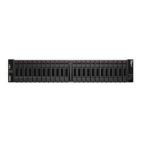
ThinkSystem DS2200
Lenovo ThinkSystem DS2200 Manuals
Manuals and User Guides for Lenovo ThinkSystem DS2200. We have
1
Lenovo ThinkSystem DS2200 manual available for free PDF download: Hardware Installation And Maintenance Manual
Lenovo ThinkSystem DS2200 Hardware Installation And Maintenance Manual (159 pages)
Brand:
Lenovo
| Category:
Storage
| Size: 47.92 MB
Table of Contents
Table of Contents
3
About this Guide
12
Introduction
12
DS6200/DS4200/DS2200 Enclosure User Interfaces
12
CNC Ports Used for Host Connection
13
HD Mini-SAS Ports Used for Host Connection
13
Intended Audience
13
Prerequisites
14
Related Documentation
14
Related Documents
14
Document Conventions and Symbols
15
Document Conventions
15
Safety Guidelines
16
Safe Handling
16
Operation
16
Electrical Safety
17
Power Cooling Module Warning Label - Hazardous Voltage
17
Rack System Safety Precautions
18
Power Cooling Module Warning Label
18
System Overview
20
Enclosure Configurations
20
Cache
20
Compactflash
20
Supercapacitor Pack
20
2U12 Enclosure System - Isometric Front Orientation
22
2U12 Enclosure System - Isometric Rear Orientation
22
2U24 Enclosure System - Isometric Front Orientation
23
2U24 Enclosure System - Isometric Rear Orientation
23
5U84 Enclosure System - Isometric Front and Rear Orientations
24
Enclosure Variants
25
2U12
25
2U24
25
D3284
25
2U Enclosure Core Product
26
2U Enclosure Front Panel
26
2U12 Enclosure System - Front Panel Components
26
2U24 Enclosure System - Front Panel Components
26
2U Enclosure Rear Panel
27
Port Fc/Iscsi Controller Module Detail (DS6200/DS4200)
28
Expansion Module Detail (DS EXP and D3284)
29
Port HD Mini-SAS Controller Module Detail (DS2200 Only)
29
2U Enclosure Chassis
30
Power Cooling Module (PCM) Detail
30
U12 Enclosure Chassis - Isometric Front Orientation
31
5U Enclosure Core Product
32
5U Enclosure Front Panel
33
5U84 Enclosure System - Front Panel Components
33
5U84 Enclosure System - Plan View of Drawer Accessed from Front Panel
33
5U Enclosure Rear Panel
34
Power Supply Unit (PSU) Detail
34
5U Enclosure Chassis
35
5U Enclosure Drawers
35
Fan Cooling Module (FCM) Detail
35
Operator's (Ops) Panel
36
2U Enclosure Ops Panel
36
Enclosure Ops Panel
37
Leds: Ops Panel - 5U Enclosure Front Panel
38
Power Cooling Module - 2U Enclosures
39
580W Pcm
39
Multiple Pcms
39
System Airflow
40
Power Supply Unit - 5U Enclosures
40
Fan Cooling Module - 5U Enclosures
42
Controller and Expansion Modules
43
12Gb/S Controller Module Leds
43
Controller Module - Isometric Rear Orientation
43
Leds:ds6200/Ds4200 Fc/Iscsi Controller Modules (FC and 10Gbe Sfps)
45
Leds: DS6200/DS4200 Iscsi Controller Module (1Gb RJ-45 Sfps)
46
Leds: DS6200/DS4200 SAS Controller Module (HD Mini-SAS)
46
Leds: DS2200 Fc/Iscsi Controller Modules (FC or 10Gbe Sfps)
48
Leds: DS2200 Iscsi Controller Module (1Gb RJ-45 Sfps)
49
Controller Failure When a Single-Controller Is Operational
50
Cache Status LED - Power on Behavior
50
Leds: Rear Panel "Cache Status
51
12Gb/S Expansion Module Leds
52
Disk Drive Module
53
Drive Carrier Module in 2U Chassis
53
Dual Path LFF 3.5" Disk Drive Carrier Modules
54
Drive Status Indicators
55
Dummy Drive Carrier Modules
55
LFF HDD Blank Filler and SFF HDD Blank Filler
55
DDIC in 5U Chassis
56
DDIC with 3.5" Disk
56
Enclosure Management
58
Management Interfaces
58
Installation
59
Installation Checklist
59
Planning for Installation
60
Preparing for Installation
60
Storage System Configuration
60
Preparing the Site and Host Server
61
Unpacking the Enclosure
61
Unpacking the 2U12 and 2U24 Enclosures
62
Required Tools
63
Requirements for Rackmount Installation
63
Rackmount Rail Kit
63
Installing the 2U Enclosure
63
Installing the 5U Enclosure
64
Securing the Brackets to the Rail (Left Hand Rail Shown for 5U)
65
FDE Considerations
66
Connecting the Controller Enclosure and Optional Expansion Enclosures
66
Cable Requirements for Expansion Enclosures
67
Cabling Connections between a 2U Controller Enclosure and 2U Expansion Enclosures
68
Cabling Connections between a 2U Controller Enclosure and D3284 Expansion Enclosure-Reverse
70
Cabling Connections between a 2U Controller Enclosure and D3284 Expansion Enclosure-Straight-Through
70
Power Cord Connection
71
Testing Enclosure Connections
71
Typical AC Power Cord Connection from PDU to PCM (2U)
71
Typical AC Power Cord Connection from PDU to PSU (D3284)
71
Grounding Checks
72
Host System Requirements
72
Cabling Considerations
72
Connecting the Enclosure to Hosts
72
CNC Technology
73
HD Mini-SAS
75
Host Connection
76
Fibre Channel Host Connection
76
10Gbe Iscsi Host Connection
76
1Gb Iscsi Host Connection
76
HD Mini-SAS Host Connection
76
Connecting Hosts: DS6200/DS4200 Direct Attach - One Server/ One HBA/ Dual Path
77
Connecting Hosts: DS2200 Direct Attach - One Server/ One HBA/ Dual Path
77
Connecting Hosts: DS6200/DS4200 Direct Attach - Two Servers/ One HBA Per Server/ Dual Path
77
Connecting Hosts: DS2200 Direct Attach - Two Servers/ One HBA Per Server/ Dual Path
77
Connecting Hosts: DS6200/DS4200 Direct Attach - Four Servers/ One HBA Per Server/ Dual Path
78
Connecting Hosts: DS6200/DS4200 Switch Attach - Two Servers/ Two Switches
78
Connecting Hosts: DS2200 Switch Attach - Two Servers/ Two Switches
78
Connecting a Management Host on the Network
79
Updating Firmware
79
Connecting Hosts: DS6200/DS4200 Switch Attach - Four Servers/ Multiple Switches/ SAN Fabric
79
New User Setup
80
Obtaining IP Values
80
Setting Network Port IP Addresses Using DHCP
80
Setting Network Port IP Addresses Using the CLI Port and Cable
81
Terminal Emulator Display Settings
82
Terminal Emulator Connection Settings
82
Connecting a USB Cable to the CLI Port
82
Configure Controller Network Ports
84
Set Ipv4 Values for Network Ports
85
Set Ipv6 Values for Network Ports
85
Change the CNC Port Mode
86
Connecting Two Storage Systems to Replicate Volumes
86
Cabling for Replication
89
Connecting Two DS6200/DS4200 Storage Systems for Replication: Multiple Servers/One Switch/One Location
89
Connecting Two DS2200 Storage Systems for Replication: Multiple Servers/One Switch/One Location
89
Connecting Two DS6200/DS4200 Storage Systems for Replication: Multiple Servers/Switches/One Location
90
Connecting Two DS2200 Storage Systems for Replication: Multiple Servers/Switches/One Location
90
Connecting Two DS6200/DS4200 Storage Systems for Replication: Multiple Servers/Switches/Two Locations
90
Connecting Two DS2200 Storage Systems for Replication: Multiple Servers/Switches/Two Locations
91
Operation
92
Before You Begin
92
Powering On/Powering off
92
Operator's (Ops) Panel Leds
93
Unit Identification Number
93
Software/Ses
93
Disk Drive Leds
93
Disk Modules Used in 2U Chassis
93
Ddics Used in 5U Chassis
93
Accessing the SMC
94
Configuring and Provisioning the Storage System
94
Troubleshooting and Problem Solving
95
Overview
95
Initial Start-Up Problems
95
Faulty Power Cords
95
Computer Does Not Recognize the Enclosure System
95
Leds
95
2U Enclosure Leds
96
580W PCM Leds
96
Ops Panel Leds
96
PCM LED States
96
Disk Drive Carrier Module Leds
97
IOM Leds
98
Controller Module LED States
98
5U Enclosure Leds
99
Expansion Module LED States
99
PSU Leds
100
Fan Cooling Module Leds
100
Ops Panel Leds
100
PSU LED States
100
Drawer Leds
101
DDIC Led
102
IOM Leds
102
Temperature Sensors
102
Troubleshooting 2U Enclosures
103
PCM Faults
103
Thermal Monitoring and Control
104
Thermal Alarm
104
Troubleshooting 5U Enclosures
105
Thermal Considerations
105
USB CLI Port Connection
105
Fault Isolation Methodology
105
Basic Steps
107
Options Available for Performing Basic Steps
107
Performing Basic Steps
108
If the Enclosure Does Not Initialize
109
Correcting Enclosure Ids
109
Host I/O
109
Dealing with Hardware Faults
109
Isolating a Host-Side Connection Fault
110
Isolating a Controller Module Expansion Port Connection Fault
110
Isolating Replication Faults
110
Continuous Operation During Replacement
110
Firmware Updates
110
Customer-Replaceable Units
111
Crus Addressing 2U 12-Drive Chassis
112
DS4200/DS2200/DS EXP Product Components for 2U 12-Drive Chassis
112
Crus Addressing 2U 24-Drive Chassis
113
DS6200/DS4200/DS2200/DS EXP Product Components for 2U 24-Drive Chassis
113
Crus Addressing High-Density 5U 84-Drive Chassis
114
SBB Ioms Used in DS Series Storage Enclosures
115
Module Removal and Replacement
116
Overview
116
ESD Precautions
116
Preventing Electrostatic Discharge
116
Grounding Methods to Prevent Electrostatic Discharge
116
CRU Replacement for 2U Chassis
117
Replacing a Power Cooling Module
117
Removing a PCM
117
Installing a PCM
120
Replacing a Drive Carrier Module
120
Removing a LFF Drive Carrier Module
121
Removing a LFF Disk Drive Module (1 of 2)
121
Removing a LFF Disk Drive Module (2 of 2)
121
Installing a LFF Drive Carrier Module
122
Installing a LFF Drive Carrier Module (1 of 2)
122
Removing a SFF Drive Carrier Module
123
Installing a LFF Drive Carrier Module (2 of 2)
123
Removing a SFF Disk Drive Module (1 of 2)
124
Removing a SFF Disk Drive Module (2 of 2)
124
Installing a SFF Drive Carrier Module
125
Installing a SFF Drive Carrier Module (1 of 2)
126
Installing a SFF Drive Carrier Module (2 of 2)
126
Replacing a Dummy Drive Carrier
127
Replacing an IOM
127
Before You Begin
127
Configuring Partner Firmware Update
128
Verifying Component Failure
128
Stopping I/O
128
Shutting down a Controller Module
129
Removing an IOM
130
IOM Latch Operation
130
Installing an IOM
131
Removing an IOM
131
Verifying Component Operation
132
CRU Replacement for 5U Chassis
133
Accessing Drawers
133
Opening a Drawer
133
Opening a Drawer (1 of 2)
133
Closing a Drawer
134
Replacing a DDIC
134
Removing a DDIC
134
Opening a Drawer (2 of 2)
134
Removing a DDIC (1 of 2)
135
Installing a DDIC
137
Populating Drawers
137
Preparation
137
Installation Guidelines
138
Replacing a PSU
138
Removing a PSU
138
Installing a PSU
140
Replacing an FCM
140
Removing an FCM
140
Removing an FCM (1 of 2)
141
Installing an FCM
142
Replacing an IOM
142
Removing an IOM
142
IOM Latch Operation Detail
143
Installing an IOM
144
A Technical Specifications
146
Enclosure Dimensions
146
Enclosure Weights
146
Environmental Requirements
147
Power Cooling Module
148
Power Supply Unit
148
B Standards and Regulations
150
International Standards
150
Potential for Radio Frequency Interference
150
European Regulations
150
Safety Compliance
150
EMC Compliance
150
Safety Compliance Specifications
150
AC Power Cords
151
Recycling of Waste Electrical and Electronic Equipment (WEEE)
151
Taiwan BSMI Rohs Declaration
152
CUSB Device Connection
153
Rear Panel USB Ports
153
USB CLI Port
153
Emulated Serial Port
153
USB Device Connection-CLI Port
153
Supported Host Applications
154
Command-Line Interface
154
Device Driver/Special Operation Mode
154
Microsoft Windows
154
Using the CLI Port and Cable-Known Issues on Windows
155
Problem
155
Workaround
155
DSFP Option for CNC Ports
156
Locate the SFP Transceivers
156
Install an SFP Transceiver
156
Install a Qualified SFP Option into an DS4200 or DS6200 Fc/Iscsi Controller Module
156
Verify Component Operation
157
Install a Qualified SFP Option into an DS2200 Fc/Iscsi Controller Module
157
Index
158
Advertisement
Advertisement
Related Products
Lenovo ThinkSystem DS6200
Lenovo D1212
Lenovo ThinkSystem DM3000 series
Lenovo ThinkSystem DM5000 series
Lenovo D1012
Lenovo D1024
Lenovo ThinkSystem DE2000
Lenovo ThinkSystem DE6000
Lenovo ThinkSystem DE2000H 7Y71
Lenovo ThinkSystem DE4000H 7Y74
Lenovo Categories
Laptop
Desktop
Server
Monitor
Tablet
More Lenovo Manuals
Login
Sign In
OR
Sign in with Facebook
Sign in with Google
Upload manual
Upload from disk
Upload from URL