Sign In
Upload
Manuals
Brands
Miele Manuals
Refrigerator
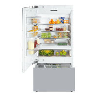
KF 19 Vi Series
Miele KF 19 Vi Series Manuals
Manuals and User Guides for Miele KF 19 Vi Series. We have
1
Miele KF 19 Vi Series manual available for free PDF download: Technical Information
Miele KF 19 Vi Series Technical Information (100 pages)
Brand:
Miele
| Category:
Refrigerator
| Size: 3.32 MB
Table of Contents
Table of Contents
2
Warning and Safety Instructions
8
1 General Information
8
B Modification History
9
C Technical Data
9
Table C-1: General Machine Data
9
Table C-2: Electrical Connection Details
9
Table C-3: Other Machine Data
9
D Layout of Electrical Components
10
1 Appliance Cabinet
10
2 Icemaker
12
Cooling Components
13
1 Technical Data
13
Table 030-1: NTC Resistance Values
13
Table 030-2: Drain Channel Heater Specifications
13
Table 030-3: Defrost Heater Specifications
13
Table 030-4: Other Component Specifications
13
Table 030-5: Other Component Specifications
14
Table 030-6: Other Component Specifications
14
Table 030-7: Compressor Specifications
14
Table 030-8: Temperature Limiter Cutoff
14
Table 030-9: Temperature Limiter Cutoff
14
2 Function
15
Electrical Supply
15
Temperature Sensors (Ntcs)
15
Figure 030-1: NEMA 5-15 Outlet
15
Figure 030-2: Main Power Board with Switch (Sample)
15
Table 030-10: Ntcs
15
Temperature Control
16
Interior Heater (R17/6)
16
Evaporator Fan (M2/4, M2/3)
16
Condenser Fan (M2/1)
16
Table 030-11: Ambient Temperatures and Condenser Fan Speed
16
Refrigerant Stop Valve (Y30/1)
17
Figure 030-3: Condenser Fan and Components (Top View)
17
Starting Program
18
Mastercool Controls
18
Display Icons
18
Figure 030-4: Mastercool Controls
18
Lighting
19
Appliance Status after a Power Interruption
19
Temperature Setting/Desired Temperature Display
19
Table 030-12: Compartment Temperatures
19
Temperature Alarm
20
Door Alarm
20
Door Switches (S4/1, S4/2)
20
Supercool
20
Figure 030-5: Magnetic Actuator on Refrigerator Door Switch
20
Table 030-13: Temperature Alarm Thresholds
20
Superfrost
21
Defrosting
21
Figure 030-6: Defrost Heater and Evaporator (Shown for Refrigerator)
21
Drain Heater, Drain Channel
22
Figure 030-7: Drain Heater and Evaporator Pan
22
Figure 030-8: Drain Channel
22
VCC ® Compressor
23
Figure 030-9: VCC Compressor and Frequency Control Board
23
Table 030-14: Ambient Temperature and Compressor Speed
23
Evaporator
24
Smartfresh Storage
24
Table 030-15: Compressor Speed Versus Frequency
24
Table 030-16: Food Humidity Levels and Air Flap Settings
24
Air Flow
25
Figure 030-10: Closed Air Flaps/High Humidity
25
Figure 030-11: Open Air Flaps/Low Humidity
25
Figure 030-12: Air Flow through the Appliance
26
Figure 030-13: Air Flow into Refrigerator
27
Figure 030-14: Air Flow into Smartfresh Drawers
28
Remotevision
29
Figure 030-15: Air Flow into Freezer
29
3 Fault Repair
30
Vibrations/Compressor Noises
30
High Humidity in Smartfresh Drawers When Dry Food Is Stored
30
Food Has Frozen in Smartfresh Drawers
30
Ice Forms on Interior of Refrigerator, Freezer And/Or Condenser
31
Fault Code Summary
31
Table 030-17: Fault Codes
32
4 Service
33
Customer Settings
33
Table 030-18: Customer Settings
33
Service Programming
34
Service Mode
35
Table 030-19: Service Programming Settings
35
Table 030-20: Service Functions
36
Heater Test
37
Figure 030-16: Test Setup
37
Temperature Test
38
Removing the Refrigerator Evaporator Cover
38
Figure 030-17: Lamp Cover Removal
38
Figure 030-18: Panel Removal
39
Figure 030-19: Glass Plate Removal
39
Removing Refrigerator Air NTC R30/1
40
Figure 030-20: Retaining Screws for the Evaporator Cover Plate
40
Figure 030-21: Retaining Screws for Evaporator Cover, NTC Connection
40
Removing the Refrigerator Lighting Assembly
41
Figure 030-22: NTC R30/1 Removal
41
Figure 030-23: Lighting Assembly Cover and Screws
41
Installing the Refrigerator Lighting Assembly
42
Figure 030-24: Screws Securing the Lighting Assembly Retainers
42
Figure 030-25: Releasing and Removing the Lighting Assembly Retainers
42
Removing the Refrigerator Lighting Assembly Temperature Monitors (1F1, 2F1)
43
Figure 030-26: Lighting Assembly and Retainers
43
Figure 030-27: Inserting the Lighting Assembly
43
Removing the Refrigerator Drain Channel & Defrost Heaters
44
Figure 030-28: Lighting Assembly Temperature Monitor
44
Figure 030-29: Retaining Tabs Holding the Heater Plate
44
Removing Refrigerator Evaporator Temperature Limiter 1F2
45
Figure 030-30: Defrost & Drain Channel Heater Connections
45
Removing Refrigerator Evaporator NTC R30/2
46
Figure 030-31: Temperature Limiter 1F2
46
Removing Refrigerator Evaporator Fan M2/4
47
Figure 030-32: Retainers Holding Evaporator in Place
47
Figure 030-33: Evaporator NTC and Electrical Connection
47
Removing Air Flap Motor M28
48
Removing Air Flap Switch S60/7
48
Figure 030-34: Bottom Fan Retaining Screws
48
Figure 030-35: Evaporator Fan Connection and Top Screws
48
Removing the Smartfresh Compartment Shelf with Control Electronics
49
Figure 030-36: Shelf Release Tabs
49
Figure 030-37: Molex Connections on Shelf
50
Figure 030-38: Underside of Shelf with Control Electronics
50
Air Flap Control Check
51
Refrigerator Door Switch (S4/1) Removal
51
Figure 030-39: Cover Caps and Retaining Screws of Air Flap Housing
51
Figure 030-40: Reed Switch Magnet
51
Removing the Freezer Evaporator Cover
52
Figure 030-41: Reed Switch Removal
52
Figure 030-42: Reed Switch Module
52
Figure 030-43: Evaporator Cover Holders and Retainers
53
Figure 030-44: Evaporator Cover Retaining Screws
53
Removing Freezer Air NTC R30/3
54
Removing the Freezer Lighting Assembly Temperature Monitors (3F1, 4F1)
54
Figure 030-45: Freezer Evaporator Cover Removal
54
Figure 030-46: NTC R30/3 Removal
54
Removing the Freezer Drain Channel & Defrost Heaters (R17/4, R17/2)
55
Figure 030-47: Freezer Lighting Assembly Temperature Monitors
55
Figure 030-48: Heaters and Holder Plate
55
Removing Freezer Evaporator Temperature Limiter 2F2
56
Removing the Freezer Evaporator
56
Figure 030-49: Temperature Limiter 2F2
56
Removing Freezer Evaporator NTC R30/4
57
Figure 030-50: Retainers Holding Evaporator in Place
57
Removing Evaporator Fan M2/3
58
Figure 030-51: Evaporator NTC and Electrical Connection
58
Figure 030-52: Freezer Evaporator Fan Connection and Bottom Screws
58
Removing the Power Electronic/Condenser Fan Assembly
59
Figure 030-53: NTC Connection and Styrofoam Insulation
59
Figure 030-54: Freezer Evaporator Fan Connection and Top Screws
59
Figure 030-55: T20 Screw on Center Wall
60
Figure 030-56: Center Wall Removal
60
Installing the Power Electronic/Condenser Fan Assembly
61
Removing the Power Electronic
61
Figure 030-57: Condenser Fan Connection and Cable Ties
61
Figure 030-58: Seal
61
Removing Condenser Fan M2/1
62
Figure 030-59: Power Electronic Cover
62
Figure 030-60: Power Electronic Holder, Connections, and Protective Foil
62
Installing Condenser Fan M2/1
63
Removing Ambient-Air NTC R30/8
63
Replacing Ambient-Air NTC R30/8
63
Figure 030-61: Condenser Fan M2/1
63
Figure 030-62: Condenser Fan Installation
63
Figure 030-63: Ambient-Air NTC
63
Lighting Transformer (T1) Removal
64
Terminal Block X3/1 Removal
64
Figure 030-64: Transformers
64
Inlet Valve (1Y63, 2Y63) Removal
65
Figure 030-65: Stop Valve Cover
65
Figure 030-66: Terminal Block Cover and Screws
65
VCC Control Voltage Check
66
Removing the VCC Control
66
Figure 030-67: Inlet Valve Connections
66
Figure 030-68: VCC Control Connections
66
Figure 030-69: Terminal Block Retaining Bracket
67
Figure 030-70: Holding Plate
67
Figure 030-71: Screw for Accessing VCC Control Connections
68
Figure 030-72: Screw Securing the VCC Mount
68
Compressor Coil Check
69
Figure 030-73: Three-Pronged Connector and VCC Control
69
Figure 030-74: Three Coils on Compressor
69
VCC Control Testing
70
Compressor Removal
70
Figure 030-75: Compressor Removal, Part 1
71
Figure 030-76: Compressor Removal, Part 2
71
Compressor Installation
72
Installing the Remotevision Module
72
Figure 030-77: Compressor Installation
72
Lightbulb Replacement
73
Figure 030-78: Remotevision Installation, Part 1
73
Figure 030-79: Remotevision Installation, Part 2
73
Figure 030-80: Removing the Light Cover
73
Figure 030-81: Removing and Replacing Lightbulbs
74
Figure 030-82: Side Lighting Cover Removal
74
Figure 030-83: Side Lightbulb Removal
74
Optical Interface (MDU) Position Indication
75
Manually Defrosting the Evaporators
75
Icemaker
76
2 Function
76
Plumbing
76
Water Valves
76
Figure 032-1: Water Valves
76
Figure 032-2: Outlet to Ice Tray
76
Icemaker NTC (R30/21)
77
Ice Cube Production
77
Water Filter
77
Figure 032-3: Optical Sensor
77
3 Fault Repair
78
Icemaker Self-Test
78
Fault Code Summary
79
Table 032-1: Icemaker Fault Codes
81
4 Service
82
Water Filter Replacement
82
Figure 032-4: Water Filter Replacement, Part 1
82
Figure 032-5: Water Filter Replacement, Part 2
82
Icemaker Removal
83
Figure 032-6: Water Filter Replacement, Part 3
83
Figure 032-7: Evaporator NTC and Insulation
84
Figure 032-8: Icemaker Retainer
84
Disconnecting the Water Line
85
Figure 032-9: Icemaker Wiring Harness
85
Figure 032-10: Icemaker Retaining Screws
85
Figure 032-11: Removing the Black Toekick
86
Figure 032-12: Water Connection
86
Figure 032-13: Disconnecting the Water Line
86
Technical Service Bulletins
87
How to Make Sure the Door Switch Is Working
87
Control Electronic on some Cooling Appliances May Randomly Stop Responding
88
Refrigerator Door Reminder
88
How to Replace the Rear Wheels on a Refrigerator
89
Refrigeration Merge Kits: Replacement Cover Strip Is Now Available
92
Mastercool Touch Controls Do Not Respond
92
All about Master Cool and Icemakers
92
F 1471 Dispenser Flap
94
Icemaker Diagnosis Update
94
Advanced Icemaker Troubleshooting
95
Banking Pins Are Now Available for Refrigerators
96
Conversion Kit - Cover for Freezer Door
97
13 Master Cool & Merge Kits
97
14 Master Cool - Filter Light Reset
98
Advertisement
Advertisement
Related Products
Miele KF1911SF
Miele KF1901SF
Miele KF 1911 Vi
Miele Independence KF1901Vi
Miele Independence KF1911SFSS
Miele KF 1901 Vi
Miele KF 1903 SF
Miele KF 1913 SF
Miele KF1913 Vi
Miele KF 1903 Vi
Miele Categories
Washer
Dishwasher
Oven
Ventilation Hood
Dryer
More Miele Manuals
Login
Sign In
OR
Sign in with Facebook
Sign in with Google
Upload manual
Upload from disk
Upload from URL