Sign In
Upload
Manuals
Brands
Mitsubishi Electric Manuals
Controller
CR750 Series
Mitsubishi Electric CR750 Series Manuals
Manuals and User Guides for Mitsubishi Electric CR750 Series. We have
9
Mitsubishi Electric CR750 Series manuals available for free PDF download: Instruction Manual, User Manual, Ethernet Function Instruction Manual, Manual
Mitsubishi Electric CR750 Series Instruction Manual (730 pages)
CR750/CR751/CR760 Series
Brand:
Mitsubishi Electric
| Category:
Controller
| Size: 14 MB
Table of Contents
Table of Contents
13
1 Before Starting Use
21
Using the Instruction Manuals
21
The Details of each Instruction Manuals
21
Symbols Used in Instruction Manual
22
Safety Precautions
23
Precautions Given in the Separate Safety Manual
24
2 Explanation of Functions
26
Operation Panel (O/P) Functions (CR750 Controller)
26
Operation Panel (O/P) Functions (CR760 Controller)
28
Teaching Pendant (T/B) Functions
30
Operation Rights
31
Functions Related to Movement and Control
32
3 Explanation of Operation Methods
34
Operation of the Teaching Pendant Menu Screens
34
Screen Tree
34
Input of the Number/Character
38
Selecting a Menu
39
Jog Feed (Overview)
41
Types of Jog Feed
41
Speed of Jog Feed
42
JOINT Jog
43
XYZ Jog
43
TOOL Jog
44
3-Axis XYZ Jog
44
CYLNDER Jog
45
WORK Jog
45
Switching Tool Data
46
Changing the World Coordinate (Specifies the Base Coordinate Number)
47
Impact Detection During Jog Operation
48
Impact Detection Level Adjustment During Jog Operation
49
Opening/Closing the Hands
50
Returning to the Safe Point
51
Aligning the Hand
52
Programming
54
Creating a Program
54
Opening the Program Edit Screen
54
Creating a Program
55
Completion of Program Creation and Saving Programs
57
Correcting a Program
58
Registering the Current Position Data
60
Deletion of the Position Variable
63
Confirming the Position Data (Position Jump)
64
Correcting the MDI (Manual Data Input)
65
Executing a Command Directly
66
Debugging
67
Step Feed
67
Step Return
68
Step Feed in Another Slot
69
Step Jump
71
Automatic Operation
72
Setting the Operation Speed
72
Operating with the Controller
72
Operating with the T/B
72
Selecting the Program no
72
Starting Automatic Operation
73
Starting by O/P
73
Starting from the T/B
74
Stopping
77
Operating with the Controller
77
Operating with the T/B
77
Resuming Automatic Operation from Stopped State
78
Resuming by O/P
78
Resuming from T/B
78
Resetting the Program
79
Operating with the Controller
79
Operating with the T/B
79
Turning the Servo ON/OFF
80
Error Reset Operation
81
Operation to Temporarily Reset an Error that Cannot be Canceled
81
Operating the Program Control Screen
82
Program List Display
82
Copying Programs
83
Name Change of the Program (Rename)
84
Deleting a Program (Delete)
85
Protection of the Program (Protect)
86
Select the Program
87
Operation of Operating Screen
88
Display of the Execution Line
88
Select the Confirmation Menu
88
Step Feed
88
Step Jump
90
Step Feed in Another Slot
90
Finishing of the Confirmation Screen
91
Test Operation
91
Select the Test Operation
91
Operating the OPERATION Screen
92
Operating the Monitor Screen
93
Input Signal Monitor
93
Output Signal Monitor
95
Input Register Monitor
97
Output Register Monitor
98
Variable Monitor
100
Error History
102
Operation of Parameter Screen
103
Operation of the Origin and the Brake Screen
105
Origin
105
Brake
105
Operation of Setup / Initialization Screen
107
Initialize the Program
107
Initialize the Parameter
108
Initialize the Battery
109
Operation
110
Time Setup
110
Version
111
Enhanced
112
Sq Direct
112
Work Coord
112
Operation of the Initial-Setting Screen
113
Set the Display Language
113
Adjustment of Contrast
115
4 Melfa-Basic V
117
MELFA-BASIC V Functions
117
Robot Operation Control
118
Joint Interpolation Movement
118
Linear Interpolation Movement
119
Circular Interpolation Movement
120
Continuous Movement
122
Acceleration/Deceleration Time and Speed Control
123
Confirming that the Target Position Is Reached
125
High Path Accuracy Control
126
Hand and Tool Control
127
Pallet Operation
128
Program Control
133
Unconditional Branching, Conditional Branching, Waiting
133
Repetition
134
Interrupt
135
Subroutine
136
Timer
137
Stopping
137
Inputting and Outputting External Signals
138
Input Signals
138
Output Signals
138
Communication
139
Expressions and Operations
140
List of Operator
140
Relative Calculation of Position Data (Multiplication)
141
Relative Calculation of Position Data (Addition)
141
Appended Statement
143
The Difference between MELFA-BASIC V and MELFA-BASIC IV
144
Multitask Function
145
What Is Multitasking
145
Executing a Multitask
146
Operation State of each Slot
146
Precautions for Creating Multitask Program
148
How to Perform the Initialization Processing Via Constantly Executed Programs
149
Precautions for Using a Multitask Program
149
Starting the Multitask
149
Display of Operation Status
149
Example of Using Multitask
150
Robot Work Details
150
Procedures to Multitask Execution
151
Program Capacity
152
Program Save Area
152
Program Edit Area
152
Program Execution Area
152
Detailed Specifications of MELFA-BASIC V
153
Program Name
153
Command Statement
153
Variable
154
Statement
155
Appended Statement
155
Step
155
Step no
155
Label
155
Types of Characters that Can be Used in Program
156
Characters Having Special Meanings
157
Uppercase and Lowercase Identification
157
Underscore
157
Apostrophe ( ' )
157
Asterisk ( * )
157
Comma ( , )
157
Period ( . )
157
Space
157
Data Type
158
Constants
158
Numeric Value Constants
158
Decimal Number
158
Hexadecimal Number
158
Binary Number
158
Types of Constant
158
Character String Constants
158
Position Constants
159
Coordinate, Posture and Additional Axis Data Types and Meanings
159
Meaning of Structure Flag Data Type and Meanings
159
Joint Constants
160
Axis Data Format and Meanings
160
Angle Value
161
Variables
161
Numeric Value Variables
162
Character String Variables
162
Position Variables
162
Joint Variables
163
Input/Output Variables
163
Array Variables
163
External Variables
164
Program External Variables
164
User-Defined External Variables
165
Creating User Base Programs
166
Coordinate System Description of the Robot
167
About the Robot's Coordinate System
167
About Base Conversion
168
About Position Data
169
About Tool Coordinate System (Mechanical Interface Coordinate System)
170
Mechanical Interface Coordinate System
170
Tool Coordinate System
171
Effects of Use of Tool Coordinate System
172
Robot Status Variables
175
Logic Numbers
179
Functions
180
User-Defined Functions
180
Built-In Functions
180
List of Command
183
Command Related to Movement Control
183
Command Related to Program Control
184
Definition Commands
184
Multi-Task Related
185
Others
185
Operators
186
Priority Level of Operations
187
Depth of Program's Control Structure
187
Reserved Words
187
Detailed Explanation of Command Words
188
How to Read the Described Items
188
Explanation of each Command Word
188
Detailed Explanation of Robot Status Variable
331
How to Read Described Items
331
Explanation of each Robot Status Variable
331
Detailed Explanation of Functions
417
How to Read Described Items
417
Explanation of each Function
417
Advertisement
Mitsubishi Electric CR750 Series User Manual (468 pages)
Brand:
Mitsubishi Electric
| Category:
Industrial Equipment
| Size: 14.01 MB
Table of Contents
Table of Contents
14
Usage
21
How to Use this Document
21
Checking the Product
21
Checking the Package
21
Checking the CD-ROM Contents
21
About the "Melfarxm.ocx" Communications Middleware
21
Items to be Prepared by the Customer
22
Computer System
22
Computer Cable
22
Operating Environment
23
Connectable Robot Controllers
23
Computer System
24
Installation, Uninstallation
25
Installation
25
Uninstall
31
USB Driver (CR750-D/Crnd-700 Series Robot Controller) Installation
32
Crnq Communications USB Driver Installation
33
Crnq Communications USB Driver for GOT Transparent Function / GOT Communitation Installation
40
When Starting at the same Time as Another Product
42
Upgrade of Software
42
RT Toolbox2 Usage
43
Starting RT Toolbox2
43
Explanation of RT Toolbox2 Screens
44
Communications Server 2
48
About Operation Panel
50
How to Show Operating Panel for a Controller
51
Closing RT Toolbox2
51
Notes of When RT Toolbox2 Is Used with Iq Works (MELSOFT Navigator)
52
Notes of When RT Toolbox2 Is Installed
52
Notes Concerning Workspace Operation
52
Notes Concerning Project Operation
53
Notes to Edit the Workspace Created by Iq Works(MELSOFT Navigator)
54
Basic Functions
55
Workspaces and Projects
57
Creating a New Workspace
59
Opening an Existing Workspace
61
Closing a Workspace
61
Deleting a Workspace
62
Saving a Workspace
62
Changing a Workspace
63
Adding a Project
65
Changing a Project Name
66
Deleting a Project
67
Contents of Project Tree
68
Copying Programs between Projects
69
Import of Project
70
Offline/Online/Simulation
72
Connecting with the Robot
74
Robots Connected and Types of Communication
74
Connection Settings
76
USB Communication Settings
77
TCP/IP (Ethernet) Communication Settings
78
Communication Settings
80
GOT Communications Settings
81
Crnq Communications Settings
82
Travel Base Setting for Display
90
Robot Program Language Setting
93
Writing Programs
94
Writing a New Program
95
Writing a New Program on the Computer
95
Writing a New Program in the Robot Controller
96
Opening an Existing Program
97
Opening an Existing Program on the Computer
97
Opening a Program in a Robot Controller
97
Read Items When Opening Program in Robot Controller
98
Opening a Program in the Backup Data
99
Explanation of Program Edit Screen
100
Program Editing Menu Bar
101
Customizing the Program Edit Screen
103
Changing the Display Area
103
Command Format Hints
104
Character Colors
104
Changing the Font
105
Save and Read of Program
105
Get Current Position
106
Setting the Background Color of the Program Editor
106
Program Editing
108
MELFA-BASIC V Command Statement Editing
108
MELFA-BASIC IV and Movemaster Command Command Statement Editing
109
Position Variable Editing
110
Edit Assist Functions
112
Saving Programs
122
Save
122
Saving on Computer
123
Saving in Robot Controller
124
Items Written When Saving in Robot
125
Setting the Syntax Check for before Program Saving
127
Program Printing
128
Checking a Print Image
128
Printing a Program
128
Setting to Print a Program
128
Program Debugging
129
Starting Debugging
129
Executing Programs Step by Step
130
Revising Programs
130
Setting and Deleting Breakpoints
132
Position Jump
133
Ending Debugging
134
Set / Release Reading Protection
135
Program Management
136
Program List Display
137
Copy
138
Move
139
Delete
140
Rename
141
Protect Settings
141
Comparison
142
Program Conversion
144
Starting Program Conversion
144
Line Number Conversion (from MELFA-BASIC IV to MELFA-BASIC V)
145
Position Data Conversion (from E/EN/M1/M2 Series to CR750/700/500 Series)
147
Position Data Editing for SQ Direct
149
Diffence from Program Editting
150
Add/Edit Position Data
150
Delete Position Data
150
Editing Supporting Function
150
Online Editing
151
Offline Editing
152
Creating the New SQ Direct File
152
Program Management
153
List of SQ Direct Files Indication
154
Creating the Spline Files
156
New File
156
Creating a New File on the Computer
156
Creating a New File in the Robot Controller
156
Open File
157
Opening a Spline File Saved on the Computer
157
Opening a Spline File Saved in the Robot Controller
157
Selecting and Opening a Spline File from the List
157
Save File
158
Save
158
Save as
158
Setting Parameters
159
Editing from Parameter List
160
Starting
160
Parameter Editing
162
Edit of Parameter Changed from Initial Value
163
Parameter List Reading
164
Finding Parameters
164
Robot Controller Operation Modes for Parameter Writing
165
Movement Parameters
166
Motion Limit Parameter
166
Jog Parameter
167
Parameters of the Hand
168
Weight and Size Parameter
170
Tool Parameter
171
User-Defined Area Parameter
172
Free Plane Limit Parameter
173
Home Position Parameter
173
Robot Additional Axis Parameter
174
Collision Detection Parameter
175
Warm-Up Operation Parameter
176
Movement Parameter
177
Work Coordinate Paramater
178
Parameters of Force Control
179
Parameters of Collision Avoidance
184
Parameters of Safety
187
Program Parameters
191
Slot Table Parameter
191
Program Language Parameter
192
Command Parameter
192
User Error Parameter
193
Signal Parameters
194
Output Signal Reset Pattern Parameter
194
Assigning Dedicated Input/Output Signals
195
Communication Parameters
200
Parameter
200
Ethernet Parameter
201
Field Network Parameters
205
CC-Link Parameter
205
PROFIBUS Parameter
206
PROFINET Parameter
207
Devicenet Parameter
208
Ethernet/Ip Parameter
209
PLC Cooperation Parameters
210
Multiple CPU Parameter
210
IO Unit Parameter
211
Parameter Printing
212
Offline Editing of Parameters
214
Compliant Version
214
Creating the New Parameter File
215
Edit of Parameter Backed up
216
Offline Editing of Parameter
217
Restoring the Edited Parameter to the Robot Controller
218
Deletion of Parameter Folder Edited by Offline
220
Status Monitoring
221
Robot Movement Monitoring
222
Slot Operation Status
222
Program Monitoring
223
Movement Status
226
Errors
227
Monitor
232
Signal Monitoring
235
General Signal
235
Named Signals
238
Stop Signal
240
Register (CC-Link)
241
IO Unit Monitor
245
DSI CNUSER2 Input Signal Monitor
246
Operation Monitoring
247
Operating Information
247
Production Information
247
Maintenance
248
Setting Origin Data
248
Origin Data Input Technique
250
Mechanical Stopper Technique
251
Tool Technique
251
ABS Origin Technique
252
User Origin Technique
252
Origin Parameter Backup
253
Initialization
254
Starting
254
Setting the Time in the Robot Controller
254
Deletion of All Robot Programs
255
Initializing the Battery Remaining Time
256
Serial Number
256
Maintenance Forecasting
257
Specifications
257
Starting
257
Forecasting
258
Settings
259
Reset Screen
261
Resetting Maintenance Forecast Information with Teaching Box
263
Others
264
Position Repair Function
265
Specifications
266
Starting
266
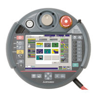
Mitsubishi Electric CR750 Series Instruction Manual (254 pages)
Industrial Robot
Brand:
Mitsubishi Electric
| Category:
Robotics
| Size: 9.62 MB
Table of Contents
Table of Contents
9
1 Before Use
15
The Check of the Package
15
2 Connection with Controller
16
Installing the T/B
16
Removing the T/B
16
3 Specification
17
Specifications
17
Construction
18
4 Basic Operation Method
19
Operating Method of R56TB
19
Selection of Items on Touch Panel
19
Display of Context Menu
19
5 Operation of Menu Panel
20
6 Language Setting
21
7 Guidance
21
RC Time Setting
21
Robot Serial Setting
22
Origin Data Setting
22
8 Setting a Target Robot for Using Multi-Mechanism Control
23
9 JOG Operation
24
Speed Setting
24
Jog Mode
25
Switching Tool Data
26
Switching Base Coordinates
27
JOINT Jog Operation
28
XYZ Jog Operation
29
TOOL Jog Operation
30
3-Axis XYZ Jog Operation
31
Cylinder Jog Operation
32
Work Jog Operation
33
Jog Operation with Wheel
34
Force Control Function
36
Collision Avoidance ON/OFF
37
Aligning the Hand
38
Opening/Closing the Hands
39
Operation of the Electric Hand
40
Operation of the Normal Hand
44
Return to the Home Position
45
10 USB Memory Stick
46
Plug-In the USB Memory Stick
46
Unplug the USB Memory Stick
47
11 Program Edit
48
Edit of Program
48
Open an Edit Display (New Creation)
48
Open an Edit Display (Read of the Existing Program)
50
Save (Robot Controller)
52
Save (USB Memory)
53
Close the Edit Screen
54
Add the Command Line
55
Delete the Command Line
56
Undo the Edited Contents
57
Cut, Copy and Paste
58
Renumber
61
Automatic Numbering
63
Search
64
Replace
66
Jump
68
Editing the Position Variable
70
Registering the Current Position Data
70
Edit of Position Data
72
Addition of Position Data
74
Deletion of Position Data
75
Confirming the Position Data (Position Jump)
76
Find
78
Editiong the Position for SQ Direct Function
79
Registering the Current Position Data for SQ Direct Function
81
Edit of Position Data for SQ Direct Function
82
Addition of Position Data for SQ Direct Function
83
Initialization of Position Data for SQ Direct Function
84
Confirming the Position Data for SQ Direct Function (Position Jump )
84
Saving the Position Data for SQ Direct Function to USB
84
Copy Position Data for SQ Direct Function from Controller to USB
85
Copy Position Data for SQ Direct Function from USB to Controller
86
Edit of Position Data for SQ Direct Function in the USB Memory
87
12 Debugging
88
Starting the Step Operation
88
Step Operation
89
Step Forward
89
Step Backward
89
Continuous Execution
90
Skip
90
Step Forward in Another Slot
91
Step Jump
91
Program Reset
91
Setting and Deleting Breakpoints
92
13 Program Management
93
Starting
93
Program List
95
Copy
96
Move
97
Delete
97
Protect
98
Rename
98
Compare
99
Select Program
101
14 Backup/Restore
102
Starting
102
Backup (Robot -> USB Memory)
103
Restore (USB Memory -> Robot)
104
Power Reset of the Robot Controller
107
15 Monitor
108
Starting
108
Outline of each Function and Starting Methods
109
Outline of each Function
109
Each Monitor Function
110
Robot Movement Monitor
110
Slot Run State
110
Program Monitor
111
Movement State
114
Error
115
Signal Monitor
117
General-Purpose Signal
117
Named Signal
120
Stop Signal
121
Register
122
Operation Monitor
125
Operating Hours
125
Production Information
125
Additional Board Information
126
Servo Monitor
127
Position (ABS)
127
Speed
128
Current
129
Load
131
Power
132
16 Maintenance
133
Origin Data
133
Origin Data Input
134
The Others (Mechanical Stopper, TOOL, ABS, User Origin Method)
135
Initialize
137
Setting the Controller's Date and Time
137
Erase All Programs in the Controller
138
Initialize the Battery Remaining Time
138
Serial Number
139
Serial Number Setting
139
Save Serial Number to File
141
Write Serial Number in a File to the Controller
141
Releasing the Brakes
142
Preparation for Releasing the Brakes
143
Releasing the Brake of One Axis
144
Releasing the Brakes of Two of more Axes
144
Maintenance Forecast
145
Start
145
Forecast (Battery)
145
Forecast (Grease)
146
Forecast (Belt)
147
Gear
148
Setup
149
Reset
151
Others
153
Guidance
154
Security Function of the Robot Controller (Password Setup)
155
Register the Password
156
Change the Password
157
Delete the Password
158
Tool Automtic Calculation
159
Specifications
159
Start
159
Flow of Oerations
160
Advertisement
Mitsubishi Electric CR750 Series Instruction Manual (222 pages)
Industrial Robot, controller, Force Sense Function
Brand:
Mitsubishi Electric
| Category:
Robotics
| Size: 5.77 MB
Table of Contents
Table of Contents
9
1 Using this Manual
14
Terminology Used in this Instruction Manual
14
Select the Force Sensor
15
Using this Manual
16
2 Work Flow
17
Flowchart
17
3 Force Sense Function System Specifications
18
What Is the Force Sense Function
18
System Configuration
19
Force Sensor
19
Attachment
19
Force Sense Function Specifications
20
Force Sense Interface Unit Specifications
22
Force Sense Interface Unit External Dimensions
22
Name of each Force Sense Interface Unit Part
23
Force Sensor Connection Cable
23
VDC Power Supply Specifications
24
VDC Power Supply Outline Drawing
24
VDC Output Cable
25
VDC Input Cable
25
Force Sensor Specifications
26
Force Sensor External Dimensions
27
Sensor Attachment Adapter External Dimensions
28
Coordinate System Definition
30
Force Sense Coordinate System (Mechanical Interface)
31
Force Sense Coordinate System (Tool)
31
Force Sense Coordinate System (XYZ)
32
Force Sensor Coordinate System
33
4 Check before Use
34
Product Check
34
Force Sensor Set 4F-FS001-W200
34
Force Sensor Set 4F-FS001-W1000
35
Software Versions
36
5 Attaching the Force Sensor
37
Attachment Adapter
37
Sensor Installation
37
Recommended Attachment Angle
38
Securing the Force Sensor Cable
39
Tool Installation
40
6 Device Connection, Wiring, and Settings
41
Force Sense Unit ↔ Robot Controller
41
Force Sense Interface Unit ↔ Force Sensor
44
Turning on the Power
46
Warm up Operation
46
Default Parameter Settings
47
Force Sense Interface Unit Identification
48
Calibration
49
Force Sensor Tolerance
52
Force Sensor Control Offset Limit
53
Force Sensor Data Filter Setting
53
Force Sensor Minimum Control Force
53
7 Checking the Connection and Settings
54
Checking Force Sensor Data Communication
54
If Using R56TB/R57TB
54
If Using R32TB/R33TB
55
Checking the Force Sensor Attachment Coordinate System
56
8 Using the Force Sense Function (Programming)
57
Using the Force Sense
57
Force Sense Control
58
Force Sense Enable/Disable Commands
60
Function
60
Using the Force Sense
60
Control Mode / Control Characteristics
61
Offset Cancel Designation
71
Control Characteristics Change Commands
72
Usage Example (Force Sense Control)
74
Force Sense Detection
83
Mo Trigger
84
Force Detection Status
87
Data Latch
87
Data Referencing
87
Usage Example (Force Sense Detection)
88
Force Sense Log
93
Force Sense Log Function Specifications
93
Function (Teaching)
93
Parameter Settings
95
Force Sense Log Data Acquisition
96
Force Sense Log Data Display (RT Toolbox2)
97
Force Sense Log File FTP Transfer
102
Usage Example (Force Sense Log)
103
Gravity Offset Cancel Function
106
Estimated Data
106
About Calibration Posture
106
Calibration Procedure
107
Usage Example (Force Sensor Calibration)
114
Mitsubishi Electric CR750 Series Instruction Manual (159 pages)
Brand:
Mitsubishi Electric
| Category:
Controller
| Size: 3.3 MB
Table of Contents
Table of Contents
9
1 Function and Configuration
13
Overview
13
System Configuration
13
Combination of Software Version
14
Functional Block Diagram
14
Specifications
15
Risk Assessment
16
Residual Risks (Common)
16
Residual Risk (for each Function)
16
2 Installation
18
Confirming the Product
18
Installation and Connection
18
Fixing of the Extended Safety Unit
18
Connecting with the Robot Controller
19
Connecting Cables to the Wiring Connector
20
Connecting the Wiring Connector to the Extended Safety Unit
21
Check Items
21
Long Life Parts
22
Maintenance
22
3 Signals and Wiring
23
Description of Signals
23
Electrical Specifications
23
Signal Operation
24
Connectors and Signal Assignment
25
Input Signal Connection Example
26
Measures against Static Electricity / Noise
27
Safety Monitoring Function Overview
28
Startup
28
Connecting RT Toolbox2
28
Password Setting
28
Enable/Disable
31
Parameter Setting
31
Test Operation
33
Monitoring Mode
34
STO Function
37
SS1 Function
37
SLS Function (Speed Monitoring Function)
38
SLP Function (Position Monitoring Function)
44
STR Function (Torque Monitoring Function)
52
Duplex Input Monitoring Function
55
5 Parameters
56
Safety Monitoring Function Parameters
56
Parameter List
56
Parameter Details
57
CRC Output of the Parameter File
66
6 Troubleshooting
67
List of Errors Related to the Safety Monitoring Function
67
Errors Involving Change in Specification
70
Mitsubishi Electric CR750 Series Ethernet Function Instruction Manual (146 pages)
Electric Industrial Robot
Brand:
Mitsubishi Electric
| Category:
Robotics
| Size: 5.43 MB
Table of Contents
Table of Contents
8
1 Before Use
11
How to Use the Instruction Manual
11
Content of Instruction Manual
11
Terms Used in the Instruction Manual
11
Confirmation of Product
12
Ethernet Function
12
Function of Ethernet
12
2 Preparation before Use
15
Connection of Ethernet Cable
15
Parameter Setting
17
Parameter List
17
Details of Parameters
19
Parameter Setting Example 1 (When the Support Software Is Used)
22
Parameter Setting Example 3 (for Using the Real-Time External Control Function)
25
Connection Confirmation
26
Checking the Connection with the Windows Ping Command
26
3 Description of Functions
27
Controller Communication Function
28
Connecting the Controller and Personal Computer
28
Setting the Personal Computer Network
28
Setting the Controller Parameters
28
Setting the Personal Computer Support Software Communication
29
Communication
30
Data Link Function
31
MELFA-BASIC V/VI Commands
31
Using Data Link Function
35
Ending
38
Real-Time External Control Function
39
Explanation of Command
41
Explanation of Communication Data Packet
43
Using Real-Time External Control Function
47
Ending
49
Real-Time Monitor Function
50
Overview
50
Supported Version
51
Setup
52
Start of Monitor / End of Monitor
54
Explanation of Communication Data Packet
55
Data Type ID
58
Parameters
59
Error
59
SLMP Connection
60
Function Overview
60
Supported Version
60
Specifications
60
Parameters
60
SLMP Communication Procedure
61
Message Format
63
Commands
71
End Code
106
CC-Link IE Field Network Basic Function
107
Overview
107
Supported Version
108
Specifications
108
Parameters
109
Support of Robot I/O Signals and Link Devices
110
Setup Procedure
111
Mitsubishi Electric CR750 Series Instruction Manual (126 pages)
Circular Arc Tracking Function
Brand:
Mitsubishi Electric
| Category:
Controller
| Size: 4.58 MB
Table of Contents
Table of Contents
9
Overview
11
What Is the Circular Arc Tracking Function
11
System that Can Achieve
12
System Configuration
16
Components
16
Robot Controller Enclosure Products
16
Devices Provided by Customers
16
Example of System Configuration
18
Configuration Example of Q Type
18
Configuration Example of D Type
18
Specification
19
Circular Arc Tracking Specifications
19
Q Type
19
D Type
20
Q173Dpx(Manual Pulser Input) Unit Specification
21
Operation Procedure
27
Preparations and Connection of Equipment
28
Connection of Equipment [Q Type]
28
Connection of Unit
28
Connection with Encoder and Encoder Cable
28
Connection of Photoelectronic Sensor
30
Connection of Equipment [D Type]
31
Connection with Encoder and Encoder Cable
31
Installation of Encoder Cable
34
Connection of Photoelectronic Sensor
35
Installation of an Encoder
36
Measures against the Noise
37
Parameter Setting
38
Tracking Parameter Setting
38
Sequencer CPU Parameter Setting [Q Type]
38
Robot Parameter Setting
41
Example of Three Robots' CPU Sharing One Q173DPX [Q Type]
45
Operation Parameters
50
Dedicated Input/Output Parameters
51
Installation of a Sample Robot Program
52
Teaching Operation("A1" Program)
53
Preliminary Preparations
53
Setting of Tool Length
53
Confirm the Encoder Value
54
Knowledge about Work
56
Operation Procedure
57
What to Confirm
65
When Multiple Conveyers and Turntables Are Used
66
Setting of an Operating Condition and Operations Check ("1"Program)
67
Variable for Operating Conditions
67
Automatic Operation
68
Adjustment of the Follow Position
70
Adjustment of Operating Conditions
72
Adjustment of Tracking Starting Possible Area
74
Mitsubishi Electric CR750 Series Instruction Manual (66 pages)
Multifunctional Electric Hand Option
Brand:
Mitsubishi Electric
| Category:
Controller
| Size: 1.5 MB
Table of Contents
Table of Contents
11
1 Using this Manual
13
Content of this Instruction Manual
13
2 Specifications
14
What Is the Electric Hand
14
System Configuration
14
CR800 Outline
14
CR750/CR751 Outline
15
Compatible Models
15
Limitations
16
Available Equipment, Software Version
16
Control Unit
16
Specifications
16
Mehcu-01
16
Mehcu-02
16
Electric Hand
18
Models of Electric Hand
18
Outline Drawing
18
Single Cam Type
18
Screw Type
20
Installing the Fingers
21
Installing Dimensions (Single Cam Type)
21
Installing Dimensions (Screw Type)
22
Specifications of Electric Hand
23
Cam Type
23
Screw Type
24
3-Finger Single Cam Type
25
Hand Cable
26
Models of Hand Cable
26
Outline Drawing
26
Mehcbl-01
26
MEHCBL-02 to 05
26
3 Check before Use
27
Product Checking
27
Items to be Prepared by Customer
28
4 Installation
29
Installation and Connection
29
RV-2F/2FR Series
29
RV-4F/7F/13F/20F Series, RV-4FR/7FR/13FR/20FR Series
30
RH-3FH/6FH/12FH/20FH Series, RH-3FRH/6FRH/12FRH/20FRH Series
32
Rh-3Fhr-S91
33
Maintenance and Inspection
33
Inspection Timings and Items
33
Procedure for Visual Inspection
33
Conducting Operation Check
34
Reapplication of Grease
34
Applicable Grease
34
Applying Grease to the Guide Part
34
Applying Grease to the Ball Screws
35
Applying Grease to the Liner Guide
35
Cleaning Outside of the Gripper
35
Mitsubishi Electric CR750 Series Manual (2 pages)
Industrial Robot, Encoder Distribution Unit
Brand:
Mitsubishi Electric
| Category:
Controller
| Size: 0.4 MB
Advertisement
Related Products
Mitsubishi Electric CR750-D Series
Mitsubishi Electric CR751-D Series
Mitsubishi Electric CR751-Q Series
Mitsubishi Electric CR760-D
Mitsubishi Electric CR750-Q Series
Mitsubishi Electric CR760-Q
Mitsubishi Electric CR751 Series
Mitsubishi Electric CRnQ-700 Series
Mitsubishi Electric CR800-R Series
Mitsubishi Electric CR860-R
Mitsubishi Electric Categories
Air Conditioner
Controller
Projector
Inverter
Heat Pump
More Mitsubishi Electric Manuals
Login
Sign In
OR
Sign in with Facebook
Sign in with Google
Upload manual
Upload from disk
Upload from URL