Sign In
Upload
Manuals
Brands
Mitsubishi Electric Manuals
Inverter
FR-E740 SC ENE
Mitsubishi Electric FR-E740 SC ENE Manuals
Manuals and User Guides for Mitsubishi Electric FR-E740 SC ENE. We have
1
Mitsubishi Electric FR-E740 SC ENE manual available for free PDF download: Instruction Manual
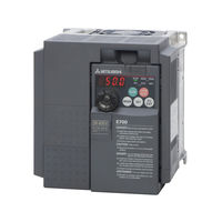
Mitsubishi Electric FR-E740 SC ENE Instruction Manual (608 pages)
Brand:
Mitsubishi Electric
| Category:
Inverter
| Size: 18.33 MB
Table of Contents
Table of Contents
13
1 Product Checking and Part Identification
21
Inverter Type
21
Description of the Case
22
Fr-E700 Sc Ec
22
E700 Sc Ene
23
Accessory
24
2 Installation
25
Removal and Reinstallation of the Front Cover
25
FR-E720S SC and FR-E740-016SC to FR-E740-170SC
25
FR-E740-230SC and FR-E740-300SC
26
Removal and Reinstallation of the Wiring Cover
28
Mounting
29
Enclosure Design
31
Inverter Installation Environment
31
Inverter Placement
35
3 Wiring
37
Inverter and Peripheral Devices
37
Peripheral Devices
39
Terminal Connection Diagram
40
E700 Sc Ec
40
E700 Sc Ene
41
Main Circuit Connection
43
Specification of Main Circuit Terminals
43
Terminal Layout and Wiring
44
Control Circuit Specifications
51
Control Circuit Terminals
54
Wiring Instructions
59
Safety Stop Function
60
Changing the Control Logic
63
PU Connector
66
Connecting the Parameter Unit Using a Connection Cable
66
Connection to the PU Connector at FR-E700 SC ENE
67
RS-485 Communication
67
USB Connector
68
System Configuration for Ethernet Communication (FR-E700 SC ENE)
69
Ethernet Communication Overview
69
Ethernet Connector
70
LED Indicator for Communication Status
71
Removal of the Ethernet Board
72
Connection of Stand-Alone Option Units
73
Magnetic Contactors (MC)
73
Connection of a Dedicated External Brake Resistor FR-ABR (FR-E720S-030SC or More, FR-E740-016SC or More)
75
Connection of a Brake Unit FR-BU2
78
Connection of the High Power Factor Converter FR-HC
81
Connection of the Power Regeneration Common Converter FR-CV
82
Connection of the Power Improving DC Reactor FFR-HEL-(H)-E
83
Installation of a Reactor
83
Electromagnetic Compatibility (EMC)
84
Leakage Currents and Countermeasures
84
Inverter-Generated Noises and Their Reduction Techniques
88
Power Supply Harmonics
91
Inverter-Driven 400 V Class Motor
92
4 Operation
93
Precautions for Use of the Inverter
93
Failsafe of the System Which Uses the Inverter
96
Drive the Motor
99
Operation Panel
100
Parts of the Operation Panel
100
Basic Operation (Factory Setting)
102
Easy Operation Mode Setting (Easy Setting Mode)
103
Operation Lock
105
Monitoring of Output Current and Output Voltage
107
First Priority Monitor
107
Digital Dial Push
107
Change the Parameter Setting Value
108
Parameter Clear/All Parameter Clear
109
Initial Value Change List
110
5 Basic Settings
113
Simple Mode Parameter List
113
Overheat Protection of the Motor by the Inverter
114
When the Rated Motor Frequency Is 60 Hz (Pr. 3)
116
Increase the Starting Torque (Pr. 0)
117
Limit the Maximum and Minimum Output Frequency (Pr. 1, Pr. 2)
119
Change the Acceleration/Deceleration Time (Pr. 7, Pr. 8)
121
Operation Mode (Pr. 79)
123
Large Starting Torque and Low Speed Torque Are Necessary
124
Control) (Pr. 71, Pr. 80, Pr. 81, Pr. 800)
124
To Exhibit the Best Performance of the Motor Performance
127
(Offline Auto Tuning) (Pr. 9, Pr. 71, Pr. 83, Pr. 84, Pr. 96)
127
PU Operation Mode
132
Set the Set Frequency to Operate
133
Use the Digital Dial Like a Potentiometer to Perform Operation
135
Use Switches to Give the Frequency Command (Multi-Speed Setting)
136
Perform Frequency Setting by Analog Voltage Input
138
Perform Frequency Setting by Analog Current Input
140
External Operation
142
Use the Set Frequency Set by PU (Pr. 79 = 3)
142
Use Switches to Give a Start Command and a Frequency Command
144
(Multi-Speed Setting) (Pr. 4 to Pr. 6)
144
Perform Frequency Setting by Analog Voltage Input
147
Perform Frequency Setting by Analog Current Input
151
6 Parameter
155
Parameter Overview
155
Control Mode
186
Change the Control Method (Pr. 80, Pr. 81, Pr. 800)
187
Adjust the Output Torque (Current) of the Motor
189
Manual Torque Boost (Pr. 0, Pr. 46)
189
Advanced Magnetic Flux Vector Control
192
General-Purpose Magnetic Flux Vector Control
195
Slip Compensation (Pr. 245 to Pr. 247)
197
Stall Prevention Operation
198
Limit the Output Frequency
206
Maximum and Minimum Frequency (Pr. 1, Pr. 2, Pr. 18)
206
Avoid Mechanical Resonance Points (Frequency Jumps) (Pr. 31 to Pr. 36)
208
Set V/F Pattern
210
Base Frequency, Voltage (Pr. 3, Pr. 19, Pr. 47)
210
Load Pattern Selection (Pr. 14)
212
Frequency Setting by External Terminals
214
Multi-Speed Setting Operation
214
(Pr. 4 to Pr. 6, Pr. 24 to Pr. 27, Pr. 232 to Pr. 239)
214
Jog Operation (Pr. 15, Pr. 16)
217
Remote Setting Function (Pr. 59)
221
Acceleration and Deceleration
225
Acceleration and Deceleration Time
225
Starting Frequency and Start-Time Hold Function (Pr. 13, Pr. 571)
229
Acceleration and Deceleration Pattern (Pr. 29)
231
Shortest Acceleration/Deceleration (Automatic Acceleration/Deceleration)
233
(Pr. 61 to Pr. 63, Pr. 292, Pr. 293)
233
Selection and Protection of a Motor
236
Motor Overheat Protection (Electronic Thermal O/L Relay) (Pr. 9, Pr. 51)
236
Applied Motor (Pr. 71, Pr. 450)
241
To Exhibit the Best Performance of the Motor Performance (Offline Auto Tuning) (Pr. 71, Pr. 80 to Pr. 84, Pr. 90 to Pr. 94, Pr. 96, Pr. 859)
244
Motor Brake and Stop Operation
254
DC Injection Brake (Pr. 10 to Pr. 12)
254
Selection of a Regenerative Brake (Pr. 30, Pr. 70)
257
Stop Selection (Pr. 250)
259
Stop-On Contact Control Function(Pr. 6, Pr. 48, Pr. 270, Pr. 275, Pr. 276)
261
Brake Sequence Function (Pr. 278 to Pr. 283, Pr. 292)
265
Function Assignment of External Terminals
270
Input Terminal Function Selection (Pr. 178 to Pr. 184)
270
Inverter Output Shutoff Signal (MRS Signal, Pr. 17)
273
Condition Selection of Function Validity by Second Function Selection
275
Signal (RT, Pr. 155)
276
Start Signal Selection (Terminal STF, STR, STOP, Pr. 250)
276
Output Terminal Function Selection (Pr. 190 to Pr. 192/Pr. 313 to Pr. 315)
280
Detection of Output Frequency (SU, FU, Pr. 41 to Pr. 43)
285
Output Current Detection Function (Y12, Y13, Pr. 150 to Pr. 153)
287
Remote Output Function (REM, Pr. 495 to Pr. 497)
289
Monitor Display and Monitor Output Signals
292
Speed Display and Speed Setting (Pr. 37)
292
Monitor Display Selection of DU/PU and Terminal am
294
Reference of the Terminal am (Analog Voltage Output) (Pr. 55, Pr. 56)
302
Terminal am Calibration [Calibration Parameter Pr. 645, C1 (Pr. 901)]
304
Operation Selection at Power Failure
307
Automatic Restart
307
Power Failure-Time Deceleration-To-Stop Function (Pr. 261)
319
Operation Setting at Alarm Occurrence
323
Retry Function (Pr. 65, Pr. 67 to Pr. 69)
323
Input/Output Phase Failure Protection Selection (Pr. 251, Pr. 872)
326
Earth (Ground) Fault Detection at Start (Pr. 249)
327
Energy Saving Operation
328
Optimum Excitation Control (Pr. 60)
328
Motor Noise, EMI Measures, Mechanical Resonance
329
PWM Carrier Frequency and Soft-PWM Control (Pr. 72, Pr. 240)
329
Speed Smoothing Control (Pr. 653)
330
Frequency Setting by Analog Input (Terminal 2, 4)
331
Analog Input Selection (Pr. 73, Pr. 267)
331
Input Filter Time Constant (Pr. 74)
336
Bias and Gain of Frequency Setting Voltage (Current) [Pr. 125, Pr. 126, Pr. 241, C2 (Pr. 902) to C7 (Pr. 905)]
337
Misoperation Prevention and Parameter Setting Restriction
344
Reset Selection/Disconnected PU Detection/Pu Stop Selection (Pr. 75)
344
Parameter Write Selection (Pr. 77)
349
Reverse Rotation Prevention Selection (Pr. 78)
351
User Groups (Pr. 160, Pr. 172 to Pr. 174)
352
Password Function (Pr. 296, Pr. 297)
355
Selection of Operation Mode and Operation Location
360
Operation Mode Selection (Pr. 79)
360
Operation Mode Selection
360
Operation Mode Selection Pr
361
Operation Mode at Power on Pr. 79, Pr
361
External Operation Mode at Power on
364
Fixed to External Operation Mode
369
Operation Mode at Power on (Pr. 79, Pr. 340)
372
Combined Operation Mode
379
External/Pu Combined Operation Mode
379
Communication Operation (Pr. 338, Pr. 339, Pr. 550, Pr. 551)
383
Communication Operation and Setting
383
PU Connector
383
Initial Settings and Specifications of RS-485 Communication
388
Communication E²PROM Write Selection (Pr. 342)
399
Mitsubishi Inverter Protocol (Computer Link Communication)
400
Modbus®-RTU Communication
419
Initial Settings and Specifications of Ethernet Communication
437
MELSOFT / FA Product Connection (FR-E700 SC ENE)
445
USB Communication (Pr. 547, Pr. 548)
446
Special Operation
447
PID Control (Pr. 127 to Pr. 134)
447
Dancer Control (Pr. 44, Pr. 45, Pr. 128 to Pr. 134)
459
Droop Control (Pr. 286 to Pr. 287)
467
Regeneration Avoidance Function
468
Useful Functions
471
Cooling Fan Operation Selection (Pr. 244)
471
Display of the Life of the Inverter Parts (Pr. 255 to Pr. 259)
472
Maintenance Timer Alarm (Pr. 503, Pr. 504)
477
Current Average Value Monitor Signal (Pr. 555 to Pr. 557)
478
Free Parameters (Pr. 888, Pr. 889)
482
Setting for the Parameter Unit, Operation Panel
483
RUN Key Rotation Direction Selection (Pr. 40)
483
PU Display Language Selection (Pr. 145)
483
Operation Panel Frequency Setting/Key Lock Operation Selection (Pr. 161)
484
Magnitude of Frequency Change Setting (Pr. 295)
485
Buzzer Control (Pr. 990)
486
PU Contrast Adjustment (Pr. 991)
486
Modbus®/Tcp (Fr-E700 Sc Ene)
487
CC-Link IE Field Network Basic
503
Programming Examples
518
Instructions
527
7 Troubleshooting
529
List of Alarm Display
530
Causes and Corrective Actions
532
Reset Method of Protective Function
547
LED Display
548
Check and Clear of the Fault History
549
Check First When You Have Troubles
551
Motor Does Not Start
551
Motor or Machine Generates Abnormal Noise
553
Inverter Generates Abnormal Noise
553
Motor Generates Heat Abnormally
553
Motor Rotates in Opposite Direction
554
Acceleration/Deceleration Is Not Smooth
554
Speed Varies During Operation
555
Operation Mode Is Not Changed Properly
556
Motor Current Is too Large
556
Speed Does Not Accelerate
557
Unable to Write Parameter Setting
557
Meters and Measuring Methods
558
Measurement of Powers
559
Measurement of Voltages and Use of PT
560
Measurement of Currents
560
Use of CT and Transducer
561
Measurement of Inverter Input Power Factor
561
Measurement of Converter Output Voltage (Across Terminals P/+ and N/-)
561
8 Maintenance and Inspection
563
Daily Inspection
563
Periodic Inspection
563
Daily and Periodic Inspection
564
Display of the Life of the Inverter Parts
566
Checking the Inverter and Converter Modules
567
Cleaning
568
Replacement of Parts
568
Inverter Replacement
572
Measurements on the Main Circuit
573
Insulation Resistance Test Using Megger
573
Pressure Test
573
Measurement of Voltages and Currents
574
A Appendix
577
Specifications
577
1-Phase, 200 V Class
577
3-Phase, 400 V Class
578
Common Specifications
579
Outline Dimension Drawings
581
FR-E720S-008SC-EC to 030SC-EC
581
FR-E720S-050SC-EC and 080SC-EC
582
FR-E720S-110SC-EC and FR-E740-016SC-EC to 095SC-EC
583
FR-E740-120SC-EC and 170SC-EC
584
FR-E740-230SC-EC and 300SC-EC
584
FR-E720S-008SC-ENE to 030SC-ENE
585
Fr-E720S-050Sc-Ene, 080Sc-Ene
586
E720S-110SC-ENE FR-E740-016SC-ENE to 095SC-ENE
587
Fr-E740-120Sc-Ene, 170Sc-Ene
588
Fr-E740-230Sc-Ene, 300Sc-Ene
589
Parameter Unit FR-PU07
590
Parameter Unit FR-PA07
591
Parameter List with Instruction Codes
592
Specification Change
602
SERIAL Number Check
602
Advertisement
Advertisement
Related Products
Mitsubishi Electric FR-E740 SC EC Series
Mitsubishi Electric FR-E740-7.5K(SC)
Mitsubishi Electric FR-E740-5.5K
Mitsubishi Electric FR-E740-040
Mitsubishi Electric FR-E740-060
Mitsubishi Electric FR-E740-0.4KNF
Mitsubishi Electric FR-E740-0.75K
Mitsubishi Electric FR-E740-3.7KNC
Mitsubishi Electric FR-E740-7.5KNC
Mitsubishi Electric FR-E740 EC
Mitsubishi Electric Categories
Air Conditioner
Controller
Projector
Inverter
Heat Pump
More Mitsubishi Electric Manuals
Login
Sign In
OR
Sign in with Facebook
Sign in with Google
Upload manual
Upload from disk
Upload from URL