Sign In
Upload
Manuals
Brands
Mitsubishi Electric Manuals
Inverter
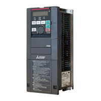
FR-F820-03160
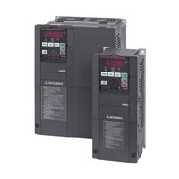
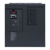
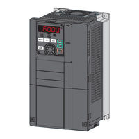
Mitsubishi Electric FR-F820-03160 Manuals
Manuals and User Guides for Mitsubishi Electric FR-F820-03160. We have
7
Mitsubishi Electric FR-F820-03160 manuals available for free PDF download: Instruction Manual, Installation Manuallines
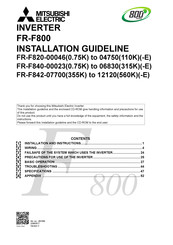
Mitsubishi Electric FR-F820-03160 Instruction Manual (940 pages)
FR-F800 series
Brand:
Mitsubishi Electric
| Category:
Inverter
| Size: 21.65 MB
Table of Contents
Instruction Manual
1
Safety Instructions
5
Table of Contents
13
1 Introduction
21
General Remarks
21
Product Checking and Accessories
23
Inverter Model
23
Accessory
24
How to Read the SERIAL Number
24
Component Names
25
Operation Steps
27
Related Manuals
28
2 Installation and Wiring
29
Peripheral Devices
29
Inverter and Peripheral Devices
29
Peripheral Devices
32
Removal and Reinstallation of the Operation Panel or the Front Covers
40
Installation of the Inverter and Enclosure Design
45
Inverter Installation Environment
45
Cooling System Types for Inverter Enclosure
48
Inverter Installation
49
Panel through Attachment Procedure
51
Terminal Connection Diagrams
53
CA Type
53
FM Type
55
CA Type (FR-F800-E)
57
FM Type (FR-F800-E)
59
Main Circuit Terminals
61
Details on the Main Circuit Terminals
61
Terminal Layout of the Main Circuit Terminals, Wiring of Power Supply
62
And the Motor
62
Applicable Cables and the Wiring Length
65
Earthing (Grounding) Precautions
72
Control Circuit
74
Details on the Control Circuit Terminals
74
Control Logic (Sink/Source) Change
78
Wiring of Control Circuit
81
Wiring Precautions
85
When Using Separate Power Supplies for the Control Circuit
86
When Supplying 24 V External Power to the Control Circuit
89
Safety Stop Function
92
Communication Connectors and Terminals
95
PU Connector
95
USB Connector
96
Terminal Block (Not for FR-F800-E)
98
Connection of Stand-Alone Option Units
99
Connection of the Brake Unit (FR-BU2)
99
Connection of the Brake Unit (FR-BU)
102
Connection of the Brake Unit (BU Type)
103
Connection of the High Power Factor Converter (FR-HC2)
104
Connection of the Power Regeneration Common Converter (FR-CV)
106
Connection of the Power Regeneration Converter (MT-RC)
107
Connection of the DC Reactor (FR-HEL)
108
Installing a Communication Option (FR-F800-E)
109
System Configuration for Ethernet Communication (FR-F800-E)
110
Ethernet Communication Overview
110
Ethernet Connector
111
Removal of the Ethernet Board
113
3 Precautions for Use of the Inverter
115
Electro-Magnetic Interference (EMI) and Leakage Currents
115
Leakage Currents and Countermeasures
115
Countermeasures against Inverter-Generated EMI
120
Built-In EMC Filter
123
Power Supply Harmonics
125
Harmonic Suppression Guidelines
126
Installation of a Reactor
130
Power-OFF and Magnetic Contactor (MC)
131
Countermeasures against Deterioration of the 400 V Class Motor Insulation
133
Checklist before Starting Operation
134
Failsafe System Which Uses the Inverter
137
4 Basic Operation
141
Operation Panel (FR-DU08)
141
Components of the Operation Panel (FR-DU08)
141
Basic Operation of the Operation Panel
143
Correspondences between Digital and Actual Characters
145
Changing the Parameter Setting Value
146
Monitoring the Inverter Status
147
Monitoring of Output Current and Output Voltage
147
First Monitored Item
147
Displaying the Set Frequency
148
Easy Operation Mode Setting (Easy Setting Mode)
149
Frequently-Used Parameters (Simple Mode Parameters)
151
Simple Mode Parameter List
151
Basic Operation Procedure (PU Operation)
153
Operating at the Set Frequency (Example: Operating at 30 Hz)
153
Using the Setting Dial Like a Potentiometer to Perform Operation
155
Setting the Frequency by Switches (Multi-Speed Setting)
156
Setting the Frequency with Analog Signals (Voltage Input)
158
Using an Analog Signal (Current Input) to Give a Frequency Command
160
Basic Operation Procedure (External Operation)
162
Using the Frequency Set by the Operation Panel
162
Setting the Frequency by Switches (Multi-Speed Setting) (Pr. 4 to Pr. 6)
164
Setting the Frequency with Analog Signals (Voltage Input)
166
Changing the Frequency (60 Hz, Initial Value) at the Maximum Voltage Input
167
(5 V, Initial Value)
167
Using an Analog Signal (Current Input) to Give a Frequency Command
168
Changing the Frequency (60 Hz, Initial Value) at the Maximum Current Input
169
(At 20 Ma, Initial Value)
169
Basic Operation Procedure (JOG Operation)
170
Performing JOG Operation Using External Signals
170
JOG Operation from the Operation Panel
171
5 Parameters
173
Parameter List
174
Parameter List (by Number)
174
Group Parameter Display
198
Parameter List (by Function Group)
200
Control Method
211
Changing the Control Method
213
Selecting the Advanced Magnetic Flux Vector Control
217
Selecting the PM Motor Control
220
Speed Control under PM Motor Control
225
Setting Procedure of PM Motor Control
226
Performing High-Accuracy, Fast-Response Control
227
Troubleshooting in the Speed Control
230
Torque Detection Filter
231
E) Environment Setting Parameters
232
Real Time Clock Function
233
Reset Selection/Disconnected PU Detection/Pu Stop Selection
235
PU Display Language Selection
239
Buzzer Control
239
PU Contrast Adjustment
239
Display-Off Mode
240
Resetting USB Host Errors
240
Setting Dial Potentiometer Mode/Key Lock Operation Selection
241
Frequency Change Increment Amount Setting
242
Multiple Rating Setting
243
Using the Power Supply Exceeding 480 V
244
Parameter Write Selection
244
Password Function
248
Free Parameter
252
Setting Multiple Parameters as a Batch
252
Extended Parameter Display and User Group Function
257
PWM Carrier Frequency and Soft-PWM Control
260
Inverter Parts Life Display
263
Maintenance Timer Alarm
267
Current Average Value Monitor Signal
269
F) Setting of Acceleration/Deceleration Time and Acceleration/Deceleration Pattern
273
Setting the Acceleration and Deceleration Time
274
Acceleration/Deceleration Pattern
279
Remote Setting Function
283
Starting Frequency and Start-Time Hold Function
287
Minimum Motor Speed Frequency
289
D) Operation Command and Frequency Command
290
Operation Mode Selection
291
Operation Mode
293
Startup in Network Operation Mode at Power-ON
300
During Communication Operation
302
Reverse Rotation Prevention Selection
311
Frequency Setting Via Pulse Train Input
312
JOG Operation
316
Operation by Multi-Speed Setting
318
H) Protective Function Parameter
321
Motor Overheat Protection (Electronic Thermal O/L Relay)
322
Cooling Fan Operation Selection
332
Earth (Ground) Fault Detection at Start
333
Varying the Activation Level of the Undervoltage Protective Function
333
Initiating a Protective Function
334
I/O Phase Loss Protection Selection
335
Retry Function
336
Emergency Drive (Fire Mode)
339
Limiting the Output Frequency (Maximum/Minimum Frequency)
348
Avoiding the Mechanical Resonance Points (Frequency Jump)
350
Stall Prevention Operation
352
Load Characteristics Fault Detection
361
Motor Overspeeding Detection
366
M) Monitor Display and Monitor Output Signal
367
Speed Display and Rotations Per Minute Setting
368
Monitor Indicator Selection Using Operation Panel or Via Communication
370
Monitor Display Selection for Terminals FM/CA and am
383
Adjusting Terminals FM/CA and am
390
Energy Saving Monitor
396
Output Terminal Function Selection
403
Output Frequency Detection
412
Output Current Detection Function
416
Output Torque Detection
418
Remote Output Function
419
Analog Remote Output Function
421
Fault Code Output Selection
424
Pulse Train Output of Output Power
425
Detection of Control Circuit Temperature
426
T) Multi-Function Input Terminal Parameters
427
Analog Input Selection
427
Analog Input Terminal (Terminal 1, 4) Function Assignment
432
Analog Input Compensation
433
Analog Input Responsiveness and Noise Elimination
436
Frequency Setting Voltage (Current) Bias and Gain
438
Bias and Gain for Voltage (Current) Setting of Stall Prevention Operation Level
445
Checking of Current Input on Analog Input Terminal
452
Input Terminal Function Selection
457
Inverter Output Shutoff Signal
461
Selecting Operation Condition of the Second Function Selection Signal (RT)
463
Start Signal Operation Selection
465
C) Motor Constant Parameters
469
Applied Motor
469
Offline Auto Tuning
475
Offline Auto Tuning for a PM Motor (Motor Constants Tuning)
488
Online Auto Tuning
499
A) Application Parameters
504
Electronic Bypass Function
505
Self Power Management
514
Traverse Function
518
Cleaning Function
520
PID Control
525
PID Gain Tuning
545
Changing the Display Increment of Numerical Values Used in PID Control
553
PID Pre-Charge Function
557
Multi-Pump Function (Advanced PID Function)
564
PID Control Enhanced Functions
576
Automatic Restart after Instantaneous Power Failure
587
Flying Start with an Induction Motor
587
Automatic Restart after Instantaneous Power Failure
595
Flying Start with an IPM Motor
595
Offline Auto Tuning for a Frequency Search
598
Power Failure Time Deceleration-To-Stop Function
604
PLC Function
611
Trace Function
615
N) Operation Via Communication and Its Settings
624
Wiring and Configuration of PU Connector
625
Wiring and Configuration of RS-485 Terminals
627
Initial Setting of Operation Via Communication
631
Initial Settings and Specifications of RS-485 Communication
639
Mitsubishi Inverter Protocol (Computer Link Communication)
641
Error Code
647
MODBUS® RTU Communication Specification
660
Bacnet MS/TP Protocol
678
Alarm History
690
Initial Settings and Specifications of Ethernet Communication (FR-F800-E)
694
MELSOFT / FA Product Connection
702
USB Device Communication
703
Automatic Connection with GOT
704
G) Control Parameters
706
Manual Torque Boost
707
Base Frequency, Voltage
709
Load Pattern Selection
711
Energy Saving Control
713
Adjustable 5 Points V/F
714
SF-PR Slip Amount Adjustment Mode
716
DC Injection Brake
717
Output Stop Function
720
Stop Selection
722
Regenerative Brake Selection and DC Feeding Mode
724
Regeneration Avoidance Function
732
Increased Magnetic Excitation Deceleration
736
Slip Compensation
738
Speed Smoothing Control
739
Parameter Clear / All Parameter Clear
740
Copying and Verifying Parameters on the Operation Panel
742
Parameter Copy
743
Parameter Verification
744
Copying and Verifying Parameters Using USB Memory
745
Checking Parameters Changed from Their Initial Values (Initial Value Change List)
749
Ethernet Communication (FR-F800-E)
750
Slmp
750
Communication Procedure
751
Modbus®/Tcp
765
CC-Link IE Field Network Basic (FR-F800-E)
782
Programming Examples
797
Instructions
806
Inverter-To-Inverter Link Function (FR-F800-E)
807
6 Protective Functions
813
Inverter Fault and Alarm Indications
813
Reset Method for the Protective Functions
814
Check and Clear of the Faults History
815
Check for the Faults History
815
Faults History Clearing Procedure
816
The List of Fault Displays
817
Causes and Corrective Actions
821
Error Message
821
Warning
825
Alarm
829
Fault
830
Other Messages
844
Check First When You Have a Trouble
845
Motor Does Not Start
845
Motor or Machine Is Making Abnormal Acoustic Noise
848
Inverter Generates Abnormal Noise
849
Motor Generates Heat Abnormally
849
Motor Rotates in the Opposite Direction
849
Speed Greatly Differs from the Setting
850
Acceleration/Deceleration Is Not Smooth
850
Speed Varies During Operation
851
Operation Mode Is Not Changed Properly
852
Operation Panel (FR-DU08) Display Is Not Operating
852
Motor Current Is too Large
852
Speed Does Not Accelerate
853
Unable to Write Parameter Setting
854
Power Lamp Is Not Lit
854
7 Precautions for Maintenance and Inspection
855
Inspection Item
855
Daily Inspection
855
Periodic Inspection
855
Daily and Periodic Inspection
856
Checking the Inverter and Converter Modules
858
Cleaning
859
Replacement of Parts
859
Inverter Replacement
865
Measurement of Main Circuit Voltages, Currents and Powers
866
Measurement of Powers
869
Measurement of Voltages and Use of PT
870
Measurement of Currents
871
Use of CT and Transducer
872
Measurement of Inverter Input Power Factor
872
Measurement of Converter Output Voltage (Across Terminals P and N)
872
Measurement of Inverter Output Frequency
872
Insulation Resistance Test Using Megger
873
Pressure Test
873
8 Specifications
875
Inverter Rating
875
V Class
876
Motor Rating
878
Premium High-Efficiency IPM Motor [MM-EFS (1500 R/Min Specification)]
878
Premium High-Efficiency IPM Motor [MM-EFS (3000 R/Min Specification)]
880
Premium High-Efficiency IPM Motor [MM-THE4 (1500 R/Min Specification)]
882
Common Specifications
884
Outline Dimension Drawings
886
Inverter Outline Dimension Drawings
886
Dedicated Motor Outline Dimension Drawings
895
Advertisement
Mitsubishi Electric FR-F820-03160 Instruction Manual (834 pages)
Brand:
Mitsubishi Electric
| Category:
Inverter
| Size: 21.11 MB
Table of Contents
Table of Contents
13
Introduction
21
General Remarks
21
Product Checking and Accessories
22
Inverter Model
22
Accessory
23
How to Read the SERIAL Number
23
Component Names
24
Operation Steps
26
Related Manuals
27
Installation and Wiring
29
Peripheral Devices
29
Inverter and Peripheral Devices
29
Peripheral Devices
32
Removal and Reinstallation of the Operation Panel or the Front Covers
40
Installation of the Inverter and Enclosure Design
45
Inverter Installation Environment
45
Cooling System Types for Inverter Enclosure
48
Inverter Installation
49
Panel through Attachment Procedure
51
Terminal Connection Diagrams
53
FM Type
53
CA Type
55
Main Circuit Terminals
57
Details on the Main Circuit Terminals
57
Terminal Layout of the Main Circuit Terminals, Wiring of Power Supply
58
Applicable Cables and the Wiring Length
61
Earthing (Grounding) Precautions
68
Control Circuit
70
Details on the Control Circuit Terminals
70
Control Logic (Sink/Source) Change
74
Wiring of Control Circuit
77
Wiring Precautions
81
When Using Separate Power Supplies for the Control Circuit
82
When Supplying 24 V External Power to the Control Circuit
85
Safety Stop Function
88
Communication Connectors and Terminals
90
PU Connector
90
USB Connector
91
RS-485 Terminal Block
93
Connection of Stand-Alone Option Units
94
Connection of the Brake Unit (FR-BU2)
94
Connection of the Brake Unit (FR-BU)
97
Connection of the Brake Unit (BU Type)
98
Connection of the High Power Factor Converter (FR-HC2)
99
Connection of the Power Regeneration Common Converter (FR-CV)
101
Connection of the Power Regeneration Converter (MT-RC)
102
Connection of the DC Reactor (FR-HEL)
103
Precautions for Use of the Inverter
105
Electro-Magnetic Interference (EMI) and Leakage Currents
105
Leakage Currents and Countermeasures
105
Countermeasures against Inverter-Generated EMI
110
Built-In EMC Filter
113
Power Supply Harmonics
115
Harmonic Suppression Guidelines
116
Installation of a Reactor
120
Power-OFF and Magnetic Contactor (MC)
121
Countermeasures against Deterioration of the 400 V Class Motor Insulation
123
Checklist before Starting Operation
124
Failsafe System Which Uses the Inverter
127
Basic Operation
131
Operation Panel (FR-DU08)
131
Components of the Operation Panel (FR-DU08)
131
Basic Operation of the Operation Panel
133
Correspondences between Digital and Actual Characters
135
Changing the Parameter Setting Value
136
Monitoring the Inverter Status
137
Monitoring of Output Current and Output Voltage
137
First Monitored Item
137
Displaying the Set Frequency
138
Easy Operation Mode Setting (Easy Setting Mode)
139
Frequently-Used Parameters (Simple Mode Parameters)
141
Simple Mode Parameter List
141
Basic Operation Procedure (PU Operation)
143
Operating at the Set Frequency (Example: Operating at 30 Hz)
143
Using the Setting Dial Like a Potentiometer to Perform Operation
145
Setting the Frequency by Switches (Multi-Speed Setting)
146
Setting the Frequency with Analog Signals (Voltage Input)
148
Using an Analog Signal (Current Input) to Give a Frequency Command
150
Basic Operation Procedure (External Operation)
152
Using the Frequency Set by the Operation Panel
152
Setting the Frequency by Switches (Multi-Speed Setting) (Pr. 4 to Pr. 6)
154
Setting the Frequency with Analog Signals (Voltage Input)
156
Changing the Frequency (60 Hz, Initial Value) at the Maximum Voltage Input
157
(5 V, Initial Value)
157
Using an Analog Signal (Current Input) to Give a Frequency Command
158
Changing the Frequency (60 Hz, Initial Value) at the Maximum Current Input
159
(At 20 Ma, Initial Value)
159
Basic Operation Procedure (JOG Operation)
160
Performing JOG Operation Using External Signals
160
JOG Operation from the Operation Panel
161
Parameters
163
Parameter List
164
Parameter List (by Number)
164
Group Parameter Display
186
Parameter List (by Function Group)
188
Control Method
198
Changing the Control Method
200
Selecting the Advanced Magnetic Flux Vector Control
204
Selecting the PM Motor Control
207
Speed Control under PM Motor Control
212
Setting Procedure of PM Motor Control
213
Performing High-Accuracy, Fast-Response Control
214
Troubleshooting in the Speed Control
217
Torque Detection Filter
218
E) Environment Setting Parameters
219
Real Time Clock Function
220
Reset Selection/Disconnected PU Detection/Pu Stop Selection
222
PU Display Language Selection
226
Buzzer Control
226
PU Contrast Adjustment
226
Display-Off Mode
227
Resetting USB Host Errors
227
Setting Dial Potentiometer Mode/Key Lock Operation Selection
228
Frequency Change Increment Amount Setting
229
Multiple Rating Setting
230
Using the Power Supply Exceeding 480 V
231
Parameter Write Selection
231
Password Function
235
Free Parameter
239
Setting Multiple Parameters as a Batch
239
Extended Parameter Display and User Group Function
244
PWM Carrier Frequency and Soft-PWM Control
247
Inverter Parts Life Display
250
Maintenance Timer Alarm
254
Current Average Value Monitor Signal
256
F) Setting of Acceleration/Deceleration Time and Acceleration/Deceleration Pattern
261
Setting the Acceleration and Deceleration Time
261
Acceleration/Deceleration Pattern
266
Remote Setting Function
270
Starting Frequency and Start-Time Hold Function
274
Minimum Motor Speed Frequency
276
D) Operation Command and Frequency Command
277
Operation Mode Selection
278
Startup in Network Operation Mode at Power-ON
287
Reverse Rotation Prevention Selection
296
Frequency Setting Via Pulse Train Input
297
JOG Operation
301
Operation by Multi-Speed Setting
303
H) Protective Function Parameter
306
Motor Overheat Protection (Electronic Thermal O/L Relay)
307
Cooling Fan Operation Selection
317
Earth (Ground) Fault Detection at Start
318
Varying the Activation Level of the Undervoltage Protective Function
318
Initiating a Protective Function
319
I/O Phase Loss Protection Selection
320
Retry Function
321
Emergency Drive (Fire Mode)
324
Limiting the Output Frequency (Maximum/Minimum Frequency)
333
Avoiding the Mechanical Resonance Points (Frequency Jump)
335
Stall Prevention Operation
337
Load Characteristics Fault Detection
346
Motor Overspeeding Detection
351
M) Monitor Display and Monitor Output Signal
352
Speed Display and Rotations Per Minute Setting
353
Monitor Indicator Selection Using Operation Panel or Via Communication
355
Monitor Display Selection for Terminals FM/CA and am
368
Adjusting Terminals FM/CA and am
375
Energy Saving Monitor
381
Output Terminal Function Selection
388
Output Frequency Detection
396
Output Current Detection Function
400
Output Torque Detection
402
Remote Output Function
403
Analog Remote Output Function
405
Fault Code Output Selection
408
Pulse Train Output of Output Power
409
Detection of Control Circuit Temperature
410
T) Multi-Function Input Terminal Parameters
416
Analog Input Terminal (Terminal 1, 4) Function Assignment
416
Analog Input Compensation
417
Analog Input Responsiveness and Noise Elimination
420
Frequency Setting Voltage (Current) Bias and Gain
422
Bias and Gain for Voltage (Current) Setting of Stall Prevention Operation Level
429
Checking of Current Input on Analog Input Terminal
436
Input Terminal Function Selection
441
Inverter Output Shutoff Signal
445
Selecting Operation Condition of the Second Function Selection Signal (RT)
447
Start Signal Operation Selection
449
C) Motor Constant Parameters
453
Applied Motor
453
Offline Auto Tuning
453
Offline Auto Tuning for a PM Motor (Motor Constants Tuning)
472
Online Auto Tuning
483
A) Application Parameters
488
Electronic Bypass Function
489
Self Power Management
498
Traverse Function
502
Cleaning Function
504
PID Control
509
PID Gain Tuning
529
Changing the Display Increment of Numerical Values Used in PID Control
537
PID Pre-Charge Function
541
Multi-Pump Function (Advanced PID Function)
548
PID Control Enhanced Functions
560
Automatic Restart after Instantaneous Power Failure
571
Automatic Restart after Instantaneous Power Failure
579
Offline Auto Tuning for a Frequency Search
582
Power Failure Time Deceleration-To-Stop Function
588
PLC Function
595
Trace Function
599
N) Operation Via Communication and Its Settings
608
Wiring and Configuration of PU Connector
608
Wiring and Configuration of RS-485 Terminals
610
Initial Setting of Operation Via Communication
614
Initial Settings and Specifications of RS-485 Communication
618
Mitsubishi Inverter Protocol (Computer Link Communication)
620
MODBUS RTU Communication Specification
639
Bacnet MS/TP Protocol
657
USB Device Communication
673
Automatic Connection with GOT
674
G) Control Parameters
676
Manual Torque Boost
677
Base Frequency, Voltage
679
Load Pattern Selection
681
Energy Saving Control
683
Adjustable 5 Points V/F
684
SF-PR Slip Amount Adjustment Mode
686
DC Injection Brake
687
Output Stop Function
690
Stop Selection
692
Regenerative Brake Selection and DC Feeding Mode
694
Regeneration Avoidance Function
702
Increased Magnetic Excitation Deceleration
706
Slip Compensation
708
Speed Smoothing Control
708
Parameter Clear / All Parameter Clear
710
Copying and Verifying Parameters on the Operation Panel
712
Parameter Copy
713
Parameter Verification
714
Copying and Verifying Parameters Using USB Memory
715
Checking Parameters Changed from Their Initial Values (Initial Value Change List)
719
Protective Functions
721
Inverter Fault and Alarm Indications
721
Reset Method for the Protective Functions
722
Check and Clear of the Faults History
723
Check for the Faults History
723
Faults History Clearing Procedure
724
The List of Fault Displays
725
Causes and Corrective Actions
729
Error Message
729
Warning
733
Alarm
736
Fault
737
Check First When You Have a Trouble
751
Motor Does Not Start
751
Motor or Machine Is Making Abnormal Acoustic Noise
754
Inverter Generates Abnormal Noise
755
Motor Generates Heat Abnormally
755
Motor Rotates in the Opposite Direction
755
Speed Greatly Differs from the Setting
756
Acceleration/Deceleration Is Not Smooth
756
Speed Varies During Operation
757
Operation Mode Is Not Changed Properly
758
Operation Panel (FR-DU08) Display Is Not Operating
758
Motor Current Is too Large
758
Speed Does Not Accelerate
759
Unable to Write Parameter Setting
760
Power Lamp Is Not Lit
760
Precautions for Maintenance and Inspection
761
Inspection Item
761
Daily Inspection
761
Periodic Inspection
761
Daily and Periodic Inspection
762
Checking the Inverter and Converter Modules
764
Cleaning
765
Replacement of Parts
765
Inverter Replacement
771
Measurement of Main Circuit Voltages, Currents and Powers
772
Measurement of Powers
775
Measurement of Voltages and Use of PT
776
Measurement of Currents
777
Use of CT and Transducer
778
Measurement of Inverter Input Power Factor
778
Measurement of Converter Output Voltage (Across Terminals P and N)
778
Measurement of Inverter Output Frequency
778
Insulation Resistance Test Using Megger
779
Pressure Test
779
Specifications
781
Inverter Rating
781
Class
781
Motor Rating
784
Premium High-Efficiency IPM Motor [MM-EFS (1500 R/Min Specification)]
784
Premium High-Efficiency IPM Motor [MM-EFS (3000 R/Min Specification)]
786
Premium High-Efficiency IPM Motor [MM-THE4 (1500 R/Min Specification)]
788
Mitsubishi Electric FR-F820-03160 Instruction Manual (660 pages)
FR-F800 series
Brand:
Mitsubishi Electric
| Category:
Inverter
| Size: 16.46 MB
Table of Contents
Inverter Fr-F800 Instruction Manual (Detailed)
2
Table of Contents
2
Safety Instructions
9
Fire Prevention
10
Chapter 1 Introduction
16
Product Checking and Accessories
18
Serial Number
19
Component Names
20
Operation Steps
22
About the Related Manuals
23
Chapter 2 Installation and Wiring
24
Peripheral Devices
25
Peripheral Devices
27
Removal and Reinstallation of the Operation Panel or the Front Covers
31
Installation of the Inverter and Enclosure Design
35
Amount of Heat Generated by the Inverter
38
Cooling System Types for Inverter Enclosure
39
Inverter Installation
40
Protruding the Heat Sink through a Panel
42
Terminal Connection Diagrams
44
Main Circuit
46
Control Circuit
46
Main Circuit Terminals
48
Main Circuit Terminal Layout and Wiring to Power Supply and Motor
49
Applicable Cables and Wiring Length
51
Earthing (Grounding) Precautions
58
Control Circuit
59
Control Logic (Sink/Source) Change
63
Wiring of Control Circuit
64
Wiring Precautions
67
When Supplying 24 V External Power to the Control Circuit
70
Safety Stop Function
71
Communication Connectors and Terminals
74
USB Connector
75
RS-485 Terminal Block
76
Connection of Stand-Alone Option Units
77
Connection of the Brake Unit (FR-BU)
79
Connection of the High Power Factor Converter (FR-HC2)
80
Connection of the Power Regeneration Common Converter (FR-CV)
81
Connection of the Power Regeneration Converter (MT-RC)
82
Chapter 3 Precautions for Use of the Inverter 4 5
84
Electro-Magnetic Interference (EMI) and Leakage Currents
85
Techniques and Measures for Electromagnetic Compatibility (EMC)
87
Built-In EMC Filter
89
Power Supply Harmonics
92
Installation of a Reactor
96
Power Shutdown and Magnetic Contactor (MC)
97
Countermeasures against Deterioration of the 400 V Class Motor Insulation
99
Checklist before Starting Operation
100
Failsafe System Which Uses the Inverter
103
Chapter 4 Basic Operation
106
Operation Panel (FR-DU08)
107
Basic Operation of the Operation Panel
109
Digital Characters and Their Corresponding Printed Equivalents
110
Changing the Parameter Setting Value
111
Monitoring the Inverter
112
Easy Setting of the Inverter Operation Mode
113
Frequently-Used Parameters (Simple Mode Parameters)
115
Basic Operation Procedure (PU Operation)
117
Perform PU Operation Using the Setting Dial Like a Potentiometer
118
Setting the Frequency with Switches (Multi-Speed Setting)
119
Setting the Frequency Using an Analog Signal (Voltage Input)
120
Setting the Frequency Using an Analog Signal (Current Input)
121
Basic Operation Procedure (External Operation)
123
Setting the Frequency and Giving a Start Command with Switches (Multi-Speed Setting) (Pr.4 to Pr.6)
124
Setting the Frequency Using an Analog Signal (Voltage Input)
125
Changing the Frequency (60 Hz, Initial Value) at the Maximum Voltage Input (5 V, Initial Value)
127
Setting the Frequency Using an Analog Signal (Current Input)
128
Changing the Frequency (60 Hz, Initial Value) at the Maximum Current Input (at 20 Ma, Initial Value)
129
Basic Operation Procedure (JOG Operation)
130
Giving a Start Command from the Operation Panel for JOG Operation
131
Chapter 5 Parameters
132
Parameter List
133
Use of a Function Group Number for the Identification of Parameters
157
Parameter List (by Function Group Number)
159
Control Method
168
Changing the Control Method and Mode
170
Selecting the Advanced Magnetic Flux Vector Control
173
Selecting the PM Motor Control
175
Speed Control under PM Motor Control
181
Performing High-Accuracy, Fast-Response Control (Gain Adjustment for PM Motor Control)
183
Troubleshooting in the Speed Control
185
Torque Detection Filter
186
E) Environment Setting Parameters
187
Real Time Clock Function
188
Reset Selection / Disconnected PU Detection / PU Stop Selection
189
PU Display Language Selection
192
Direct Setting
193
Frequency Change Increment Amount Setting
194
Multiple Rating Setting
195
Using the Power Supply Exceeding 480 VAC
196
Parameter Write Selection
197
Password
199
Free Parameter
201
Extended Parameter Display and User Group Function
205
PWM Carrier Frequency and Soft-PWM Control
208
Inverter Parts Life Display
209
Maintenance Timer Alarm
213
Current Average Value Monitor Signal
214
F) Setting of Acceleration/Deceleration Time and Acceleration/Deceleration Pattern
217
Control Block Diagram
218
Acceleration/Deceleration Pattern
220
Remote Setting Function
223
Starting Frequency and Start-Time Hold Function
226
Minimum Motor Speed Frequency at the Motor Start up
227
D) Operation Command and Frequency Command
229
Startup of the Inverter in Network Operation Mode at Power-ON
238
Start Command Source and Frequency Command Source During Communication Operation
240
Reverse Rotation Prevention Selection
246
JOG Operation
249
Operation by Multi-Speed Setting
250
H) Protective Function Parameter
253
Cooling Fan Operation Selection
259
Earth (Ground) Fault Detection at Start
260
Varying the Activation Level of the Undervoltage Protective Function
261
Retry Function
262
Emergency Drive
264
Limiting the Output Frequency (Maximum/Minimum Frequency)
272
Avoiding Machine Resonance Points (Frequency Jump)
273
Stall Prevention Operation
274
Load Characteristics Fault Detection
282
Motor Overspeeding Detection
286
M) Item and Output Signal for Monitoring
287
Monitor Item Selection on Operation Panel or Via Communication
289
Monitor Display Selection for Terminals FM/CA and am
298
Adjustment of Terminal FM/CA and Terminal am
303
Energy Saving Monitoring
307
Output Terminal Function Selection
313
Output Signal List
314
Output Frequency Detection
320
Output Current Detection Function
322
Output Torque Detection Function
324
Remote Output Function
325
Analog Remote Output Function
326
Fault Code Output Selection
328
Pulse Train Output to Announce Cumulative Output Energy
329
Detection of Control Circuit Temperature
330
T) Multi-Function Input Terminal Parameters
331
Analog Input Terminal (Terminal 1, 4) Function Assignment
335
Analog Input Compensation
336
Response Level of Analog Input and Noise Elimination
338
Frequency Setting Voltage (Current) Bias and Gain
340
Bias and Gain for Voltage (Current) Setting of Stall Prevention Operation Level
345
Checking of Current Input on Analog Input Terminal
351
Input Terminal Function Selection
356
Inverter Output Shutoff
358
Selecting the Condition to Activate the Second Function Selection (RT) Signal
359
Start Signal Operation Selection
360
(C) Motor Constant Parameters
363
Offline Auto Tuning
367
Offline Auto Tuning for a PM Motor (Motor Constant Tuning)
376
Online Auto Tuning
383
A) Application Parameters
387
Electronic Bypass Function
388
Self Power Management
394
Start Count Monitor
396
Traverse Function
397
Cleaning Function
399
PID Control
402
PID Gain Tuning
418
Changing the Display Increment of Numerical Values Used in PID Control
424
PID Pre-Charge Function
426
Multi-Pump Function (Advanced PID Function)
431
PID Control Enhanced Functions
440
Automatic Restart after Instantaneous Power Failure/Flying Start with an Induction Motor
447
Automatic Restart after Instantaneous Power Failure/Flying Start with a PM Motor
452
Offline Auto Tuning for a Frequency Search
455
Power Failure Time Deceleration-To-Stop Function
459
PLC Function
463
Trace Function
466
N) Communication Operation Parameters
474
Wiring and Configuration of RS-485 Terminals
476
Initial Setting of Operation Via Communication
479
Initial Settings and Specifications of RS-485 Communication
483
Mitsubishi Inverter Protocol (Computer Link Communication)
485
Setting Items and Set Data
494
MODBUS RTU Communication Specification
499
Message Format
500
Function Code List
502
Bacnet MS/TP Protocol
512
USB Device Communication
524
Backup/Restore
526
(G) Control Parameters
528
Base Frequency Voltage
529
Load Pattern Selection
531
Excitation Current Low-Speed Scaling Factor
532
Energy Saving Control
533
Adjustable 5 Points V/F
534
SF-PR Slip Amount Adjustment Mode
535
DC Injection Brake
536
Output Stop Function
537
Stop Selection
539
Regenerative Brake Selection and DC Feeding Mode
540
Regeneration Avoidance Function
546
Increased Magnetic Excitation Deceleration
548
Slip Compensation
549
Speed Smoothing Control
550
Parameter Clear / All Parameter Clear
552
5.15 Copying and Verifying Parameters on the Operation Panel
553
Parameter Verification
555
Copying and Verifying Parameters Using a USB Memory
556
Checking Parameters Changed from Their Initial Values (Initial Value Change List)
560
Chapter 6 PROTECTIVE FUNCTIONS
563
Reset Method for the Protective Functions
564
Check and Clear of the Fault History
565
List of Fault Displays
567
Causes and Corrective Actions
569
Check First When You Have a Trouble
586
Motor or Machine Is Making Abnormal Acoustic Noise
589
Motor Rotates in the Opposite Direction
590
Speed Varies During Operation
591
Operation Panel (FR-DU08) Display Is Not Operating
592
Speed Does Not Accelerate
593
Power Lamp Is Not Lit
594
Chapter 7 PRECAUTIONS for MAINTENANCE and
597
Inspection
597
Daily and Periodic Inspection
598
Checking the Inverter and Converter Modules
599
Cleaning
600
Removal and Reinstallation of the Control Circuit Terminal Block
606
Measurement of Main Circuit Voltages, Currents, and Powers
607
Measurement of Powers
609
Use of CT and Transducer
610
Insulation Resistance Test Using Megger
611
Chapter 8 SPECIFICATIONS
613
Inverter Rating
613
Motor Rating
616
Premium High-Efficiency IPM Motor [MM-EFS (3000 R/Min Specification)]
618
Premium High-Efficiency IPM Motor [MM-THE4]
619
Common Specifications
621
Outline Dimension Drawings
623
Dedicated Motor Outline Dimension Drawings
631
Chapter 9 APPENDIX
635
For Customers Replacing the Conventional Model with this Inverter
635
Replacement of the FR-F500(L) Series
636
Parameters (Functions) and Instruction Codes under Different Control Methods
639
For Customers Using HMS Network Options
655
Advertisement
Mitsubishi Electric FR-F820-03160 Instruction Manual (91 pages)
Brand:
Mitsubishi Electric
| Category:
Inverter
| Size: 7.65 MB
Table of Contents
Inverter Model
3
Inverter Placement
3
Installation Environment
3
Outline Dimensions
4
Terminal Connection Diagrams
5
Main Circuit Terminals
7
Terminal Layout
11
Control Circuit Terminal
11
Wiring Method
11
Wiring Precautions
12
Control Logic (Sink/Source) Change
12
When Supplying 24 V External Power to the Control Circuit
12
Safety Stop Function
13
Function Description
13
Connection Diagram
13
Failsafe System Which Uses the Inverter
14
Precautions for Use of the Inverter
15
Drive the Motor
16
Components of the Operation Panel (FR-DU08)
16
Basic Operation (Factory Setting)
17
Parameter List
18
Troubleshooting
23
Reset Method for the Protective Functions
23
List of Fault Displays
24
Specifications
25
Appendix 1 Instructions for Compliance with the EU Directives
27
EMC Directive
27
Appendix 2 Instructions for UL and Cul
29
General Precaution
29
Installation
29
Motor Overload Protection
30
PID Control Enhanced Functions
37
Mitsubishi Electric FR-F820-03160 Instruction Manual (88 pages)
Brand:
Mitsubishi Electric
| Category:
Air Conditioner
| Size: 8.08 MB
Table of Contents
Table of Contents
30
Inverter Installation and Precautions
32
Wiring
33
Basic Operation
38
Failsafe System Which Uses the Inverter
40
Precautions for Use of the Inverter
40
Mitsubishi Electric FR-F820-03160 Installation Manuallines (64 pages)
FR-F800 series
Brand:
Mitsubishi Electric
| Category:
Inverter
| Size: 3.91 MB
Table of Contents
Table of Contents
1
Fire Prevention
3
Installation and Instructions
7
Installation of the Inverter
8
Wiring
10
Terminal Layout and Wiring
18
Control Circuit Terminals
25
Terminal Layout
25
Wiring Method
25
Wiring Precautions
26
Connection Diagram
28
Function Description
28
Failsafe of the System Which Uses the Inverter
30
Precautions for Use of the Inverter
31
Basic Operation
33
Parameter List
35
Troubleshooting
50
Reset Method of Protective Function
51
List of Alarm Display
51
Specifications
53
Outline Dimensions
56
Appendix
58
Aappendix
58
Mitsubishi Electric FR-F820-03160 Installation Manuallines (64 pages)
Brand:
Mitsubishi Electric
| Category:
Inverter
| Size: 3.89 MB
Table of Contents
Table of Contents
1
Installation and Instructions
7
Wiring
10
Failsafe of the System Which Uses the Inverter
30
Precautions for Use of the Inverter
31
Basic Operation
33
Troubleshooting
50
Specifications
53
Aappendix
58
Advertisement
Related Products
Mitsubishi Electric FR-F820-03800
Mitsubishi Electric FR-F820-00105
Mitsubishi Electric FR-F820-00490
Mitsubishi Electric FR-F820-00630
Mitsubishi Electric FR-F820-00770
Mitsubishi Electric FR-F820-00930
Mitsubishi Electric FR-F820-01250
Mitsubishi Electric FR-F820-01870
Mitsubishi Electric FR-F820-02330
Mitsubishi Electric FR-F820-04750
Mitsubishi Electric Categories
Air Conditioner
Controller
Projector
Inverter
Heat Pump
More Mitsubishi Electric Manuals
Login
Sign In
OR
Sign in with Facebook
Sign in with Google
Upload manual
Upload from disk
Upload from URL