Sign In
Upload
Manuals
Brands
Mitsubishi Electric Manuals
Video Game Controller
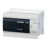
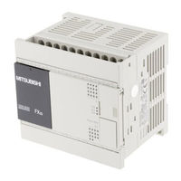
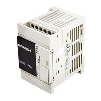
FX3S-10M series
Mitsubishi Electric FX3S-10M series Manuals
Manuals and User Guides for Mitsubishi Electric FX3S-10M series. We have
9
Mitsubishi Electric FX3S-10M series manuals available for free PDF download: User Manual, Structured Programming Manual, Beginners Manual, Quick Start Manual, Hardware Manual
Mitsubishi Electric FX3S-10M series User Manual (532 pages)
Brand:
Mitsubishi Electric
| Category:
Video Game Controller
| Size: 7.86 MB
Table of Contents
Table of Contents
9
Safety Precautions
3
Table of Contents
9
H. Fx -3A-Adp
19
Introduction
27
Common Items
27
Outline and Features of Analog Control
27
Analog Input Control
28
Analog Output Control
29
Temperature Sensor Input Control
30
Description of Analog Products
31
Types of Analog Products
31
Expansion Board
31
Special Adapter
32
List of Analog Product Models
37
Special Function Block
38
List of Analog Product Models
38
System Configuration Drawings of Analog Products
41
Fx 3S
41
Connection of Expansion Boards, Special Adapters
42
Fx 3G
42
System Configuration Drawings of Analog Products a
43
Connection of Special Function Blocks
44
FX 3G Series PLC
44
FX 3GC Series PLC
45
Connection of Special Adapters
45
Connection of Special Function Blocks
46
FX 3U Series PLC
47
Connection of Special Adapters
47
Connection of Special Function Blocks
48
FX 3UC Series PLC
49
Connection of Special Adapters
49
Connection of Special Function Blocks
51
Comparison of Performance Specifications
53
Analog Input
53
Fx 3U -4Ad-Adp
53
Fx 2N -2Ad
54
Fx 3U -4Ad
55
Fx 2N -4Ad
56
Fx 3Uc -4Ad
57
Fx 2Nc -4Ad
58
Fx 2N -8Ad
59
Fx 3G -2Ad-Bd
60
Analog Output
61
Fx 3U -4Da-Adp
61
Fx 2N -2Da
62
Fx 3U -4Da
63
Fx 2N -4Da
64
Fx 2Nc -4Da
65
Fx 3G -1Da-Bd
66
Mixed Analog Input/Output
67
Fx 3U -3A-Adp
67
Fx 2N -5A
68
Fx 0N -3A
70
Temperature Sensor Input
71
Fx -4Ad-Pt-Adp
71
Fx 3U -4Ad-Ptw-Adp
72
Fx 3U -4Ad-Pnk-Adp
73
Fx 3U -4Ad-Tc-Adp
74
Fx 2N -4Ad-Pt
75
Fx 2N -4Ad-Tc
76
Fx 2N -8Ad
77
Fx 2N -2Lc
78
Fx 3U -4Lc
79
Version Number
80
PLC Main Unit
80
Manufacturer's Serial Number Check Method
80
Version Check
81
Special Adapter
82
Manufacturer's Serial Number Check Method
82
Manual Introduction (Types, Contents, and Obtainment
83
How to Use the Manuals
83
Description of Related Manuals
84
Analog Control Manuals
84
Manuals Related to the FX /FX /FX 3GC /FX /FX 3UC Series PLC Main Unit
84
Manuals of Analog Units
86
Generic Names and Abbreviations in this Manual
88
FX -4AD (4-Channel Analog Input) FX 3UC -4AD (4-Channel Analog Input)
91
Outline
93
Outline of Functions
93
Setup Procedure before Starting Operation
94
Compatible Programming Tool Version Number
95
Connectable PLC and Version Numbers
95
Specifications
96
Generic Specifications
96
Power Supply Specifications
97
Performance Specifications
97
Input Mode (Characteristics) BFM#0
98
Wiring
99
Terminal Layout
100
Cable and Terminal Tightening Torque
101
Cable (FX 3U -4AD
101
Power Cable (FX 3UC -4AD
101
Cable (FX 3UC -4AD
102
Examples of Power Supply Circuit
103
Fx -4Ad
103
Cautions Regarding Connection of Power Cables
104
Fx -4Ad
104
Fx 3Uc -4Ad
104
Analog Input Line
105
Grounding
106
Analog Input
107
Analog Input Procedures
107
Buffer Memory (BFM
109
Assignment of Unit Numbers and Outline of Buffer Memory
109
Buffer Memory Reading/Writing Method
111
Buffer Memory Direct Specification (FX 3U /FX 3UC PLC Only
111
FROM/TO Instruction (FX 3G /FX 3GC /FX 3U /FX 3UC PLC
111
Buffer Memory List (BFM)
112
Buffer Memory List (BFM
113
Buffer Memory Details
116
BFM#0: Input Mode Specification
116
BFM#2 to #5: Averaging Time
117
BFM#6 to #9: Digital Filter Setting
118
BFM#10 to #13: Channel Data
119
BFM#19: Data Change Disable
120
BFM#20: Initialization Function (Resetting to Factory Default Status
120
BFM#21: Input Characteristics Writing
120
BFM#22: Convenient Function Setting
121
BFM#26: Upper/Lower Limit Error Status
123
BFM#27: Abrupt Change Detection Status
124
BFM#28: Over-Scale Status
125
BFM#29: Error Status
126
BFM#30: Model Code
127
BFM#41 to #44: Offset Data / BFM#51 to #54: Gain Data
127
BFM#61 to #64: Addition Data
128
BFM#71 to #74: Lower Limit Error Setting / BFM#81 to #84: Upper Limit Error Setting
129
BFM#91 to #94: Abrupt Change Detection Value Setting
130
BFM#101 to #104: Minimum Peak Value / BFM#111 to #114: Maximum Peak Value
131
BFM#99: Clearance of Upper/Lower Limit Error Data and Abrupt Change Detection Data
131
BFM#109: Minimum Peak Value Resetting / BFM#119: Maximum Peak Value Resetting
132
BFM#125: Peak Value Automatic Transfer to First Data Register Specification
132
BFM#126: Upper/Lower Error Status Data Automatic Transfer-To Data Register Specification
133
BFM#127: Abrupt Change Detection Status Data Automatic Transfer-To Data Register Specification
134
BFM#128: Over-Scale Status Data Automatic Transfer-To Data Register Specification
135
BFM#129: Error Status Data Automatic Transfer-To Data Register Specification
135
BFM#197: Selection of Cyclic Data Update Function (Function for Data History
136
BFM#198: Data History Sampling Time Setting
136
BFM#199: Data History Resetting/Stoppage
137
BFM#200 to #6999: Data History
138
Changing Input Characteristics
139
Procedure for Changing Input Characteristics
139
Examples of Practical Programs
142
Program that Uses Averaging Time
142
Program that Uses Convenient Functions
144
Program that Uses Data History Function
147
Initialization Program for 4AD (Factory Default
150
Troubleshooting
151
PLC Version Number Check
151
Wiring Check
151
Program Check
151
Error Status Check
152
4AD Initialization and Test Program
153
Outline
157
Outline of Functions
157
FX 3U -4AD-ADP (4-Channel Analog Input)
158
Outline
158
Setup Procedure before Starting Operation
158
Connectable Plcs and Version Number
159
Compatible Programming Tool Version Number
160
Specifications
161
Generic Specifications
161
Power Supply Specifications
162
Performance Specifications
162
A/D Conversion Time
162
A/D Conversion Time
163
When Connected to a FX 3G /FX 3GC PLC
163
When Connected to a FX 3S PLC
163
When Connected to a FX PLC
163
When Connected to a FX /FX 3GC PLC
164
When Connected to a FX /FX 3UC PLC
164
When Connected to a FX /FX 3UC PLC
165
Wiring
166
Terminal Layout
167
Applicable Cables and Terminal Tightening Torque
168
Power Supply Line
169
To Connect to the FX /FX /FX Series PLC
169
To Connect to the FX 3GC /FX 3UC Series PLC
169
Analog Input Line
170
Grounding
170
Programming
171
Loading of A/D Conversion Data
171
List of Special Devices
172
Switching of Input Mode
174
Input Data
175
Averaging Time
176
Error Status
177
Model Code
179
Basic Program Example
180
Basic Program Example
181
Changing of Input Characteristics
182
Example: Changing of Voltage Input Characteristics
182
Troubleshooting
185
PLC Version Number Check
185
Wiring Check
185
Special Device Check
186
Program Check
186
Error Status Check
186
Error Status Check
187
FX -2AD-BD (2-Channel Analog Input)
189
Outline
191
Outline of Functions
191
Setup Procedure before Starting Operation
193
Connectable Plcs and Version Number
194
Compatible Programming Tool Version Number
194
Specifications
195
Generic Specifications
195
Performance Specifications
196
A/D Conversion Time
197
For FX 3G Series PLC
198
For FX Series PLC
198
Wiring
199
Terminal Layout
200
Applicable Cables and Terminal Tightening Torque
201
Analog Input Line
202
Loading of A/D Conversion Data
203
Programming
203
List of Special Devices
204
Input Data
205
Switching of Input Mode
205
Averaging Time
206
Error Status
207
Model Code
209
Changing of Input Characteristics
210
Troubleshooting
211
Program Check
212
Outline
217
Setup Procedure before Starting Operation
218
Connectable Plcs and Version Number
219
Specifications
220
Power Supply Specifications
221
Performance Specifications
221
Output Mode (Characteristics) BFM#0
222
Wiring
223
Terminal Layout
224
Wiring to Power Supply Terminals
225
Analog Output Wiring
226
Analog Output
227
Buffer Memory (BFM)
229
Buffer Memory Reading/Writing Method
231
Plc
231
Buffer Memory List (BFM)
232
Buffer Memory Details
235
BFM#1 to #4: Output Data
236
BFM#6: Output Status
237
BFM#9: Offset/Gain Setting Value Write Command
238
BFM#10 to #13: Offset Data/Bfm#14 to #17: Gain Data
239
BFM#19: Data Change Prohibition of Setting Change
240
BFM#20: Initialization Function (Resetting to Factory Default Status)
241
BFM#29: Error Status
242
BFM#30: Model Code
243
BFM#38: Upper/Lower Limit Function Setting
244
BFM#39: Upper/Lower Limit Function Status
245
BFM#41 to #44: Lower Limit Values of Upper/Lower Limit Function BFM#45 to #48: Upper Limit Values of Upper/Lower Limit Function
246
Only in Voltage Output Mode)/Bfm#51 to #54: Load Resistance Values
247
BFM#60: Status Automatic Transfer Function Setting
248
BFM#61: Error Status Data Automatic Transfer-To Data Register Specification
249
BFM#62: Upper/Lower Limit Function Status Data Automatic Transfer-To Data Register Specification
250
BFM#63: Specification of Data Register for Automatic Transfer at Disconnection Detection
251
Table Output Function
252
Preparation of Data Table
253
Procedures for Transferring Data Table to Buffer Memory
258
Procedures for Executing Table Output Function
262
Details of Table Output Error
264
Examples Uses of Table Output Function
266
Changing Output Characteristics
267
Examples of Practical Programs
270
Example of Program Using Useful Functions
271
Example of Program for Table Output Operation (Pattern Output Operation)
274
Program to Initialize FX 3U -4DA (Factory Default)
277
Troubleshooting
278
Error Status Check
279
FX 3U -4DA Initialization and Test Program
280
Outline of Function
283
Setup Procedure before Starting Operation
284
Connectable Plcs and Version Number
285
Compatible Programming Tool Version Number
286
When Connected to a FX 3G /FX 3GC PLC
286
Specifications
287
Power Supply Specifications
288
D/A Conversion Time
289
When Connected to a FX /FX 3UC PLC
291
Wiring
292
Terminal Layout
293
Applicable Cables and Terminal Tightening Torque
294
Power Supply Line
295
To Connect to the FX /FX /FX Series PLC
295
To Connect to the FX 3GC /FX 3UC Series PLC
295
Grounding
296
Analog Output Line
296
Programming
297
List of Special Devices
299
Switching of Output Mode
301
Output Holding Function Cancellation Setting
302
Output Setting Data
303
Error Status
304
Basic Program Example
306
Model Code
306
Changing of Output Characteristics
307
Troubleshooting
309
Program Check
310
Outline
315
Setup Procedure before Starting Operation
317
Connectable Plcs and Version Number
318
Specifications
319
Performance Specifications
320
D/A Conversion Time
321
Wiring
323
Terminal Layout
324
Applicable Cables and Terminal Tightening Torque
325
Analog Output Line
326
Programming
327
List of Special Devices
328
Output Holding Function Cancellation Setting
329
Error Status
330
Basic Program Example
331
Changing of Output Characteristics
332
Troubleshooting
333
Program Check
334
Outline
337
Setup Procedure before Starting Operation
338
Connectable Plcs and Version Number
339
Compatible Programming Tool Version Number
340
Specifications
341
Performance Specifications
342
Conversion Time
343
Wiring
346
Terminal Layout
347
Applicable Cables and Terminal Tightening Torque
348
Power Supply Line
349
Analog Input / Output Line
350
Grounding
351
Programming
352
List of Special Devices
353
Switching of Input Mode
355
Output Holding Function Cancellation Setting
356
Setting Whether or Not a Channel Is Used
357
Input Data
358
Output Setting Data
359
Averaging Time
360
Error Status
361
Model Code
363
Basic Program Example
364
Changing of Input/Output Characteristics
366
Example: Changing of Voltage Output Characteristics
369
PLC Version Number Check
371
Program Check
372
Temperature Measurement
377
Wiring of the Platinum Resistance Thermometer Sensor
390
Selection of Temperature Unit
394
Outline
437
Setup Procedure before Starting Operation
438
Connectable PLC and Its Version Number
439
Compatible Programming Tool Version Number
440
Specifications
441
Performance Specifications
442
A/D Conversion Time
443
Temperature Measurement
445
Wiring
446
Terminal Layout
447
Applicable Cables and Terminal Tightening Torque
448
Power Supply Line
449
Temperature Measurement
453
Selection of Temperature Unit
454
Averaging Time
456
Temperature Measurement
457
Averaging Time
458
Error Status
459
Model Code
460
Basic Program Example
462
PLC Version Number Check
463
Wiring Check
463
Special Device Check
463
Program Check
464
Troubleshooting
464
Error Status Check
465
FX 3U -4AD-TC-ADP (4-Channel Thermocouple Data Input)
467
Outline
469
Outline of Functions
469
Setup Procedure before Starting Operation
470
Connectable PLC and Its Version Number
471
Compatible Programming Tool Version Number
472
Specifications
473
Generic Specifications
473
Power Supply Specifications
473
Performance Specifications
474
A/D Conversion Time
474
When Connected to a FX /FX 3GC PLC
475
When Connected to a FX 3S PLC
475
When Connected to a FX /FX 3UC PLC
476
Temperature Measurement
477
Wiring
479
Terminal Layout
479
Applicable Cables and Terminal Tightening Torque
480
Power Supply Line
481
To Connect to the FX /FX /FX Series PLC
481
To Connect to the FX 3GC /FX 3UC Series PLC
481
Selection of the Thermocouple
482
Compensating Lead Wire
482
Thermocouple Type
482
Wiring of Thermocouple
482
Wiring of Thermocouple Type K
482
Wiring of the Thermocouple Type J
483
Caution Regarding Wiring
483
Grounding
483
Programming
484
Loading of A/D Conversion Data
484
List of Special Devices
485
Selection of Temperature Unit
487
Selection of Type K or J
488
Temperature Measurement
489
Averaging Time
490
Error Status
491
Model Code
493
Basic Program Example
495
Troubleshooting
496
PLC Version Number Check
496
Wiring Check
496
Special Device Check
496
Program Check
497
Error Status Check
498
Outline of Function
501
Basic Operation Expressions in PID Instruction (Reference
502
How to Use PID Instruction
503
Explanation of Function and Operation
503
Relationship between Parameter Setting and Auto-Tuning
504
Parameter
505
Parameter List: (S3) to (S3) + 28
505
Details of Parameters
507
Operation Setting (ACT):(S3)+1
508
Input Filter (Α): (S3)+2
510
Alarm Output Flag: (S3)+24
515
Auto-Tuning
516
Limit Cycle Method
516
Parameters Set in Auto-Tuning (of Limit Cycle Method
516
Auto-Tuning Procedure
517
Reference: How to Obtain Three Constants in PID Control (Limit Cycle Method
518
Step Response Method
519
Auto-Tuning Procedure
519
Parameters to be Set by Auto-Tuning (Step Response Method
519
Reference: How to Obtain Three Constants in PID Control (Step Response Method
520
Cautions on Auto-Tuning Execution
520
Example of Practical Programs (for Step Response Method
521
Example: System and Operation
521
Program Example of Auto-Tuning (Step Response Method) and PID Control
522
Program Example of Auto-Tuning (Step Response Method
525
Troubleshooting
526
Error Codes
526
Warranty
529
Revised History
530
Advertisement
Mitsubishi Electric FX3S-10M series User Manual (216 pages)
Brand:
Mitsubishi Electric
| Category:
Controller
| Size: 5.55 MB
Table of Contents
Safety Precautions
7
Table of Contents
9
Standards
16
Certification of UL, Cul Standards
16
Compliance with EC Directive (CE Marking)
16
Requirement for Compliance with EMC Directive
16
Requirement for Compliance with LVD Directive
17
Caution for Compliance with EC Directive
18
1 Introduction
19
Introduction of Manuals
19
Classification of Major Components in this Manual
19
Manual Organization and Position of this Manual
20
List of Manuals
21
Generic Names and Abbreviations Used in Manuals
24
2 Features and Part Names
25
Major Features
25
Names and Functions of Parts
27
Front Panel
27
Sides
29
3 Introduction of Products
30
List of Products and Interpretation of Model Names
30
Main Units
31
Expansion Boards
32
Connector Conversion Adapter
32
Special Adapters
32
Display Module
32
Memory Cassette
32
Connector Types and Cables for Program Communication
33
Programming Tool
34
Communication Cables
34
Converters and Interface
34
4 Specifications, External Dimensions and Terminal Layout (Main Units)
35
Generic Specifications
35
Dielectric Withstand Voltage Test and Insulation Resistance Test
36
Power Supply Specifications
36
AC Power Type
36
DC Power Type
36
Input Specifications
37
DC Input (Sink/Source)
37
Output Specifications
38
Relay Output Specifications
38
Transistor Output Specifications
39
Performance Specifications
40
External Dimensions (Weight/Accessories/Installation)
42
Main Units
42
Terminal Layout
43
Interpretation of Terminal Block Layout
43
Fx 3S -10M
44
Fx 3S -14M
44
Fx 3S -20M
45
Fx 3S -30M
45
5 Version Information and Peripheral Equipment Connectability
46
Version Information
46
Manufacturer's Serial Number Check Method
46
Version Check Method
47
Version Upgrade History
47
Programming Tool Applicability
47
Applicable Versions of Programming Tool
47
In the Case of Programming Tool (Version) Not Applicable
47
Program Transfer Speed and Programming Tools
48
Cautions on Connecting Peripheral Equipment by Way of Expansion Board or Special Adapter
48
Cautions on Write During RUN
49
Use of (Built-In USB) Programming Port
51
Installation of USB Driver
51
Setting in GX Works2
51
Cautions on Using FA Transparent Function in GOT1000 Series
52
Cautions on Using Transparent Port (2-Port) Function of GOT-F900 Series
53
Other Peripheral Equipment Applicability
54
6 Examination of System Configuration
55
Configuration of a Whole System
55
Expansion Board/Connector Conversion Adapter/Memory Cassette System Configuration
55
Special Adapter System Configuration
56
7 Installation in Enclosure
57
Installation Location
59
Installation Location in Enclosure
59
Space in Enclosure
59
Examination for Installing Method in Enclosure
60
Procedures for Installing on and Detaching from DIN Rail
60
Preparation for Installation
60
Installation of Main Unit
61
Removal of Main Unit
62
Procedures for Installing Directly (with M4 Screws)
63
Hole Pitches for Direct Mounting
63
Example of Mounting Hole Pitches
64
Installation of Main Unit
64
Connecting Methods for Main Unit and Extension Devices
64
Connection of Extension Devices
64
Connecting Method a - Connection of Expansion Board
65
Connecting Method B - Connection of Connector Conversion Adapter
66
Connecting Method C - Connection of Special Adapter
67
Application of Labels
68
Application of Station No. Label (FX 3G -485-BD)
68
Application of Station No. Label (FX 3G -485-BD-RJ)
68
Application of Trimmer Layout Label (FX 3G -8AV-BD)
69
8 Preparation for Wiring and Power Supply Wiring Procedures
70
Preparation for Wiring
72
Wiring Procedures
72
Cable Connecting Procedures
73
Terminal Block [Main Unit]
73
Terminal Block (for European) [Expansion Board and Special Adapters]
74
Grounding Terminal of the FX 3G -485-BD-RJ
75
Grounding Terminal of the FX 3U -ENET-ADP
76
Grounding
77
Examples of External Wiring [AC Power Type]
78
Examples of External Wiring [DC Power Type]
79
9 Input Wiring Procedures
80
Before Starting Input Wiring
82
Sink and Source Input
82
DC Input (Sink and Source Input Type)
83
Handling of 24 V DC Input
83
Instructions for Connecting Input Devices
84
Examples of External Wiring [AC Power Type]
86
Examples of External Wiring [DC Power Type]
87
Input Interruption (I00 to I50)
88
Allocation of Pointers to Input Numbers (Input Signal ON/OFF Duration)
88
Cautions for Input Interruption
88
Examples of External Wiring
89
Pulse Catch (M8170 to M8175)
90
Allocation of Special Memories to Input Numbers (on Duration of Input Signals)
90
Cautions for Pulse Catch
90
Examples of External Wiring
91
10 Use of High-Speed Counters
92
Outline
92
Types of Counting and Operations
92
Types and Input Signal Forms
92
High-Speed Counter Device Notations
92
Cautions in Connecting Mating Device
92
List of Device Numbers and Functions
93
Allocation of Device Numbers to Input Numbers
94
Allocation Table
94
Restriction of Redundant Use of Input Numbers
94
Handling of High-Speed Counters
95
1-Phase 1-Count Input
95
1-Phase 2-Count Input
96
2-Phase 2-Count Input
97
Timing of Updating of Current Value and Comparison of Current Value
98
Timing of Updating of Current Value
98
Comparison of Current Value
98
Response Frequency and Overall Frequency
99
Examples of External Wiring (Rotary Encoder)
100
1-Phase 1-Input [C235 to C245]
100
2-Phase 2-Input [C251 to C255]
101
Related Devices and Function Switching Procedures
102
Related Devices
102
Function Switching] Switching of Allocation and Functions of Input Terminals
103
Cautions on Use
103
11 Use of Built-In Analog
104
Outline
105
Built-In Variable Analog Potentiometer Function
105
Outline of Functions
105
Applicable PLC
105
Special Data Register
105
Use Example of Variable Analog Potentiometer
106
Built-In Analog Input Function
107
Outline of Functions
107
Applicable PLC
107
Analog Input Performance Specifications
107
Analog Input Terminal Block
108
Terminal Layout
109
Analog Input Line
109
Special Data Register
109
Program Example
111
Changing of Input Characteristics
111
Troubleshooting When Using Built-In Analog Input
112
12 Output Wiring Procedures
114
External Wiring for Relay Output Type
116
Product Life of Relay Contacts
116
Handling of Relay Output
116
External Wiring Precautions
117
Example of External Wiring
118
External Wiring of Transistor Output (Sink/Source) Type
119
Transistor Output Sink and Source
119
Handling of Transistor Output
119
External Wiring Precautions
121
Example of External Wiring
122
Mitsubishi Electric FX3S-10M series User Manual (282 pages)
Brand:
Mitsubishi Electric
| Category:
Controller
| Size: 8.24 MB
Table of Contents
Safety Precautions
3
Table of Contents
9
Functions and Use of this Manual
15
Related Manuals
16
Generic Names and Abbreviations Used in Manuals
19
Common Items
23
Description of Manual (Common Items
24
Introduction
25
Outline
25
Introduction of Products Needed for Positioning
26
List of Models
26
Main Unit (Transistor Output
27
Special Adapter (Differential Line Driver Output
28
Special Function Unit/Block
29
Unit Connection
30
Fx 3S Plc
30
Fx 3G Plc
30
Fx 3Gc Plc
31
Fx 3U Plc
32
Fx 3Uc Plc
33
Individual Operation of Special Function Unit (FX 2N -10GM, FX 2N -20GM
34
Comparison of Specifications
35
Comparison of Performance Specifications
35
Built-In Positioning Function [Main Unit (Transistor Output), High-Speed Output Special Adapter (FX 3U -2HSY-ADP
35
Pulse Output Block [FX 3U -1PG, FX 2N -1PG(-E), FX 2N -10PG
36
Positioning Special Function Block [FX 3U -20SSC-H
38
Positioning Special Function Unit [FX 2N -10GM, FX 2N -20GM
39
Comparison of Operation Modes
40
Built-In Positioning Functions
45
Description of Manual (Built-In Positioning Function
46
Outline
47
Features
47
Setup Procedure for Positioning Control
48
Version Numbers of Compatible Plcs
50
Manufacturer's Serial Number Check Method
51
Version Check
52
Version Upgrade History
52
Version Numbers of Compatible Programming Tools
53
1.5 Assignment of Input/Output Numbers
54
Assignment of Input Numbers
54
Assignment of Output Numbers
56
Connection of the High-Speed Output Special Adapter
58
Specifications
60
General Specifications
61
Power Supply Specifications
61
Performance Specifications
62
Input Specifications
63
FX 3S Series Main Unit (24 V DC Input
63
FX 3G Series Main Unit (24 V DC Input
65
FX 3GC Series Main Unit (24 V DC Input
67
FX 3U Series Main Unit (24 V DC Input
69
FX 3UC Series Main Unit (24 V DC Input
71
Output Specifications
73
FX 3S Series Main Unit (Transistor Output
73
FX 3G Series Main Unit (Transistor Output
75
FX 3GC Series Main Unit (Transistor Output
77
FX 3U Series Main Unit (Transistor Output
80
FX 3UC Series Main Unit (Transistor Output
81
High-Speed Output Special Adapter [FX 3U -2HSY-ADP
83
List of Functions
84
Connection of Input/Output Lines and Tightening Torques
86
Terminal Board (M3, M3.5
87
Terminal Block Screw Size and Tightening Torque
87
Termination
87
European Terminal Board
88
Cable
88
Termination of Cable End
88
Tool
89
Connector
89
Cable Connection to Input/Output Connector
89
Setup of Input/Output Connection Connector
90
Before Programming
91
List of Related Devices
91
Special Auxiliary Relays
91
Special Data Registers
93
Setting of Various Items Regarding Speeds
94
Setting of Various Items Regarding Instructions and Speeds
94
Setting of Output Pulse Frequency (DVIT, PLSV, DRVI, and DRVA Instructions
96
Setting of Zero Return Speed (DSZR/ZRN Instruction
97
Setting of Creep Speed (DSZR/ZRN Instruction
98
Setting of Maximum Speed
98
Setting of Bias Speed
99
Setting of Acceleration Time
99
Setting of Deceleration Time
100
Various Special Relays for Operation Commands
101
Forward Rotation Limit and Reverse Rotation Limit
101
Immediate Stop of Pulse Output (Pulse Output Stop Command Relay
102
Designation of Zero Return Direction (DSZR/ZRN Instruction
102
CLEAR Signal Output (DSZR/ZRN Instruction
104
Change in Logic of Near-Point (DOG) Signal (DSZR Instruction
105
Change in Logic of Zero-Phase Signal (DSZR Instruction
105
Designation of Interrupt Input Signal for DVIT Instruction
106
Change in Logic of Interrupt Input Signal (DVIT Instruction
107
Acceleration/Deceleration by PLSV Instruction
108
Current Value and Flag for Monitoring of Operation
109
Current Value
109
Completion of Instruction Execution ("Instruction Execution Complete" Flag, "Instruction Execution Abnormal End" Flag
110
Pulse Output Monitor" (BUSY/READY) Flag
110
Positioning Instruction Activation" Flag
110
4.5 Setting of Various Items on PLC Side
111
Setting of Common Items Using Program
111
Setting of High-Speed Output Special Adapter
115
Setting of Various Items on Servo Amplifier (Drive Unit) Side
117
Setting the Command Pulse Method
117
Setting of Electronic Gear (for MELSERVO Series
121
Setting of "Servo Ready" Signal (MELSERVO MR-C Series
122
Items to be Observed in Programming
123
Positioning Instruction Activation Timing
123
STOP Instruction
125
Correction of Backlash
125
Operation Error Flag
128
Write During RUN
128
Items to be Observed When Using the Main Unit (Transistor Output
129
Caution for Using the High-Speed Output Special Adapter (FX 3U -2HSY-ADP
130
Format and Execution of Applied Instruction
132
Operation Test
134
Test Procedure
136
Creation of Test Program
140
Mechanical Zero Return - DSZR/ZRN Instruction
142
Types of Mechanical Zero Return Instructions
142
DOG Search Zero Return (DSZR Instruction
143
Instruction Format
143
List of Related Devices
144
Function and Operation
146
Important Points
152
Zero Return (ZRN Instruction
154
Instruction Format
154
List of Related Devices
155
Function and Operation
156
Important Points
160
Absolute Position Detection System (Absolute Current Value Read) - ABS Instruction
161
Instruction Format
161
List of Related Devices
162
Function and Operation
162
Important Points
164
Advertisement
Mitsubishi Electric FX3S-10M series User Manual (282 pages)
Brand:
Mitsubishi Electric
| Category:
Controller
| Size: 4.84 MB
Table of Contents
Safety Precautions
3
Table of Contents
9
Functions and Use of this Manual
15
Related Manuals
16
Generic Names and Abbreviations Used in Manuals
19
Common Items
23
Description of Manual (Common Items
24
Introduction
25
Outline
25
Introduction of Products Needed for Positioning
26
List of Models
26
Main Unit (Transistor Output
26
Special Adapter (Differential Line Driver Output
28
Special Function Unit/Block
29
Unit Connection
30
Fx 3S Plc
30
Fx 3G Plc
30
Fx 3Gc Plc
31
Fx 3U Plc
32
Fx 3Uc Plc
33
Individual Operation of Special Function Unit (FX 2N -10GM, FX 2N -20GM
34
Comparison of Specifications
35
Comparison of Performance Specifications
35
Built-In Positioning Function [Main Unit (Transistor Output), High-Speed Output Special Adapter (FX 3U -2HSY-ADP
35
Pulse Output Block [FX 3U -1PG, FX 2N -1PG(-E), FX 2N -10PG
36
Positioning Special Function Block [FX 3U -20SSC-H
38
Positioning Special Function Unit [FX 2N -10GM, FX 2N -20GM
39
Comparison of Operation Modes
40
Built-In Positioning Functions
45
Description of Manual (Built-In Positioning Function
46
Outline
47
Features
47
Setup Procedure for Positioning Control
48
Version Numbers of Compatible Plcs
50
Manufacturer's Serial Number Check Method
51
Version Check
52
Version Upgrade History
52
Version Numbers of Compatible Programming Tools
53
Assignment of Input/Output Numbers
54
Assignment of Input Numbers
54
Assignment of Output Numbers
56
Connection of the High-Speed Output Special Adapter
58
Specifications
60
General Specifications
61
Power Supply Specifications
61
Performance Specifications
62
Input Specifications
63
FX 3S Series Main Unit (24 V DC Input
63
FX 3G Series Main Unit (24 V DC Input
65
FX 3GC Series Main Unit (24 V DC Input
67
FX 3U Series Main Unit (24 V DC Input
69
FX 3UC Series Main Unit (24 V DC Input
71
Output Specifications
73
FX 3S Series Main Unit (Transistor Output
73
FX 3G Series Main Unit (Transistor Output
75
FX 3GC Series Main Unit (Transistor Output
77
FX 3U Series Main Unit (Transistor Output
79
FX 3UC Series Main Unit (Transistor Output
81
High-Speed Output Special Adapter FX 3U -2HSY-ADP
83
List of Functions
84
Connection of Input/Output Lines and Tightening Torques
86
Terminal Board (M3, M3.5
87
Terminal Block Screw Size and Tightening Torque
87
Termination
87
European Terminal Board
88
Cable
88
Termination of Cable End
88
Tool
89
Connector
89
Cable Connection to Input/Output Connector
89
Setup of Input/Output Connection Connector
90
Before Programming
91
List of Related Devices
91
Special Auxiliary Relays
91
Special Data Registers
93
Setting of Various Items Regarding Speeds
94
Setting of Output Pulse Frequency (DVIT, PLSV, DRVI, and DRVA Instructions
96
Setting of Zero Return Speed (DSZR/ZRN Instruction
97
Setting of Creep Speed (DSZR/ZRN Instruction
98
Setting of Maximum Speed
98
Setting of Bias Speed
99
Setting of Acceleration Time
99
Setting of Deceleration Time
100
Various Special Relays for Operation Commands
101
Forward Rotation Limit and Reverse Rotation Limit
101
Immediate Stop of Pulse Output (Pulse Output Stop Command Relay
102
Designation of Zero Return Direction (DSZR/ZRN Instruction
102
CLEAR Signal Output (DSZR/ZRN Instruction
104
Change in Logic of Near-Point (DOG) Signal (DSZR Instruction
105
Change in Logic of Zero-Phase Signal (DSZR Instruction
105
Designation of Interrupt Input Signal for DVIT Instruction
106
Acceleration/Deceleration by PLSV Instruction
108
Current Value and Flag for Monitoring of Operation
109
Current Value
109
Completion of Instruction Execution ("Instruction Execution Complete" Flag, "Instruction Execution Abnormal End" Flag
110
Pulse Output Monitor" (BUSY/READY) Flag
110
Positioning Instruction Activation" Flag
110
Setting of Various Items on PLC Side
111
Setting of Common Items Using Program
111
Setting of High-Speed Output Special Adapter
115
Setting of Various Items on Servo Amplifier (Drive Unit) Side
117
Setting the Command Pulse Method
117
Setting of Electronic Gear (for MELSERVO Series
121
Setting of "Servo Ready" Signal (MELSERVO MR-C Series
122
Items to be Observed in Programming
123
Positioning Instruction Activation Timing
123
STOP Instruction
125
Correction of Backlash
125
Instruction Execution Complete" Flag of Positioning Instruction and Completion of Positioning
125
Mitsubishi Electric FX3S-10M series Structured Programming Manual (310 pages)
Brand:
Mitsubishi Electric
| Category:
Controller
| Size: 3.65 MB
Table of Contents
Table of Contents
5
Positioning of this Manual
8
Related Manuals
11
Generic Names and Abbreviations Used in Manuals
14
1 Device Outline
15
Devices Constructing PLC
15
Relation Among Devices
16
Device Function List
17
Program Memory and Devices
19
Memory Structure
19
Memory Operations and Backup against Power Interruption (Power ON/OFF and RUN/STOP)
24
Types of Backup Methods against Power Interruption
34
Change of Devices between General Type and Latched (Backed-Up) Type
35
How to Initialize Latched (Backed-Up) Type Devices
35
2 Devices in Detail
37
Device Number List
37
Input/Output Relays [X and Y]
39
Numbers of Input/Output Relays
39
Functions and Roles
41
Operation Timing of I/O Relays
42
Auxiliary Relay [M]
43
Numbers of Auxiliary Relays
43
Functions and Operation Examples
44
State Relay [S]
46
Numbers of State Relays
46
Functions and Operation Examples
48
Timer [T]
50
Numbers of Timers
50
Functions and Operation Examples
52
Set Value Specification Method
54
Cautions on Use
54
Details of Timer Operations and Timer Accuracy
54
Program Examples [Off-Delay Timer and Flicker Timer]
55
Handling Timers as Numeric Devices
56
Counter [C]
57
Numbers of Counters
57
Features of Counters
58
Related Devices (to Specify Counting Direction) [32-Bit Counter]
58
Functions and Operation Examples
59
Set Value Specification Method
60
Cautions on Use
61
Response Speed of Counters
61
Counters Handled as Numeric Devices
61
High Speed Counter [C]
64
Types and Device Numbers of High Speed Counters
64
Input Assignment for High Speed Counters
71
Handling of High Speed Counters
76
Current Value Update Timing and Comparison of Current Value
79
Related Devices
80
Change of Logic of External Reset Input Signal
81
Assignment of Counter Input Terminal and Switching of Function
82
How to Use 2-Phase 2-Counting Input Counters C251 to C255 for 4-Edge Counting
84
Condition under Which Hardware Counters Are Handled as Software Counters
85
2.7.10 Response Frequency of High Speed Counters
86
Cautions on Use
94
Data Register and File Register [D]
96
Numbers of Data Registers and File Registers
96
Structure of Data Registers and File Registers
98
Functions and Operation Examples of Data Registers
98
Functions and Operation Examples of File Registers
101
Cautions on Using File Registers
105
Extension Register [R] and Extension File Register [ER]
106
Numbers of Extension Registers and Extension File Registers
106
Data Storage Destination and Access Method
106
Structure of Extension Registers and Extension File Registers
107
Initialization of Extension Registers and Extension File Registers
107
Functions and Operation Examples of Extension Registers
108
Functions and Operation Examples of Extension File Registers
109
Cautions on Using Extension File Registers
111
Registration of Data Stored in Extension Registers and Extension File Registers
113
Index Register [V and Z]
117
2.10.1 Numbers of Index Registers
117
2.10.2 Functions and Structures
118
2.10.3 Indexing of Devices
118
Pointer [P and I]
119
2.11.1 Numbers of Pointers
119
2.11.2 Functions and Operation Examples of Branch Pointers
120
2.11.3 Functions and Operation Examples of Interrupt Pointers
121
Mitsubishi Electric FX3S-10M series Beginners Manual (123 pages)
Brand:
Mitsubishi Electric
| Category:
Controller
| Size: 1.47 MB
Table of Contents
Table of Contents
11
1 Introduction
15
About this Manual
15
More Information
15
2 Programmable Logic Controllers
17
What Is a PLC
17
How Plcs Process Programs
18
The MELSEC FX Family
20
Selecting the Right Controller
21
Controller Design
23
Input and Output Circuits
23
Layout of the MELSEC FX 1S Base Units
23
Layout of the MELSEC FX 1N Base Units
24
Layout of the MELSEC FX 2N Base Units
24
Layout of the MELSEC FX 2NC Base Units
25
Layout of the MELSEC FX 3G Base Units
25
Layout of the MELSEC FX 3GC Base Units
26
Layout of the MELSEC FX 3GE Base Units
26
Layout of the MELSEC FX 3S Base Units
27
U Base Units
28
12PLC Components Glossary
29
3 An Introduction to Programming
31
Structure of a Program Instruction
31
Bits, Bytes and Words
32
Number Systems
32
The Basic Instruction Set
35
Starting Logic Operations
36
Outputting the Result of a Logic Operation
36
Using Switches and Sensors
38
AND Operations
39
OR Operations
41
Instructions for Connecting Operation Blocks
42
Pulse-Triggered Execution of Operations
44
Setting and Resetting Devices
45
Storing, Reading and Deleting Operation Results
47
Generating Pulses
48
11Master Control Function (MC and MCR Instructions)
49
12Inverting the Result of an Operation
50
Safety First
51
Programming PLC Applications
53
An Alarm System
53
A Rolling Shutter Gate
58
4 Devices in Detail
63
Inputs and Outputs
63
Relays
66
Special Relays
67
Timers
68
Counters
71
Registers
74
Data Registers
74
Special Registers
75
File Registers
76
Programming Tips for Timers and Counters
77
Specifying Timer and Counter Setpoints Indirectly
77
Switch-Off Delay
80
ON- and OFF-Delay
81
Clock Signal Generators
82
Mitsubishi Electric FX3S-10M series Quick Start Manual (19 pages)
PROGRAMMABLE LOGIC CONTROLLER
Brand:
Mitsubishi Electric
| Category:
Controller
| Size: 3.13 MB
Table of Contents
Programmable Logic Controller
2
Table of Contents
2
1 Introduction
3
Available Models
3
Caution
3
Included Items
3
Front Panel
4
2 Dimensions
5
3 Installation
5
Specifications
5
Mounting Instructions
6
Terminal Block Layout
7
4 Specifications and Wiring
8
Wiring
8
Grounding
9
Power Supply Specifications and Wiring Diagram
9
Input Specifications and Wiring Diagram
9
Pulse Catch (M8170 to M8175)
10
High Speed Counters Specifications and Wiring
11
Output Specifications and Wiring
11
5 Programming Using Gx Works2
12
System Configuration
12
Installing the Usb Driver
13
Connect the Personal Computer and the Programmable Controller CPU with a USB Cable, and then Turn on the Programmable
13
Controller CPU
13
Installing Gx Works2/From Windows
14
Enterprise Operating System
14
From Windows
14
Control Panel, Select [System and Security]
14
The Update Driver Software Screen Is Displayed. Select "Browse My
14
Computer for Driver Software" and Specify "Easysocket\Usbdrivers
14
Screen. if Multiple MELSOFT Products Are Installed Previously, Refer
14
To Their Installed Location
14
Installing Gx Works2
14
Microsoft® Windows
14
Pro Operating System
14
Starting and Exiting Gx Works2
15
Using the Help Files in Gx Works2
15
Controller CPU
15
6 Operation
16
7 Maintenance
18
8 Troubleshooting
18
Mitsubishi Electric FX3S-10M series Quick Start Manual (19 pages)
Programmable Logic Controller
Brand:
Mitsubishi Electric
| Category:
Controller
| Size: 2.54 MB
Table of Contents
Table of Contents
2
Introduction
3
Available Models
3
Caution
3
Included Items
3
Front Panel
4
Dimensions
5
Installation
5
Specifications
5
Mounting Instructions
6
Terminal Block Layout
7
Specifications and Wiring
8
Wiring
8
Grounding
9
Power Supply Specifications and Wiring Diagram
9
Input Specifications and Wiring Diagram
9
Pulse Catch (M8170 to M8175)
10
High Speed Counters Specifications and Wiring
11
Output Specifications and Wiring
11
Programming Using Gx Works2
12
System Configuration
12
Installing the Usb Driver
13
Installing Gx Works2
14
Starting and Exiting Gx Works2
15
Using the Help Files in Gx Works2
15
Operation
16
Maintenance
18
Troubleshooting
18
Mitsubishi Electric FX3S-10M series Hardware Manual (4 pages)
MELSEC-F FX3S series
Brand:
Mitsubishi Electric
| Category:
Controller
| Size: 0.52 MB
Advertisement
Related Products
Mitsubishi Electric FX3G SERIES
Mitsubishi Electric FX3GC
Mitsubishi Electric FX3U SERIES
Mitsubishi Electric FX3UC SERIES
Mitsubishi Electric FX3S-30MT/ES-2AD
Mitsubishi Electric FX3S-30MR/ES-2AD
Mitsubishi Electric FX3S-30MT/ESS-2AD
Mitsubishi Electric FX3S-10MR/ES
Mitsubishi Electric FX3S-14MR/ES
Mitsubishi Electric FX3S-20MR/ES
Mitsubishi Electric Categories
Air Conditioner
Controller
Projector
Inverter
Heat Pump
More Mitsubishi Electric Manuals
Login
Sign In
OR
Sign in with Facebook
Sign in with Google
Upload manual
Upload from disk
Upload from URL