Sign In
Upload
Manuals
Brands
Mitsubishi Electric Manuals
Servo Drives
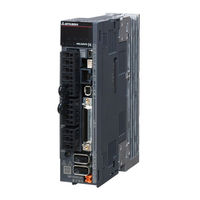
MELSERVO MR-J4-A-RJ Series
Mitsubishi Electric MELSERVO MR-J4-A-RJ Series Manuals
Manuals and User Guides for Mitsubishi Electric MELSERVO MR-J4-A-RJ Series. We have
2
Mitsubishi Electric MELSERVO MR-J4-A-RJ Series manuals available for free PDF download: Instruction Manual
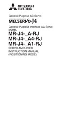
Mitsubishi Electric MELSERVO MR-J4-A-RJ Series Instruction Manual (416 pages)
Brand:
Mitsubishi Electric
| Category:
Amplifier
| Size: 2.78 MB
Table of Contents
Table of Contents
10
Functions and Configuration
16
For Proper Use of the Positioning Mode
16
Positioning Mode Specification List
17
Function List
19
Configuration Including Peripheral Equipment
22
Signals and Wiring
24
I/O Signal Connection Example
26
Point Table Method
26
Program Method
28
Indexer Method
30
Connectors and Pin Assignment
32
Signal (Device) Explanations
36
Analog Override
50
Interfaces
52
Internal Connection Diagram
52
Detailed Explanation of Interfaces
55
Source I/O Interfaces
59
Power-On Sequence
60
Display and Operation Sections
62
Display Sequence
63
Status Display
65
Diagnostic Mode
72
Alarm Mode
75
Point Table Setting
77
Parameter Mode
81
External I/O Signal Display
83
Output Signal (DO) Forced Output
84
Single-Step Feed
85
Teaching Function
87
How to Use the Point Table
88
Startup
89
Power on and off Procedures
89
Stop
89
Test Operation
90
Parameter Setting
91
Manual Operation Mode
91
JOG Operation
91
Point Table Setting
92
Actual Operation
92
Troubleshooting at Start-Up
92
Automatic Operation Mode
94
Automatic Operation Using Point Table
98
Manual Pulse Generator Operation
130
Home Position Return Mode
132
Outline of Home Position Return
132
Dog Type Home Position Return
135
Count Type Home Position Return
137
Data Set Type Home Position Return
139
Stopper Type Home Position Return
140
Home Position Ignorance (Servo-On Position as Home Position)
142
Dog Type Rear End Reference Home Position Return
143
Count Type Front End Reference Home Position Return
145
Dog Cradle Type Home Position Return
146
Dog Type Last Z-Phase Reference Home Position Return
148
Dog Type Front End Reference Home Position Return Type
150
Dogless Z-Phase Reference Home Position Return Type
152
Automatic Retract Function Used for the Home Position Return
153
Automatic Positioning to Home Position Function
154
Roll Feed Mode Using the Roll Feed Display Function
155
Point Table Setting Method
157
Setting Procedure
157
Detailed Setting Window
159
How to Use the Program
160
Startup
160
Power on and off Procedures
160
Stop
161
Test Operation
162
Parameter Setting
163
Actual Operation
164
Troubleshooting at Start-Up
164
Program Operation Method
165
Program Language
166
Basic Settings of Signals and Parameters
189
Timing Chart of the Program Operation
191
Manual Operation Mode
193
JOG Operation
193
Manual Pulse Generator Operation
194
Home Position Return Mode
196
Summary of Home Position Return
196
Dog Type Home Position Return
199
Count Type Home Position Return
201
Data Set Type Home Position Return
203
Stopper Type Home Position Return
204
Home Position Ignorance (Servo-On Position as Home Position)
205
Dog Type Rear End Reference Home Position Return
206
Count Type Front End Reference Home Position Return
208
Dog Cradle Type Home Position Return
210
Dog Type Last Z-Phase Reference Home Position Return
212
Dog Type Front End Reference Home Position Return Type
214
Dogless Z-Phase Reference Home Position Return Type
216
Automatic Retract Function Used for the Home Position Return
217
Serial Communication Operation
218
Positioning Operation Using the Program
218
Multi-Drop Method
219
Group Specification
220
Incremental Value Command Method
222
Roll Feed Mode Using the Roll Feed Display Function
223
Program Setting Method
224
Setting Procedure
224
Window for Program Edit
225
Indirect Addressing Window
226
How to Use Indexer
228
Startup
228
Power on and off Procedures
228
Stop
229
Test Operation
230
Parameter Setting
231
Actual Operation
232
Troubleshooting at Start-Up
232
Automatic Operation Mode
234
Automatic Operation Mode 1 (Rotation Direction Specifying Indexer)
235
Automatic Operation Mode 2 (Shortest Rotating Indexer)
239
Manual Operation Mode
242
Station JOG Operation
242
JOG Operation
245
Home Position Return Mode
247
Outline of Home Position Return
247
Torque Limit Changing Dog Type Home Position Return
249
Torque Limit Changing Data Set Type
251
Backlash Compensation and Digital Override
253
Safety Precautions
256
Parameters
258
Parameter List
258
Basic Setting Parameters ([Pr. PA
273
Gain/Filter Setting Parameters ([Pr. PB
286
Extension Setting Parameters ([Pr. PC
298
I/O Setting Parameters ([Pr. PD
309
Extension Setting 2 Parameters ([Pr. PE
319
Linear Servo Motor/DD Motor Setting Parameters ([Pr. PL
322
Option Setting Parameters ([Pr. Po
325
Positioning Control Parameters ([Pr. PT
325
How to Set the Electronic Gear
334
Electronic Gear Settings in the Point Table Method and Program Method
334
Electronic Gear Setting in the Indexer Method
335
Software Limit
336
Stop Method for LSP (Forward Rotation Stroke End) off or LSN (Reverse Rotation Stroke End) off
337
Stop Method at Software Limit Detection
338
Troubleshooting
340
Explanation for the Lists
340
Alarm List
341
Warning List
346
Options and Peripheral Equipment
348
MR-HDP01 Manual Pulse Generator
349
Communication Function
352
Command and Data No. List
352
Reading Command
353
Writing Commands
361
Detailed Explanations of Commands
365
External I/O Signal Status (DIO Diagnosis)
365
Input Device On/Off
370
Input Device On/Off (for Test Operation)
371
Test Operation Mode
372
Output Signal Pin On/Off (Output Signal (DO) Forced Output)
374
Point Table
375
Mark Detection Function (Current Position Latch)
383
Settings Equivalent to Previous Models
384
Relevant Matters to Monitor Information
385
Relevant Matters to Input/Output
386
Parameter Unit
390
External Appearance and Key Explanations
391
Specifications
392
Dimensions
392
Connection with Servo Amplifier
393
Single Axis
393
Multi-Drop Connection
394
Display
396
Outline of Screen Transition
396
Parameter Unit Setting
397
Monitor Mode (Status Display)
397
Alarm/Diagnosis Mode
400
Parameter Mode
402
Point Table Mode
403
Test Operation Mode
404
Error/Message List
409
Advertisement
Mitsubishi Electric MELSERVO MR-J4-A-RJ Series Instruction Manual (66 pages)
General purpose AC servo/linear encoder
Brand:
Mitsubishi Electric
| Category:
Servo Drives
| Size: 0.6 MB
Table of Contents
Table of Contents
4
1 Linear Encoder
6
Compatible Linear Encoder List
7
Linear Encoder Manufactured by Mitutoyo (Absolute Type)
10
At343A
10
At543A-Sc/At545A-Sc
15
St741A/St742A/St743A/St744A
20
Linear Encoder Manufactured by Heidenhain
26
LC 493M/LC 193M (Absolute Type)
26
LIDA 485 + EIB 392M/LIDA 487 + EIB 392M (Incremental Type)
30
Linear Encoder Manufactured by Magnescale
34
Sr77/Sr87/Sr75/Sr85
34
SL710 + PL101-RM/RHM (Incremental Type)
36
Linear Encoder Manufactured by Renishaw
41
RESOLUTE RL40M (Absolute Type)
41
RGH26_ (Incremental Type)
46
A/B/Z-Phase Differential Output Linear Encoder
51
2 Option Cable/Connector Sets
54
MR-EKCBL_M-H Encoder Cable
54
MR-ECNM Connector Set
55
MR-J3CN2 Connector Set
55
MR-J4THCBL03M Branch Cable
56
MR-J4FCCBL03M Branch Cable
57
3 Detailed Explanation of [Al. 2A Linear Encoder Error 1]
58
Appendix
60
App. 1 Production of Branch Cable for Linear Servo Motor
60
App. 2 Production of Branch Cable for Fully Closed Loop Control System
60
App. 3 Manufacturer List
60
Advertisement
Related Products
Mitsubishi Electric MELSERVO MR-J4-A Series
Mitsubishi Electric MR-J4-60A(-RJ)
Mitsubishi Electric MR-J4-350A(-RJ)
Mitsubishi Electric MR-J4-500A(-RJ)
Mitsubishi Electric MR-J4-60B(-RJ)
Mitsubishi Electric MR-J4W2-44B
Mitsubishi Electric MR-J4-40GF-RJ
Mitsubishi Electric MR-J4-500GF-RJ
Mitsubishi Electric MR-J4-11KB-RJ010
Mitsubishi Electric MR-J4 B Series
Mitsubishi Electric Categories
Air Conditioner
Controller
Projector
Inverter
Heat Pump
More Mitsubishi Electric Manuals
Login
Sign In
OR
Sign in with Facebook
Sign in with Google
Upload manual
Upload from disk
Upload from URL