Sign In
Upload
Manuals
Brands
Mitsubishi Electric Manuals
Servo Drives
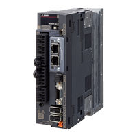
MR-J4-10B1(-RJ)
Mitsubishi Electric MR-J4-10B1(-RJ) Manuals
Manuals and User Guides for Mitsubishi Electric MR-J4-10B1(-RJ). We have
1
Mitsubishi Electric MR-J4-10B1(-RJ) manual available for free PDF download: Instruction Manual
Mitsubishi Electric MR-J4-10B1(-RJ) Instruction Manual (706 pages)
General-Purpose AC Servo MELSERVO-J4 SSCNET /H Interface MR-J4 series SERVO AMPLIFIER
Brand:
Mitsubishi Electric
| Category:
Servo Drives
| Size: 8.58 MB
Table of Contents
Table of Contents
10
1 Functions and Configuration
18
Summary
18
Function Block Diagram
20
Servo Amplifier Standard Specifications
30
Combinations of Servo Amplifiers and Servo Motors
36
Function List
38
Model Designation
40
Structure
41
Parts Identification
41
Removal and Reinstallation of the
54
Configuration Including Peripheral Equipment
56
2 Installation
70
Installation Direction and Clearances
71
Keeping out of Foreign Materials
73
Encoder Cable Stress
73
SSCNET III Cable Laying
73
Inspection Items
75
Parts Having Service Life
76
Restrictions When Using this Product at Altitude Exceeding 1000 M and up to 2000 M above Sea Level
77
3 Signals and Wiring
78
Input Power Supply Circuit
80
Class
81
Class
87
Class
91
I/O Signal Connection Example
92
For Sink I/O Interface
92
For Source I/O Interface
94
Explanation of Power Supply System
95
Signal Explanations
95
Power-On Sequence
96
Wiring CNP1, CNP2, and CNP3
97
Connectors and Pin Assignment
101
Signal (Device) Explanations
103
Input Device
103
Output Device
104
Output Signal
105
Power Supply
105
Forced Stop Deceleration Function
106
Base Circuit Shut-Off Delay Time Function
108
Vertical Axis Freefall Prevention Function
109
Residual Risks of the Forced Stop Function (EM2)
109
Alarm Occurrence Timing Chart
110
When You Use the Forced Stop Deceleration Function
110
When You Do Not Use the Forced Stop Deceleration Function
110
Interfaces
112
Internal Connection Diagram
112
Detailed Explanation of Interfaces
113
Source I/O Interfaces
115
SSCNET III Cable Connection
116
Servo Motor with an Electromagnetic Brake
118
Safety Precautions
118
Timing Chart
119
Grounding
123
4 Startup
124
Startup Procedure
125
Wiring Check
125
Switching Power on for the First Time
125
Surrounding Environment
129
Switch Setting and Display of the Servo Amplifier
131
Scrolling Display
134
Status Display of an Axis
134
Test Operation Mode
136
Test Operation Mode in MR Configurator2
136
Test Operation
137
Test Operation Mode in MR Configurator2
138
Motor-Less Operation in Controller
141
5 Parameters
144
Parameter List
144
Basic Setting Parameters ([Pr. PA
154
Gain/Filter Setting Parameters ([Pr. PB
165
Extension Setting Parameters ([Pr. PC_ _ ])
178
I/O Setting Parameters ([Pr. PD
185
Extension Setting 2 Parameters ([Pr. PE_ _ ])
191
Extension Setting 3 Parameters ([Pr. PF
194
Linear Servo Motor/DD Motor Setting Parameters ([Pr. PL_ _ ])
196
6 Normal Gain Adjustment
200
Different Adjustment Methods
200
Adjustment on a Single Servo Amplifier
200
Adjustment Using MR Configurator2
201
One-Touch Tuning
202
One-Touch Tuning Flowchart
204
Display Transition and Operation Procedure of One-Touch Tuning
206
Caution for One-Touch Tuning
216
Auto Tuning
217
Auto Tuning Mode
217
Auto Tuning Mode Basis
217
Adjustment Procedure by Auto Tuning
219
Response Level Setting in Auto Tuning Mode
220
Manual Mode
221
Gain Adjustment Mode
224
7 Special Adjustment Functions
228
Filter Setting
228
Machine Resonance Suppression Filter
229
Adaptive Filter II
232
Shaft Resonance Suppression Filter
234
Low-Pass Filter
235
Advanced Vibration Suppression Control II
236
Command Notch Filter
240
Gain Switching Function
242
Applications
242
Function Block Diagram
243
Parameter
244
Gain Switching Procedure
247
Tough Drive Function
251
Vibration Tough Drive Function
251
Instantaneous Power Failure Tough Drive Function
253
Compliance with SEMI-F47 Standard
257
Model Adaptive Control Disabled
260
Lost Motion Compensation Function
261
Super Trace Control
264
8 Troubleshooting
266
Explanation for the Lists
266
Alarm List
267
Warning List
277
Troubleshooting at Power on
280
9 Dimensions
282
Servo Amplifier
282
Connector
301
10 Characteristics
304
Overload Protection Characteristics
304
Power Supply Capacity and Generated Loss
308
Dynamic Brake Characteristics
311
Dynamic Brake Characteristics
312
Dynamic Brake Operation
312
Permissible Load to Motor Inertia When the Dynamic Brake Is Used
315
Cable Bending Life
316
Inrush Currents at Power-On of Main Circuit and Control Circuit
317
11 Options and Peripheral Equipment
320
Cable/Connector Sets
320
Combinations of Cable/Connector Sets
321
MR-D05UDL3M-B STO Cable
325
SSCNET III Cable
326
Battery Cable/Junction Battery Cable
328
Regenerative Options
329
Combination and Regenerative Power
329
Selection of Regenerative Option
331
Parameter Setting
334
Connection of Regenerative Option
334
Dimensions
339
FR-BU2-(H) Brake Unit
343
Selection
343
Brake Unit Parameter Setting
344
Connection Example
345
Dimensions
353
FR-RC-(H) Power Regeneration Converter
358
FR-CV-(H) Power Regeneration Common Converter
360
Selection
361
Model Designation
361
Junction Terminal Block PS7DW-20V14B-F (Recommended)
369
MR Configurator2
370
Specifications
370
System Configuration
371
Precautions for Using USB Communication Function
372
Battery
373
Selection of Battery
373
MR-BAT6V1SET Battery
373
MR-BAT6V1BJ Battery for Junction Battery Cable
377
MR-BT6VCASE Battery Case
381
MR-BAT6V1 Battery
387
Selection Example of Wires
388
Molded-Case Circuit Breakers, Fuses, Magnetic Contactors
392
Power Factor Improving DC Reactors
395
Power Factor Improving AC Reactors
397
Relay (Recommended)
400
Noise Reduction Techniques
401
Earth-Leakage Current Breaker
408
EMC Filter (Recommended)
411
External Dynamic Brake
418
Panel through Attachment (MR-J4ACN15K/MR-J3ACN)
424
Summary
430
Structure
431
Battery
432
Using MR-BAT6V1BJ Battery for Junction Battery Cable
433
Using MR-BT6VCASE Battery Case
434
13 Using Sto Function
436
Introduction
436
Residual Risks of the STO Function
437
Specifications
438
Maintenance
439
Signal (Device) Explanations
440
Connection Example
441
External I/O Signal Connection Example Using an MR-J3-D05 Safety Logic Unit
442
External I/O Signal Connection Example Using an External Safety Relay Unit
445
External I/O Signal Connection Example Using a Motion Controller
446
Detailed Description of Interfaces
447
Source I/O Interface
449
Functions and Configuration
450
Servo System with Auxiliary Equipment
451
Signals and Wiring
455
Operation and Functions
457
Magnetic Pole Detection
460
Home Position Return
469
Test Operation Mode in MR Configurator2
473
Operation from Controller
474
Function
476
12 Absolute Position Detection System
478
Characteristics
479
Power Supply Capacity and Generated Loss
480
Dynamic Brake Characteristics
481
Permissible Load to Motor Mass Ratio When the Dynamic Brake Is Used
482
16 Fully Closed Loop System
484
Functions and Configuration
484
Servo System with Auxiliary Equipment
485
Signals and Wiring
486
Operation and Functions
487
Startup Procedure
488
Magnetic Pole Detection
489
Operation from Controller
497
Function
498
Characteristics
500
Power Supply Capacity and Generated Loss
502
Dynamic Brake Characteristics
503
Functions and Configuration
506
Selecting Procedure of Control Mode
508
System Configuration
509
Load-Side Encoder
511
MR-J4FCCBL03M Branch Cable
513
Operation and Functions
514
Home Position Return
521
Operation from Controller
524
Fully Closed Loop Control Error Detection Functions
526
Auto Tuning Function
527
Absolute Position Detection System under Fully Closed Loop System
528
About MR Configurator2
529
17 Application of Functions
532
J3 Compatibility Mode
532
Operation Modes Supported by J3 Compatibility Mode
533
How to Switch J4 Mode/J3 Compatibility Mode
536
How to Use the J3 Compatibility Mode
537
Cautions for Switching J4 Mode/J3 Compatibility Mode
538
Cautions for the J3 Compatibility Mode
539
Change of Specifications of "J3 Compatibility Mode" Switching Process
540
Appendix
614
App. 1 Peripheral Equipment Manufacturer (for Reference)
614
App. 3 Symbol for the New EU Battery Directive
617
App. 4 Compliance with Global Standards
618
App. 5 MR-J3-D05 Safety Logic Unit
634
App. 6 EC Declaration of Conformity
652
App. 7 How to Replace Servo Amplifier Without Magnetic Pole Detection
655
App. 8 Two-Wire Type Encoder Cable for HG-MR/HG-KR
656
App. 9 SSCNET III Cable (SC-J3BUS_M-C) Manufactured by Mitsubishi Electric System Service
658
App. 11 Special Specification
670
App. 12 Driving On/Off of Main Circuit Power Supply with DC Power Supply
674
App. 13 Optional Data Monitor Function
676
App. 14 STO Function with SIL 3 Certification
679
App. 15 When Using the Servo Amplifier with the DC Power Supply Input
681
App. 16 Status of General-Purpose AC Servo Products for Compliance with the China Rohs Directive
686
Advertisement
Advertisement
Related Products
Mitsubishi Electric MR-J4-10B(-RJ)
Mitsubishi Electric MR-J4-10B-RJ010
Mitsubishi Electric MELSERVO MR-J4-10B
Mitsubishi Electric MR-J4-100A4(-RJ)
Mitsubishi Electric MR-J4-10GF
Mitsubishi Electric MR-J4-100GF-RJ
Mitsubishi Electric MR-J4-100B4-RJ010
Mitsubishi Electric MELSERVO MR-J4-100B
Mitsubishi Electric MR-J4-100B-RJ010
Mitsubishi Electric MR-J4-10GF-RJ
Mitsubishi Electric Categories
Air Conditioner
Controller
Projector
Inverter
Heat Pump
More Mitsubishi Electric Manuals
Login
Sign In
OR
Sign in with Facebook
Sign in with Google
Upload manual
Upload from disk
Upload from URL