Sign In
Upload
Manuals
Brands
Mitsubishi Electric Manuals
Air Conditioner
PFD-P250VM-E
Mitsubishi Electric PFD-P250VM-E Control Manuals
Manuals and User Guides for Mitsubishi Electric PFD-P250VM-E Control. We have
9
Mitsubishi Electric PFD-P250VM-E Control manuals available for free PDF download: Service Handbook, Operation Manual, Installation Manual, Data Book, Service Manual
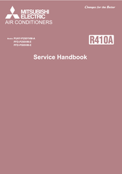
Mitsubishi Electric PFD-P250VM-E Service Handbook (326 pages)
Brand:
Mitsubishi Electric
| Category:
Air Conditioner
| Size: 40.67 MB
Table of Contents
Table of Contents
8
Chapter 1 Check before Servicing
10
Preparation for Piping Work
12
Read before Servicing
12
Tool Preparation
13
Handling and Characteristics of Piping Materials, Refrigerant, and Refrigerant Oil
14
Piping Materials
14
Pipe Processing
16
Storage of Piping Materials
16
Characteristics of the New and Conventional Refrigerants
17
Refrigerant Oil
18
Working with Refrigerant Piping
19
Pipe Brazing
19
Air Tightness Test
20
Vacuum Drying
21
Refrigerant Charging
22
Precautions for Wiring
23
Cautionary Notes on Installation Environment and Maintenance
25
Chapter 2 Restrictions
26
System Configurations
28
Types and Maximum Allowable Length of Cables
29
Switch Settings
30
Address Settings List
31
M-NET Address Settings
31
Outdoor Unit Power Jumper Connector Connection
31
Connection of Two Refrigerant Circuits
32
Outdoor Unit Centralized Controller Switch Setting
32
Settings of MA Remote Controller Main/Sub Switching Switch
32
Suction/Discharge Temperature Control Selection
32
Various Control Methods Using the Signal Input/Output Connector on Outdoor Unit
33
Demand Control Overview
35
System Connection Example
37
Example System with an MA Remote Controller
38
System with One Refrigerant
38
System with Two Refrigerant Circuits
40
System in Which Two MA Remote Controllers Are Connected to One Indoor Unit
42
System in Which Two Indoor Units Are Grouped with the MA Remote Controller
44
Restrictions on Refrigerant Pipe Length
46
Restrictions on Refrigerant Pipes
46
Restrictions on Refrigerant Pipe Size
47
Chapter 3 Major Components, Their Functions and Refrigerant Circuits
48
External Appearance and Refrigerant Circuit Components of Outdoor Unit
50
External Appearance of Outdoor Unit
50
Outdoor Unit Refrigerant Circuits
51
External Appearance and Internal Components of Indoor Unit
52
External Appearance of Indoor Unit
52
Internal Components of Indoor Unit
54
Refrigerant Circuit Diagrams
58
System with One Refrigerant Circuit
58
System with Two Refrigerant Circuits
60
Functions of the Major Components of Outdoor Unit
61
Functions of the Major Components of Indoor Unit
64
Procedure of Separating the Indoor Unit
65
Chapter 4 Electrical Components and Wiring Diagrams
70
Circuit Board Arrangement
72
Outdoor Unit Control Box
72
Indoor Unit Control Box
75
Circuit Board Components
76
Outdoor Unit Control Board
76
Outdoor Unit Power-Supply Board (PS Board)
77
Outdoor Unit Inverter Board (INV Board)
78
Outdoor Unit Fan Board
79
Outdoor Unit Noise Filter
80
Indoor Unit Control Board
81
Indoor Unit External Input/Output Circuit Board
82
Electrical Wiring Diagrams
83
Transmission Booster Electrical Wiring Diagrams
86
Chapter 5 Control
88
Dipswitch Functions and Factory Settings
90
Outdoor Unit Switch Functions and Factory Settings
90
Indoor Unit Switch Functions and Factory Settings
95
Function of the Switch <Remote Controller
97
Initial Control
98
Outdoor Unit Control
98
Overview
98
Rotation Control (Single Refrigerant Circuit)
98
Startup Control
98
Refrigerant Bypass Control
99
Frequency Control
100
Refrigerant Recovery Control
100
Control at Initial Startup
101
Control of Controller Cooling Function (Electronic Expansion Valve <LEV9>)
101
Outdoor Unit Fan Control
101
Refrigerant Flow Control (Linear Expansion Valves <Lev2A and Lev2B>)
101
Subcool Coil Control (Linear Expansion Valve <LEV1>)
101
Emergency Operation Mode
103
Demand Control
104
Operation Mode
104
Capacity Control between Outdoor Units (When Two Refrigerant Circuits Are Connected)
105
Control of IH Energization Without the Compressor in Operation
105
Dehumidification Priority Control
105
System Rotation Control Instructions
106
Indoor Unit Control
109
Operation Flow Chart
113
Chapter 6 Test Run
116
Read before Test Run
118
Evaluating and Adjusting Refrigerant Charge
119
Operation Characteristics and Refrigerant Charge
119
The Following Symptoms Are Normal
122
Initialization Procedure for System Rotation Settings
123
Chapter 7 Troubleshooting Using Error Codes
132
Error Code and Preliminary Error Code Lists
134
Error Code Definitions and Solutions: Codes [0 - 999]
138
Error Code [0403]
138
Error Code Definitions and Solutions: Codes [1000 - 1999]
139
Error Code [1102]
139
Error Code [1301]
140
Error Code [1302] (During Operation)
141
Error Code [1302] (at Startup)
142
Error Code [1500]
142
Error Code Definitions and Solutions: Codes [2000 - 2999]
143
Error Code [2503]
143
Error Code Definitions and Solutions: Codes [3000 - 3999]
144
Error Code [3511]
144
Error Code [3512]
145
Error Code Definitions and Solutions: Codes [4000 - 4999]
146
Error Code [4102]
146
Error Code [4106]
147
Error Code [4109]
147
Error Code [4121]
147
Error Codes [4220, 4225, 4226] Detail Code 108
149
Error Codes [4220, 4225, 4226] Detail Code 109
149
Error Code [4220] Detail Code 110
150
Error Codes [4235, 4236] Detail Code 125
154
Error Codes [4240, 4245, 4246]
155
Error Codes [4250, 4255, 4256] Detail Code 101
156
Error Codes [4250, 4255, 4256] Detail Code 104
156
Error Codes [4250, 4255, 4256] Detail Code 105
156
Error Codes [4250, 4255, 4256] Detail Codes 106 and 107
158
Error Code [4250] Detail Codes 121, 128, and 122
160
Error Codes [4255, 4256] Detail Code 137
160
Error Code [4260]
161
Error Code Definitions and Solutions: Codes [5000 - 5999]
162
Error Codes [5101, 5102, 5103, 5104]
162
Error Codes [5102,5103,5104,5105,5106,5107,5115]
163
Error Code [5110]
164
Error Code [5120]
165
Error Code [5201]
165
Error Codes [5305, 5306] Detail Code 135
168
Error Codes [5305, 5306] Detail Code 136
168
Error Code Definitions and Solutions: Codes [6000 - 6999]
170
Error Code [6201]
170
Error Code [6202]
170
Error Code [6600]
171
Error Code [6601]
171
Error Code [6602]
172
Error Code [6603]
172
Error Code [6606]
173
Error Code [6607] Error Source Address = Outdoor Unit (OC)
175
Error Code [6607] Error Source Address = Indoor Unit (IC)
176
Error Code [6607] Error Source Address = System Controller
178
Error Code [6607] All Error Source Addresses
179
Error Code [6607] no Error Source Address
180
Error Code [6608]
181
Error Code [6831]
181
Error Code [6832]
182
Error Code [6833]
182
Error Code [6834]
183
Error Code [6841]
184
Error Code [6842]
184
Error Code [6843]
185
Error Code Definitions and Solutions: Codes [7000 - 7999]
190
Error Code [7100]
190
Error Code [7101]
191
Error Code [7102]
192
Error Code [7105]
193
Error Code [7106]
193
Error Code [7110]
193
Error Code [7111]
193
Error Code [7113]
194
Error Code [7117]
194
Error Code [7130]
195
Chapter 8 Troubleshooting Based on Observed Symptoms
198
MA Remote Controller Problems
200
The LCD Does Not Light up
200
The LCD Momentarily Lights up and then Goes off
201
HO" and "PLEASE WAIT" Do Not Go off the Screen
202
Air Conditioning Units Do Not Operate When the on Button Is Pressed
203
Refrigerant Control Problems
204
Units in the Cooling Mode Do Not Operate at Expected Capacity
204
Outdoor Units Stop at Irregular Times
206
External Input Problems (Including Operation Mode)
207
Checking Transmission Waveform and for Electrical Noise Interference
208
M-Net
208
MA Remote Controller
210
Comparing the High-Pressure Sensor Measurement and Gauge Pressure
211
Pressure Sensor Circuit Configuration and Troubleshooting Pressure Sensor Problems
211
High-Pressure Sensor Configuration (63HS1)
212
Comparing the Low-Pressure Sensor Measurement and Gauge Pressure
213
Low-Pressure Sensor Configuration (63LS)
214
Troubleshooting Solenoid Valve Problems
215
Troubleshooting Outdoor Unit Fan Problems
217
General Overview on LEV Operation
218
Troubleshooting LEV Problems
218
Possible Problems and Solutions
221
Coil Removal Instructions
222
Inverter-Related Problems and Solutions
224
Troubleshooting Inverter Problems
224
Checking the Compressor for Ground Fault and Coil Resistance Problems
226
Checking the Inverter Board Error Detection Circuit
226
Checking the Inverter for Damage at No-Load
227
Checking the Inverter for Damage During Compressor Operation
228
Checking the Converter for Damage During Compressor Operation
230
Checking the Fan Board Error Detection Circuit at no Load
230
Checking the Fan Motor for Ground Fault and Coil Resistance Problems
230
Checking the Fan Board for Damage at no Load
231
Checking the Fan Board for Damage with Load
231
Checking the Installation Conditions
232
Solutions for the Main Breaker Trip
232
Solutions for the Main Earth Leakage Breaker Trip
233
Simple Check on Inverter Circuit Components
234
Troubleshooting Problems with IGBT Module
234
Checking the Fan Inverter Heatsink for Clogging
238
8-10 Control Circuit
239
Control Power Supply Function Block
239
Troubleshooting Problems with Outdoor Unit Transmission Power Supply Circuit
240
8-11 Measures for Refrigerant Leakage
242
8-12 Parts Replacement Instructions
244
Ensuring Maintenance Space (Preparation for the Maintenance of Refrigerant Circuit Parts)
244
Notes on Wiring Installation
246
Four-Way Valve and Check Valve Replacement Procedure
248
Compressor Replacement Procedure
256
Removal Instructions for the Control Box
258
Maintenance Procedure for the Drain Pan
260
Maintenance Procedures for the Heat Exchanger
262
Accumulator Replacement Procedure
267
Troubleshooting Problems Using the LED Status Indicators on the Outdoor Unit
269
Replacement Instructions for Motor and Bearing (Indoor Unit)
270
8-15 Maintenance/Inspection Schedule
276
Advertisement
Mitsubishi Electric PFD-P250VM-E Service Handbook (216 pages)
Brand:
Mitsubishi Electric
| Category:
Air Conditioner
| Size: 6.82 MB
Table of Contents
Safety Precautions
2
Before Installing the Unit
5
Before the Test Run
7
Table of Contents
8
Read before Servicing
10
Read before Servicing
12
I Read before Servicing
12
Necessary Tools and Materials
13
Piping Materials
14
Storage of Piping
16
Pipe Processing
16
Brazing
17
Air Tightness Test
18
Vacuum Drying (Evacuation)
19
Refrigerant Charging
20
Remedies to be Taken in Case of a Refrigerant Leak
20
Characteristics of the Conventional and the New Refrigerants
21
Notes on Refrigerating Machine Oil
22
II Restrictions
24
System Configuration
26
Types and Maximum Allowable Length of Cables
27
Switch Settings and Address Settings
29
An Example of a System to Which an MA Remote Controller Is Connected
31
Wiring Method/Address Setting Method
32
System with Two Refrigerant Circuits
33
System in Which Two MA Remote Controllers Connected to One Indoor Unit
35
System in Which Two Indoor Units Are Grouped with MA Remote Controller
37
Restrictions on Pipe Length
39
Outdoor Unit Components
40
Outdoor Unit Components and Refrigerant Circuit
42
Control Box of the Outdoor Unit
46
Outdoor Unit Circuit Board
48
Indoor Unit Components
52
External Dimensions
54
Indoor Unit Components and Internal Structure
56
Control Box of the Indoor Unit
60
Indoor Unit Circuit Board
61
Separating the Top and Bottom of the Indoor Unit
62
Electrical Wiring Diagram
66
Electrical Wiring Diagram of the Outdoor Unit
68
Electrical Wiring Diagram of the Indoor Unit
70
Refrigerant Circuit
72
Refrigerant Circuit Diagram
74
Principal Parts and Functions
77
Control
82
Functions and Factory Settings of the Dipswitches
84
Controlling the Outdoor Unit
89
Initial Control
89
Control at Start-Up
89
Bypass Control
89
Compressor Frequency Control
90
Defrost Operation Control
91
Refrigerant Recovery Control
92
Capacity Control of Outdoor Fan and Heat Exchanger
93
Subcool Coil Control (Linear Expansion Valve)
93
Control at Initial Start-Up
94
Emergency Operation Mode
95
Capacity Control between Outdoor Units
96
Dehumidification Priority Control
96
Operation Mode
96
Controlling the Indoor Unit
97
Thermostat Functions
97
Thermostat Reading
97
Actuator Control
98
Temperature Setting Range
98
Anti-Freeze Control (in Cooling Mode)
99
Switch between Pulse and Level of MA Remote Controller External Input
100
Operation During Electrical Power Failure
100
Operation Flow Chart
101
Operations in each Mode
103
Cooling Operation
103
Heating Operation (for Warming up the Indoor Unit)
104
Test Run Mode
106
Items to be Checked before a Test Run
108
Test Run Method
109
Operating Characteristic and Refrigerant Amount
110
Adjusting the Refrigerant Amount
111
Refrigerant Amount Adjust Mode
113
The Following Symptoms Are Normal
115
Standard Operation Data (Reference Data)
116
Troubleshooting
118
Error Code Lists
120
Responding to Error Display on the Remote Controller
123
Temperature Sensor Failure (Outdoor Unit)
135
Transmission Error
138
System with the Main Remote Controller Connected
141
Errors that Are Not Limited to a Particular System
142
System Error
144
Troubleshooting According to Malfunction of the Remote Controller
146
Flowchart When the MA Remote Controller Cannot be Operated
149
In Case of Main Remote Controller
150
In Case of External Input (Including Operation Mode)
152
Investigation of Transmission Wave Shape/Noise
153
M-NET Transmission
153
Wave Shape Check
153
MA Remote Controller Transmission
155
Troubleshooting Principal Parts
156
High-Prmessure Sensor (63HS)
156
Pressure Sensor Configuration
156
Low-Pressure Sensor (63LS)
157
Solenoid Valve
158
Outdoor Unit Fan
160
LEV Troubleshooting
161
Indoor Unit LEV
161
LEV Valve Closing and Opening Operation
161
Outdoor Unit LEV
162
Outdoor Unit LEV1 Coil Removal Procedure
164
Inverter Troubleshooting
165
Inverter Output Related Troubles
166
Trouble Treatment When the Main Power Breaker Is Tripped
169
Checking Procedure for Individual Components of Main Inverter Circuit
170
Intelligent Power Module (IPM)
171
Diode Stack
172
Control Circuit Troubleshooting
173
Control Power Source Function Block
173
Indoor Unit
173
Troubleshooting Transmission Power Circuit of Outdoor Unit
175
Refrigerant Leak
176
Leak Spot: in the Case of Extension Pipe for Indoor Unit
176
Leak Spot: in the Case of Outdoor Unit
176
Compressor Replacement Instructions (Only P500 Type)
177
Collecting the Cooling Liquid from the Accumulator (Only P500 Type)
178
Maintenance/Inspection Schedule
179
Approximate Long Evity of Various Parts
179
Details of Maintenance/Inspection
180
X LED Monitor Display on the Outdoor Unit Board
182
How to Read the LED on the Service Monitor
184
Mitsubishi Electric PFD-P250VM-E Operation Manual (88 pages)
Brand:
Mitsubishi Electric
| Category:
Air Conditioner
| Size: 11.25 MB
Table of Contents
English
6
Table of Contents
6
During Operation
6
Safety Precautions
6
Installation
6
Names and Functions of Various Parts
7
How to Operate
7
On/Off
7
Disposing of the Unit
7
Selecting Operation
8
Room Temperature Adjustment
8
Time Setting
8
Timer Setting
8
Failure" Display Lamps
9
The Smart Way to Use
9
Control of Indoor Unit Inlet or Outlet Temperature
9
Others
9
Fault Reset
9
Selecting Normal and Local Operation
9
Caring for the Unit
10
Troubleshooting
10
Installation, Transferring Works, And Checking
10
Checking Drainage
11
Checking V Belts
11
Cleaning The Indoor Unit Heat Exchanger
11
Greasing the Fan Bearings
11
When the Unit Is to be out of Use for a Long Time
11
Periodic Checks
12
Specifications
13
Warranty and Servicing
13
Deutsch
14
Einbau
14
Sicherheitsvorkehrungen
14
Während des Betriebs
14
Die Anlage Entsorgen
15
Namen und Funktionen der Teile
15
Bedienung
16
Betrieb, Halt
16
Betriebsart-Umschaltung
16
Regelung der Raumtemperatur
16
Zeiteinstellung
16
Fehler Zurücksetzen
17
Sonstiges
17
Wahl des Normal- und des Lokalbetriebs
17
Zeitschaltereinstellung
17
Failure"-Anzeigelampen
18
Geschickte Verwendung
18
Pflege der Anlage
18
Steuerung der Eingangs- oder Ausgangstemperatur des Innengerätes
18
Installation, Verlagerung und Prüfung
19
Störungssuche
19
Den Abfluss Überprüfen
20
Einfetten der Ventilatorlager
20
Reinigen des Wärmetauschers des Innengerätes
20
Wenn die Anlage für Lange Zeit Außer Dienst Gestellt werden soll
20
Überprüfung der Keilriemen
20
Regelmäßige Überprüfungen
21
Garantie und Wartung
22
Technische Daten
22
Français
23
Consignes de Sécurité
23
Installation
23
Pendant le Fonctionnement
23
Noms et Fonctions des Différents Éléments
24
Rangement de L'appareil
24
Comment Faire Fonctionner le Climatiseur
25
ON/OFF (Marche/Arrêt)
25
Réglage de la Température de la Pièce
25
Sélection du Mode de Fonctionnement
25
Réglage de L'heure
26
Réglage de la Minuterie
26
Réinitialisation des Pannes
26
Sélection du Fonctionnement Normal et Local
26
Autres
27
Comment Utiliser le Climatiseur Intelligemment
27
Contrôle des Températures D'entrée et de Sortie de L'appareil Intérieur
27
Entretien de L'appareil
27
Témoins D'affichage "Failure
27
Guide de Dépannage
28
Installation, Travaux en cas de Déplacement et Vérifications
28
Contrôle de L'écoulement
29
Contrôle des Courroies en V
29
Graissage des Paliers du Ventilateur
29
Lorsque le Climatiseur Ne Doit Pas Être Utilisé pendant une Longue Période
29
Nettoyage de L'échangeur de Chaleur de L'appareil Intérieur
29
Contrôles Périodiques
30
Garantie et Dépannage
31
Spécifications Techniques
31
Español
32
Durante el Funcionamiento
32
Instalación
32
Medidas de Seguridad
32
Eliminación de la Unidad
33
Nombres y Funciones de Los Diversos Componentes
33
Ajuste de la Temperatura de la Habitación
34
Cómo Manejar la Unidad
34
On/Off
34
Selección del Modo de Funcionamiento
34
Ajuste de la Hora
35
Otros
35
Programación del Temporizador
35
Reajuste de Avería
35
Selección de Funcionamiento Normal y Local
35
Consejos Prácticos para Usar el Acondicionador
36
Control de la Temperatura de Entrada y Salida de la Unidad Interior
36
Indicadores de "Failure
36
Mantenimiento de la Unidad
36
Instalación, Tareas de Transferencia y Verificación
37
Solución de Problemas
37
Comprobación de las Correas en V
38
Comprobación del Drenaje
38
Cuando la Unidad no Va a Utilizarse Durante un Periodo de Tiempo Prolongado
38
Engrase de Los Cojinetes del Ventilador
38
Limpieza del Intercambiador de Calor de la Unidad Interior
38
Comprobaciones Periódicas
39
Especificaciones
40
Garantía y Mantenimiento
40
Italiano
41
Durante Il Funzionamento Dell'unità
41
Installazione
41
Misure DI Sicurezza
41
Eliminazione Dell'unità
42
Nomi E Funzioni Delle Varie Parti
42
Accensione/Spegnimento
43
Come Far Funzionare I'unita
43
Modalità DI Funzionamento
43
Impostazione del Timer
44
Impostazione Dell'ora in Corso
44
Regolazione Della Temperatura Della Stanza
44
Reset Guasti
44
Selezione Funzionamento Normal E Local
44
Altri
45
Controllo Della Temperatura Dell'unità in Ingresso E in Uscita, Sezione Interna
45
Manutenzione Dell'unità
45
Spie "Failure
45
Uso Ottimale Dell'unità
45
Lavori D'installazione E DI Trasferimento - Ispezione
46
Ricerca Dei Guasti
46
Controllo Cinghie a V
47
Controllo Dello Scarico
47
Ingrassaggio Dei Cuscinetti Ventilatore
47
Lungo Inutilizzo Dell'unità
47
Pulizia Dello Scambiatore DI Calore Dell'unità
47
Controlli Periodici
48
Dati Tecnici
49
Garanzia E Manutenzione
49
Português
50
Durante a Operação
50
Instalação
50
Precauções de Segurança
50
Como Operar
51
Descarte da Unidade
51
Nomenclatura E Funções das Partes
51
Ajuste da Hora
52
Ajuste da Temperatura Ambiente
52
Ajuste Do Temporizador
52
On/Off
52
Selecção de Operação
52
Controlo da Entrada da Unidade Interna ou Temperatura de Saída
53
Lâmpadas de Indicação de "Failure" (Falha)
53
Outros
53
Reinicialização de Falha
53
Selecção da Operação Normal E Local
53
Manutenção da Unidade
54
O Modo Inteligente de Utilizar
54
Resolução de Problemas
54
Engraxamento Dos Rolamentos Do Ventilador
55
Instalação, Obras de Transferência E Verificação
55
Limpeza da Permutador de Calor da Unidade Interna
55
Verificação da Drenagem
55
Verificação das Cintas V
55
Quando Não Utilizar a Unidade por um Período Prolongado
56
Verificações Periódicas
56
Especificações
57
Garantia E Conserto
57
Türkçe
59
Emniyet Tedbirleri
59
Kurulum
59
Çal›Flt›Rma Esnas›Nda
59
Çal›Flt›Rma Flekli
60
Çeflitli Parçalar›N Isimleri Ve Görevleri
60
Ünitenin At›Lmas
60
Mod SeçIMI
61
Oda S›Cakl›¤› Ayar
61
On/Off
61
Zaman Ayar
61
Zaman Sayac› Ayar
61
Ar›Za S›F›Rlamas
62
Ar›Za" Gösterge Ifl›Klar
62
DI¤Erleri
62
Normal Ve Lokal Çal›Flt›Rma SeçIMI
62
Ünitenin Girifl Veya Ç›K›Fl S›Cakl›¤›N› Kontrol Etme
62
Ak›Ll› Kullan›M Flekli
63
Sorun Giderme
63
Ünitenin Bak›M
63
Boflaltma Kontrolü
64
Fan Yataklar›N› Ya¤Lama
64
Kay›Fllar›N› Kontrol Edin
64
Kurulum, Aktarma Iflleri Ve Kontrol
64
Ünitenin Is› DönüfltürüCüsünün Temizlenmesi
64
Periyodik Kontroller
65
Ünite Uzun Süre Boyunca Kullan›Lmayacak Ise
65
Garanti Ve Servis
66
Teknik Özellikler
66
Magyar
67
A Berendezés Selejtezése
68
A Különböző Alkatrészek Nevei És FunkcióI
68
A Működtetés Módja
69
Be/Ki
69
Helyiség HőMérsékletének Beállítása
69
Műveletválasztás
69
Normal És Local MűköDés Választása
69
Egyéb
70
Hiba Törlése
70
IDőbeállítás
70
IDőzítőbeállítás
70
A Beltéri Egység BejöVő Vagy Kimenő HőMérsékletének Vezérlése
71
Az Egység Gondozása
71
Hibát Jelző Lámpák
71
Praktikus Használat
71
Hibaelhárítás
72
Telepítés, Áthelyezés És Ellenőrzés
72
A Beltéri Egység Hőcserélőjének Tisztítása
73
A Kondenzvíz-Elvezetés Ellenőrzése
73
A Ventilátor Csapágyainak Kenése
73
Az Ékszíjak Ellenőrzése
73
Ha a Berendezés Hosszabb Ideig Leállításra Kerül
73
Rendszeres Ellenőrzések
74
Garancia És Szerviz
75
Műszaki Adatok
75
Advertisement
Mitsubishi Electric PFD-P250VM-E Service Handbook (241 pages)
Brand:
Mitsubishi Electric
| Category:
Air Conditioner
| Size: 4.84 MB
Table of Contents
Table of Contents
8
Read before Servicing
12
I Read before Servicing
12
Necessary Tools and Materials
13
Piping Materials
14
Storage of Piping
16
Pipe Processing
16
Brazing
17
Air Tightness Test
18
Vacuum Drying (Evacuation)
19
Refrigerant Charging
20
Remedies to be Taken in Case of a Refrigerant Leak
20
Characteristics of the Conventional and the New Refrigerants
21
Notes on Refrigerating Machine Oil
22
Restrictions
24
System Configuration
26
Types and Maximum Allowable Length of Cables
27
Switch Settings and Address Settings
29
An Example of a System to Which an MA Remote Controller Is Connected
33
Restrictions on Pipe Length
41
Outdoor Unit Components
42
Outdoor Unit Components and Refrigerant Circuit
44
Control Box of the Outdoor Unit
46
Outdoor Unit Circuit Board
47
Indoor Unit Components
52
External Dimensions
54
Indoor Unit Components and Internal Structure
56
Control Box of the Indoor Unit
60
Indoor Unit Circuit Board
61
Separating the Top and Bottom of the Unit
62
Electrical Wiring Diagram
66
Electrical Wiring Diagram of the Outdoor Unit
68
Electrical Wiring Diagram of the Indoor Unit
69
Refrigerant Circuit
72
Refrigerant Circuit Diagram
74
Principal Parts and Functions
76
Control
80
Functions and Factory Settings of the Dipswitches
82
Controlling the Outdoor Unit
87
Controlling the Indoor Unit
98
Operation Flow Chart
102
Test Run Mode
106
Items to be Checked before a Test Run
108
Test Run Method
109
Operating Characteristic and Refrigerant Amount
110
Adjusting the Refrigerant Amount
110
Refrigerant Amount Adjust Mode
112
The Following Symptoms Are Normal
114
Standard Operation Data (Reference Data)
115
Troubleshooting
116
Error Code Lists
118
Mitsubishi Electric PFD-P250VM-E Installation Manual (88 pages)
INDOOR UNIT
Brand:
Mitsubishi Electric
| Category:
Air Conditioner
| Size: 4.14 MB
Table of Contents
English
9
Indoor Unit
1
Installation Manual
1
1 Safety Precautions
9
Table of Contents
9
Before Installation and Electric Work
9
Precautions for Devices that Use R410A Refrigerant
9
Before Connecting to the Outdoor Unit
10
Before Getting Installed
10
Before Getting Installed (Moved) - Electrical Work
10
Before Starting the Test Run
10
2 Indoor Unit Accessories
10
3 Selecting an Installation Site
10
Securing Installation and Service Space
11
4 Installing the Unit
11
Hanging Unit
11
Fixing Unit
11
5 Refrigerant Pipe and Drain Pipe Specifications
11
6 Connecting Refrigerant Pipes and Drain Pipes
11
Refrigerant Piping Work
11
Drain Piping Work
12
7 Electrical Wiring
12
Power Supply Wiring
12
Connecting Remote Controller, Indoor and Outdoor Transmission Cables
13
Connecting Electrical Connections
13
Setting Addresses
13
External I/O Specifications
14
8 Remote Controller Operation Problems and Solutions
15
9 Test Operation (Read OPERATION MANUAL as Well)
15
10 Separating the Top and Bottom of the Unit
16
Deutsch
17
1 Sicherheitsvorkehrungen
17
Vor Installations- und Elektroarbeiten
17
Vorsichtsmaßnahmen für Vorrichtungen, die das Kältemittel R410A Verwenden
18
Vor der Aufstellung
18
Vor dem Einbau (der Ortsveränderung) - Elektroarbeiten
18
Vor Installationsbeginn
18
Vor dem Anschließen der Außenanlage
18
2 Versorgungseinrichtungen der Innenanlage
19
3 Einen Aufstellort Wählen
19
Gewährleistung von Freiraum für die Installation Sowie Bedienung und Wartung
19
4 Aufstellen der Anlage
19
Hängendes Gerät
19
Befestigung des Gerätes
19
5 Technische Daten der Kältemittel- und Kondensatablaufleitung
19
Technische Daten der Kältemittel- und Kondensatablaufleitung
20
6 Kältemittel- und Kondensatablaufleitungen Anschließen
20
Verrohrung der Kältemittelleitung
20
Verrohrung des Kondensatablaufs/Der Dränage
20
7 Elektroverdrahtung
21
Netzstromverdrahtung
21
Anschluß der Fernbedienungs-, Innen- und Außenübertragungskabel
21
Vornahme der Elektroanschlüsse
22
Adressen Einsetzen
22
Externe I/O Daten
22
8 Probleme und Lösungen Beim Betrieb der Fernbedienung
24
9 Test-Betrieb (Siehe Auch OPERATION MANUAL (Betriebsanleitung))
24
10 Ober- und Unterteil der Anlage Trennen
25
Español
35
1 Medidas de Seguridad
35
Antes de la Instalación y de las Conexiones Eléctricas
35
Precauciones para Aparatos que Utilizan Refrigerante R410A
36
Antes de la Instalación
36
Montaje Eléctrico Previo a la Instalación
36
Antes de Iniciar el Funcionamiento de Prueba
36
Antes de Conectar la Unidad Exterior
36
2 Componentes Suministrados con la Unidad Interior
37
3 Selección de un Lugar para la Instalación
37
Instalación de Seguridad y Espacio de Mantenimiento
37
4 Instalación de la Unidad
37
Suspensión de la Unidad
37
Fijación de la Unidad
37
5 Especificaciones de Los Tubos del Refrigerante y de Drenaje
37
Especificaciones de Los Tubos del Refrigerante y de Drenaje
38
6 Conexión de Los Tubos del Refrigerante y de Drenaje
38
Tareas con el Tubo del Refrigerante
38
Tareas con la Tubería de Drenaje
38
7 Cableado Eléctrico
39
Cable de Alimentación
39
Conexión de Los Cables de Transmisión del Mando a Distancia y de las Unidades Exterior E Interior
39
Realización de las Conexiones Eléctricas
40
Configuración de las Direcciones
40
Especificaciones de Entrada/Salida Externa
40
8 Problemas de Funcionamiento del Controlador Remoto y Soluciones
41
9 Prueba de Funcionamiento (Lea También el MANUAL de INSTRUCCIONES)
42
10 Separación de las Partes Superior E Inferior de la Unidad
42
Italiano
44
1 Misure DI Sicurezza
44
Collegamenti Elettrici
45
Precauzioni Per Le Unità Che Usano Il Refrigerante R410A
45
Prima DI Installare L'unità
45
Prima Dell'installazione (Trasporto) - Collegamenti Elettrici
45
Prima DI Iniziare la Prova DI Funzionamento
45
Prima del Collegamento All'unità Esterna
46
2 Accessori Della Sezione Interna
46
3 Selezione del Luogo D'installazione
46
Sicurezza Dell'installazione E Spazio DI Servizio
46
4 Installazione Dell'unità
46
Unità DI Sospensione
46
Fissaggio Dell'unità
46
5 Specifiche Delle Tubazioni del Refrigerante E DI Drenaggio
46
Specifiche Delle Tubazioni del Refrigerante E DI Drenaggio
47
6 Collegamento Delle Tubazioni del Refrigerante E DI Drenaggio
47
Collegamento Della Tubazione del Refrigerante
47
Collegamento Della Tubazione DI Drenaggio
47
7 Cablaggi Elettrici
48
Cavi DI Alimentazione
48
Collegamento del Comando a Distanza E Dei Cavi DI Trasmissione Delle Sezioni Interne Ed Esterne
48
Esecuzione Dei Collegamenti Elettrici
49
Impostazione Degli Indirizzi
49
Specifiche I/O Esterne
49
8 Problemi E Soluzioni Sul Funzionamento del Comando a Distanza
50
9 Funzionamento DI Prova (Leggere Anche Il MANUALE D'USO)
51
10 Separazione Delle Parti Superiore Ed Inferiore Dell'unità
51
Português
53
1 Precauções de Segurança
53
Antes da Instalação E Trabalhos Eléctricos
53
Precauções para Dispositivos que Utilizam O Refrigerador R410A
53
Antes de Iniciar a Instalação
54
Antes de Iniciar a Instalação (Mudança) - Trabalho Eléctrico
54
Antes de Iniciar a Operação de Teste
54
Antes de Ligar À Unidade Externa
54
2 Acessórios da Unidade Interna
54
3 Selecção Do Local de Instalação
55
Protegendo a Instalação E Espaço para Serviço
55
4 Instalação da Unidade
55
Unidade Pendente
55
Unidade de Fixação
55
5 Especificações Dos Tubos Do Refrigerante E da Drenagem
55
6 Ligação de Tubos de Refrigerante E de Drenagem
56
Trabalho da Tubulação de Refrigerante
56
Trabalho da Tubulação de Drenagem
56
7 Fiação Eléctrica
56
Fiação da Fonte de Alimentação
57
Ligação Do Telecomando E Dos Cabos de Transmissão Interno E Externo
57
Ligações Eléctricas
57
Ajustar Endereços
57
Especificações de Entrada/Saída Externa
58
8 Problemas E Soluções Na Operação Do Telecomando
59
9 Operação de Teste (Leia TambéM O Manual de Instruções)
59
10 Separação das Partes Superior E Inferior da Unidade
60
Türkçe
61
1 Emniyet Tedbirleri
61
Kurulum Ve Elektrik Tesisat›Na Bafllamadan Önce
61
R410A So¤Utucu Kullanan Cihazlarda Al›Nmas› Gereken Tedbirler
61
Montaja Bafllamadan Önce
62
Montaja Bafllamadan Önce (Tafl›Nma) - Elektrik Tesisat
62
Deneme Çal›Flt›Rmas›Na Bafllamadan Önce
62
D›Fl Ünite Ba¤Lant›S›N› Yapmadan Önce
62
2 Ünite Aksesuarlar
62
3 Kurulum Yerinin SeçIMI
63
Montaj Ve Servis Alan›N› Güvenli K›Lmak
63
4 Ünitenin Kurulumu
63
Üniteyi Monte Etme
63
Üniteyi Sa¤Lamlaflt›Rma
63
5 So¤Utucu Ve Boflaltma Borusu Özellikleri
63
6 So¤Utucu Ve Boflaltma Boru Ba¤Lant›Lar
64
So¤Utucu Boru Tesisat› Ifllemi
64
Boflaltma Borusu Tesisat› Ifllemi
64
7 Elektrik Tesisat
64
Güç Kayna¤› Tesisat
65
Uzaktan Kumanda, Iç Ve D›Fl Iletim Kablolar›N› Ba¤Lama
65
Elektrik Ba¤Lant›Lar›N› Yapmak
65
Adres Ayarlar
65
Harici I/O Özellikleri
66
8 Uzaktan Kumanda ‹Fllemlerinde Oluflabilecek Sorunlar Ve Çözümler
67
9 Deneme Çal›Flt›Rmas› (KULLANIM KILAVUZU' Nu da Okuyun)
67
10 Ünitenin Alt Ve Üst K›S›Mlar›N› Ay›Rma Ifllemi
68
Mitsubishi Electric PFD-P250VM-E Data Book (78 pages)
Brand:
Mitsubishi Electric
| Category:
Air Conditioner
| Size: 1.8 MB
Table of Contents
Table of Contents
8
I General Equipment Descriptions
10
Unit Configuration Table
10
Operable Temperature Range
12
Product Specifications
13
Specifications
13
External Dimensions
15
Center of Gravity
20
Electrical Wiring Diagrams
22
Optional Parts
26
Product Data
27
Capacity Curves
27
Sound Levels
31
Fan Characteristics Curves
33
System Design
36
Piping Design
36
Designing of Water Circuit System
40
Water Piping Work
51
Control Wiring
52
Types of Switch Settings and Setting Methods
53
Sample System Connection
55
External Input/Output Specifications
60
System Rotation Control
65
Notes on the Use of Optional Accessories
65
Caution for Refrigerant Leakage
66
Air Conditioning the Computer Room
67
Main Features of the Floor-Duct Air Conditioners
67
Features of Air-Conditioner for Computer Room
67
Step-By-Step Plan for the Implementation of the Air-Conditioning
68
Conditions for the Installation of Computer-Room Air Conditioners
69
Setting the Air Conditioners
70
Automatic Control of the Computer Room
72
Maintenance/Inspection
73
Maintenance/Inspection Schedule
73
Mitsubishi Electric PFD-P250VM-E Data Book (48 pages)
Brand:
Mitsubishi Electric
| Category:
Air Conditioner
| Size: 1.17 MB
Table of Contents
Table of Contents
3
Specifications
5
Main Features
5
List of Possible Combinations of Indoor and Outdoor Units
6
Unit Specifications
7
Capacity Curves
8
Cooling Capacity
8
Cooling Input
8
Part Load Performance
9
SHF Curves
10
Correction by Refrigerant Piping Length
12
Operation Limit
12
Sound Levels
13
Noise Level
13
NC Curves
14
Fan Characteristics Curves
15
External Dimensions
16
Electrical Wiring Diagrams
19
Refrigerant Circuit Diagram and Thermal Sensor
22
System Design
24
Refrigerant Piping System
24
Control Wiring
25
Types of Switch Settings and Setting Methods
26
Sample System Connection
28
External Input/Output Specifications
33
System Rotation Control
38
Notes on the Use of Optional Accessories
38
Air Conditioning the Computer Room
39
Main Features of the Floor-Duct Air Conditioners
39
Features of Air-Conditioner for Computer Room
39
Step-By-Step Plan for the Implementation of the Air-Conditioning
40
Conditions for the Installation of Computer-Room Air Conditioners
41
Setting the Air Conditioners
42
Automatic Control of the Computer Room
44
Maintenance/Inspection
45
Maintenance/Inspection Schedule
45
Mitsubishi Electric PFD-P250VM-E Service Manual (41 pages)
Brand:
Mitsubishi Electric
| Category:
Air Conditioner
| Size: 0.92 MB
Table of Contents
Table of Contents
1
1 Specifications
3
Main Features
3
List of Possible Combinations of Indoor and Outdoor Units
4
Unit Specifications
5
2 Capacity Curves
6
Cooling Capacity
6
Cooling Input
6
SHF Curves
7
Correction by Refrigerant Piping Length
8
Operation Limit
8
3 Sound Levels
9
Noise Level
9
NC Curves
10
Fan Characteristics Curves
10
4 External Dimensions
11
5 Electrical Wiring Diagrams
15
6 Refrigerant Circuit Diagram and Thermal Sensor
19
7 System Design
21
Refrigerant Piping System
21
Control Wiring
22
Types of Switch Settings and Setting Methods
23
Sample System Connection
25
External Input/Output Specifications
29
8 Air Conditioning the Computer Room
32
Main Features of the Floor-Duct Air Conditioners
32
Features of Air-Conditioner for Computer Room
32
Step-By-Step Plan for the Implementation of the Air-Conditioning
33
Conditions for the Installation of Computer-Room Air Conditioners
34
Setting the Air Conditioners
35
Automatic Control of the Computer Room
37
9 Maintenance/Inspection
38
Maintenance/Inspection Schedule
38
Mitsubishi Electric PFD-P250VM-E Operation Manual (13 pages)
Brand:
Mitsubishi Electric
| Category:
Air Conditioner
| Size: 0.81 MB
Table of Contents
Operation Manual
1
1 Safety Precautions
5
Table of Contents
5
During Operation
5
Installation
5
Disposing of the Unit
6
2 Names and Functions of Various Parts
6
3 How to Operate
6
On/Off
6
Selecting Operation
7
Room Temperature Adjustment
7
Time Setting
7
Timer Setting
7
4 “Failure” Display Lamps
8
Selecting Normal and Local Operation
8
Fault Reset
8
Others
8
Failure" Display Lamps
8
5 Control of Indoor Unit Inlet or Outlet Temperature
8
6 The Smart Way to Use
8
7 Caring for the Unit
9
8 Troubleshooting
9
9 Installation, Transferring Works, and Checking
9
10 Checking Drainage
10
11 Checking V Belts
10
12 Cleaning the Indoor Unit Heat Exchanger
10
13 Greasing the Fan Bearings
10
14 When the Unit Is to be out of Use for a Long Time
10
15 Periodic Checks
11
16 Specifications
12
17 Warranty and Servicing
12
Advertisement
Related Products
Mitsubishi Electric City Multi PFD-P250 500VM-E
Mitsubishi Electric CITY MULTI PFD-P250-A
Mitsubishi Electric PFD-P500VM-E
Mitsubishi Electric CITY MULTI PFD-500VM-A
Mitsubishi Electric PFD-500VM-E
Mitsubishi Electric PFFY-P63VLEM-A
Mitsubishi Electric CITY MULTI PFFY-P40VCM-E
Mitsubishi Electric CITY MULTI PFFY-P40VLRM-E
Mitsubishi Electric CITY MULTI PFFY-P20VEM-E
Mitsubishi Electric PFFY-VLRMM
Mitsubishi Electric Categories
Air Conditioner
Controller
Projector
Inverter
Heat Pump
More Mitsubishi Electric Manuals
Login
Sign In
OR
Sign in with Facebook
Sign in with Google
Upload manual
Upload from disk
Upload from URL