Sign In
Upload
Manuals
Brands
Mitsubishi Electric Manuals
Air Conditioner
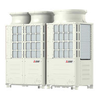
PUHY-EP300YJM-A
Mitsubishi Electric PUHY-EP300YJM-A Manuals
Manuals and User Guides for Mitsubishi Electric PUHY-EP300YJM-A. We have
1
Mitsubishi Electric PUHY-EP300YJM-A manual available for free PDF download: Service Handbook
Mitsubishi Electric PUHY-EP300YJM-A Service Handbook (355 pages)
Brand:
Mitsubishi Electric
| Category:
Air Conditioner
| Size: 8 MB
Table of Contents
Safety Precautions
2
Precautions for Handling Units for Use with the Product
4
Before Installing the Unit
5
Before the Test Run
7
Table of Contents
8
Read before Servicing
10
Read before Servicing
12
I Read before Servicing
12
Necessary Tools and Materials
13
Piping Materials
14
Copper Pipe Materials
14
Types of Copper Pipes
14
Radial Thickness
14
Flare Processing
15
Flare Nut
15
Storage of Piping
16
Pipe Processing
16
Sealing the Pipe Ends
16
Brazing
17
Air Tightness Test
18
Vacuum Drying (Evacuation)
19
Vacuum Pump with a Reverse-Flow Check Valve
19
Required Precision of Vacuum Gauge
19
Procedures for Stopping Vacuum Pump
19
Refrigerant Charging
20
Remedies to be Taken in Case of a Refrigerant Leak
20
Characteristics of the Conventional and the New Refrigerants
21
Refrigerant Composition
21
Pressure Characteristics
21
Notes on Refrigerating Machine Oil
22
Effects of Contaminants
22
Restrictions
24
System Configuration
26
Table of Compatible Indoor Units
26
High COP Combinations
27
Types and Maximum Allowable Length of Cables
28
Wiring Work
28
Control Wiring
28
M-NET Transmission Line
28
Switch Settings and Address Settings
29
Remote Controller Wiring
29
M-NET Address Settings
30
Power Supply Switch Connector Connection on the Outdoor Unit
31
Settings for the Centralized Control Switch for the Outdoor Unit
31
Selecting the Position of Temperature Detection for the Indoor Unit
31
Various Start-Stop Controls (Indoor Unit Settings)
31
Cooling-Only Setting for the Indoor Unit
32
Various Controls Using Input-Output Signal Connector on Outdoor Unit
32
Example of Wiring Connection
33
Demand Control
34
Contact Input and Control Content
34
8-Step Demand Control
35
12-Step Demand Control
35
Sample System Connection
36
An Example of a System to Which an MA Remote Controller Is Connected
37
Wiring Method
38
Indoor/Outdoor Transmission Line
38
MA Remote Controller Wiring
38
Address Setting Method
38
Sample Control Wiring
39
LOSSNAY Connection
40
Group Operation of Units in a System with Multiple Outdoor Units
41
An Example of a System to Which an ME Remote Controller Is Connected
47
An Example of a System to Which both MA Remote Controller and ME Remote Controller Are Connected
49
Restrictions on Pipe Length
51
Refrigerant Pipe Size
53
Outdoor Unit Components
56
Outdoor Unit Components and Refrigerant Circuit
58
Front View of an Outdoor Unit
58
Refrigerant Circuit Parts
60
Control Box of the Outdoor Unit Parts
62
Outdoor Unit Circuit Board
63
Fan Board
66
Remote Controller
68
Functions and Specifications of MA and ME Remote Controllers
70
Comparison of MA and ME Remote Controllers
70
Remote Controller Selection Criteria
70
Group Settings and Interlock Settings Via the ME Remote Controller
71
To Return to the Normal Display
72
Remote Controller Function Selection Via the ME Remote Controller
73
To Delete Group Settings
73
To Delete Interlock Settings
73
Skip-Auto-Mode Setting (Making Automatic Operation Mode Unselectable)
74
Operation Mode Display Selection Mode
74
Restricted Preset Temperature Range Mode
74
Temperature Range Setting for Heating/Automatic Mode
74
Interlock Settings Via the MA Remote Controller
75
Using the Built-In Temperature Sensor on the Remote Controller
76
Selecting the Position of Temperature Detection
76
Electrical Wiring Diagram
78
Electrical Wiring Diagram of the Outdoor Unit
80
Electrical Wiring Diagram of Transmission Booster
82
Refrigerant Circuit
84
Refrigerant Circuit Diagram
86
Principal Parts and Functions
88
Control
92
Functions and Factory Settings of the Dipswitches
94
Outdoor Unit Switches
94
Function of the Switch (Indoor Unit)
98
Function of the Switch - Remote Controller
99
Controlling the Outdoor Unit
101
Startup Sequence Rotation
101
Initial Control
101
Control at Start-Up
101
Bypass Control
102
Compressor Frequency Control
103
Pressure Limit
103
Discharge Temperature Limit
103
Periodic Frequency Control
103
Defrost Operation Control
104
Pipe Temperature
104
Stopping the Defrost Operation
105
Problems During Defrost Operation
105
Change in the Number of Operating Indoor Units During Defrosting
105
Refrigerant Recovery Control
106
Capacity Control of Outdoor Fan
106
Subcool Coil Control (Linear Expansion Valve LEV1)
107
Refrigerant Flow Control
107
Control at Initial Start-Up
107
Emergency Operation Mode
110
Starting the Emergency Operation
110
Ending the Emergency Operation
111
Communication Circuit Failure or When some of Outdoor Units Turned off
111
Operation Mode
112
Operation Flow Chart
114
Mode Determination Flowchart
114
Operations in each Mode
116
Test Run Mode
120
Items to be Checked before a Test Run
122
Test Run Method
123
Operating Characteristic and Refrigerant Amount
124
Adjusting the Refrigerant Amount
124
Amount of Refrigerant to be Added
125
Refrigerant Amount Adjust Mode
127
The Following Symptoms Are Normal
129
Standard Operation Data (Reference Data)
130
2-Unit Combination
136
3-Unit Combination
162
Single Unit (High-COP)
176
Troubleshooting
210
Error Code Lists
212
Responding to Error Display on the Remote Controller
215
Troubleshooting According to Remote Malfunction/External Input Error
267
Both for MA Remote Controller and ME Remote Controller
275
Investigation of Transmission Wave Shape/Noise
280
Troubleshooting Principal Parts
283
High-Pressure Sensor Troubleshooting
283
Low-Pressure Sensor Troubleshooting
284
Solenoid Valve Troubleshooting
285
Outdoor Unit Fan Troubleshooting
286
LEV Troubleshooting
288
Inverter Troubleshooting
294
Inverter Output Related Troubles
296
Trouble Treatment When the Main Power Breaker Is Tripped
298
Trouble Treatment When the Main Power Earth Leakage Breaker Is Tripped
298
Checking Procedure for Individual Components of Main Inverter Circuit
299
Troubleshooting for IGBT Module
299
Control Circuit Troubleshooting
301
Control Power Source Function Block
301
Indoor Unit
301
Troubleshooting Transmission Power Circuit of Outdoor Unit
302
Refrigerant Leak Troubleshooting
303
Leak Spot: in the Case of Extension Pipe for Indoor Unit
304
Leak Spot: in the Case of Outdoor Unit (Heating Season)
304
Compressor Replacement Instructions
305
Troubleshooting Using the Outdoor Unit LED Error Display
307
LED Monitor Display on the Outdoor Unit Board
308
How to Read the LED on the Service Monitor
310
LED Display at Initial Setting
310
Time Data Storage Function
311
LED Monitor Display - Current Data
312
LED Monitor Display - Data before Error
322
LED Monitor Display - Data on Indoor Unit System
329
LED Monitor Display - Setting Data
336
Data on Indoor Unit System
337
Other Types of Data
352
Advertisement
Advertisement
Related Products
Mitsubishi Electric PUHY-(E)P300
Mitsubishi Electric City Multi PUHY-EP300YNW-A
Mitsubishi Electric City Multi PUHY-EP350YNW-A
Mitsubishi Electric CITY MULTI PUHY-EP300YLM-BS
Mitsubishi Electric CITY MULTI PUHY-EP350YLM-BS
Mitsubishi Electric CITY MULTI PUHY-EP300YLM-A
Mitsubishi Electric CITY MULTI PUHY-EP350YLM-A
Mitsubishi Electric PUHY-EP-YHM-A
Mitsubishi Electric CITY MULTI PUHY-EP1050YSLM-BS
Mitsubishi Electric CITY MULTI PUHY-EP850YSLM-A
Mitsubishi Electric Categories
Air Conditioner
Controller
Projector
Inverter
Heat Pump
More Mitsubishi Electric Manuals
Login
Sign In
OR
Sign in with Facebook
Sign in with Google
Upload manual
Upload from disk
Upload from URL