Sign In
Upload
Manuals
Brands
Motorola Manuals
Two-Way Radio
Astro APX 3000
Motorola Astro APX 3000 Manuals
Manuals and User Guides for Motorola Astro APX 3000. We have
8
Motorola Astro APX 3000 manuals available for free PDF download: Detailed Service Manual, Basic Service Manual, User Manual, Manual, Quick Start Manual, Quick Reference Card
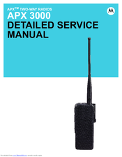
Motorola Astro APX 3000 Detailed Service Manual (474 pages)
Brand:
Motorola
| Category:
Two-Way Radio
| Size: 31.65 MB
Table of Contents
Foreword
3
Manual Revisions
3
Product Safety and Rf Exposure Compliance
3
Computer Software Copyrights
3
Document Copyrights
3
Disclaimer
3
Trademarks
3
Document History
5
Table of Contents
7
List of Tables
11
Related Publications
11
List of Figures
13
Commercial Warranty
19
Limited Warranty
19
Motorola Communication Products
19
Chapter 1 Introduction
23
General
23
Notations Used in this Manual
24
Chapter 2 Radio Power
25
General
25
Table 2-1. IMPRES Batteries
25
DC Power Routing
26
Figure 2-1. DC Power Distribution
26
Chapter 3 Theory of Operation
27
Main Board
28
Figure 3-1. APX 3000 Overall Block Diagram
28
Figure 3-2. Transceiver (UHF1/ UHF2) Block Diagram (Power and Control Omitted)
29
Figure 3-3. Transceiver (VHF) Block Diagram (Power and Control Omitted)
30
Figure 3-4. Transceiver (700/800 Mhz) Block Diagram (Power and Control Omitted)
31
Table 3-1. Battery Connector J3
31
Figure 3-5. Receiver Block Diagram (UHF1)
32
Figure 3-6. Receiver Block Diagram (UHF2)
33
Figure 3-7. Receiver Block Diagram (VHF)
33
Figure 3-8. Receiver Block Diagram (700/800 Mhz)
33
Figure 3-9. Transmitter Block Diagram (UHF1/ UHF2)
35
Figure 3-10. Transmitter Block Diagram (VHF)
36
Figure 3-11. Transmitter Block Diagram (700/800 Mhz)
36
Directional Coupler
37
Harmonic Filter
37
Antenna Switch
38
Figure 3-12. Synthesizer Block Diagram (UHF1/ UHF2)
40
Figure 3-13. Synthesizer Block Diagram (VHF)
41
Figure 3-14. Synthesizer Block Diagram (700/800 Mhz)
41
Controller
47
Figure 3-15. Controller Interconnection Diagram
47
Figure 3-16. Controller Electrical Overview
49
Figure 3-17. Controller DC Block Diagram
50
Table 3-2. DC Supplies and Sources for Controller
51
Table 3-3. Mako's LDO and Supplies
51
Figure 3-18. V_SW_1.4 Switched Power Supply
52
Table 3-4. Pulse Switching Combination
53
Figure 3-19. 5V Switched Power Supply
53
Figure 3-20. Power-Up Timing Regulators
54
Table 3-5. Controller Clock Distribution
55
Figure 3-21. Controller Clock Architecture
55
Figure 3-22. Overview of OMAP Interconnection with Controller Peripherals
56
Figure 3-23. OMAP Memory Interface
57
Figure 3-24. RX / TX SSI Configuration
58
Figure 3-25. Audio SSI Configuration
59
Figure 3-26. SPI and I2C Configuration
60
Figure 3-27. CPLD Block Diagram
61
Figure 3-28. Audio TX Path Block Diagram
62
Figure 3-29. RX Audio Path Block Diagram
63
Figure 3-30. Control Top Block Diagram
64
User Interface
64
Figure 3-31. GCAI Signal Configuration
65
Side Controls
65
Table 3-6. P1 Pin Assignment
66
Figure 3-32. GCAI Connector
66
Table 3-7. GCAI Connector Pin Assignment
67
Figure 3-33. APX 3000 Encryption Architecture
68
Table 3-8. Secure Board KIT Numbers
69
Global Positioning System (GPS)
70
Table 3-9. Power and I/O Pins for NL5500
71
Figure 3-34. GPS Block Diagram
71
Accelerometer
72
Table 3-10. SPI Interface
72
Figure 3-35. Accelerometer Block Diagram
72
Table 3-11. Register Address Map
73
Bluetooth
74
Figure 3-36. Relation of Bluetooth & LF Antenna Assembly to Main Board
74
Figure 3-37. Bluetooth Connection Flowchart
75
Figure 3-38. Bluetooth/Controller Interface with Clock Sources
76
Figure 3-39. Bluetooth Functional Block Diagram
76
Figure 3-40. Bluetooth Low-Frequency Circuit Block Diagram
77
Figure 3-41. Bluetooth Low-Frequency Pairing Data Path
77
Figure 3-42. Detailed Low-Frequency Transmit/Receive Paths
78
Figure 3-43. Chip Power-Up/Power-Down Sequence (Exernal Input/Output Shown)
78
Figure 3-44. Current Distribution Tree for Bluetooth Circuitry
79
Table 3-12. Bluetooth Host Processor UART I/O
80
Table 3-13. SPI I/O
81
Figure 3-45. Bluetooth LF UART Connection Block Diagram
81
Table 3-14. USB I/O
82
Figure 3-46. Bluetooth USB Interface to Main Board
82
Table 3-15. GPIO I/O
83
Chapter 4 Troubleshooting Procedures
85
Handling Precautions
85
Recommended Service Tools
86
Table 4-1. Recommended Service Tools
86
Standard Bias Table
87
Table 4-2. Standard Operating Bias - DC Voltages
87
Table 4-3. Standard Operating Bias - Clock Sources
87
Power-Up Self-Check Errors
88
Table 4-4. Power-Up Self-Check Error Codes
88
Power-Up Self-Check Diagnostics and Repair (Not for Field Use)
89
Table 4-5. Power-Up Self-Check Diagnostic Actions
89
Chapter 5 Troubleshooting Charts
91
List of Troubleshooting Charts
91
Table 5-1. Troubleshooting Charts
91
Main Troubleshooting Flowchart
93
Power-Up Failure
94
DC Supply Failure
105
Side Button Error
112
RX Audio Error
113
TX Audio Error
114
Keyload Failure
115
Secure Hardware Failure
116
RX RF Failure
117
5.11 FGU Failure
127
VCO Failure
129
5.13 GPS Failure
133
5.14 Bluetooth Failure - Pairing Issue
134
PA Failure
141
Chapter 6 Troubleshooting Waveforms
145
List of Waveforms
145
Table 6-1. List of Waveforms
145
Clocks
146
Figure 6-1. 32 Khz Clock Waveform
146
Figure 6-2. 4 Mhz Clock Waveform
147
Figure 6-3. 12 Mhz Clock Waveform
148
Figure 6-4. 16.8 Mhz Clock Waveform
149
Figure 6-5. 24 Mhz Clock Waveform
150
Audio SSI
151
Figure 6-6. Audio SSI - Red Tx Waveform
151
Figure 6-7. Audio SSI - Red Rx Waveform
152
Figure 6-8. Audio SSI - Sync. Waveform
153
Figure 6-9. Audio SSI - BCLK. Waveform
154
Rx Ssi
155
Figure 6-10. RX SSI - CLK. Waveform
155
Figure 6-11. RX SSI - da Waveform
156
Figure 6-12. RX SSI - Fsync. Waveform
157
Tx Ssi
158
Figure 6-13. TX SSI - TX CLK. Waveform
158
Figure 6-14. TX SSI - da Waveform
159
Figure 6-15. TX SSI - Fsync. Waveform
160
Spi
161
Figure 6-16. SPI - CLK Waveform
161
Figure 6-17. CS Waveform
162
I2C Bus
163
Figure 6-18. I2C Bus - SCA Waveform
163
Figure 6-19. I2C Bus - SCA 5V Waveform
164
Figure 6-20. I2C Bus - SDA Waveform
165
One Wire
166
Figure 6-21. 1-Wire Waveform
166
Gcai
167
Figure 6-22. GCAI - GPIO0 Waveform
167
Figure 6-23. GCAI - GPIO4 Waveform
168
6.10 Usb
169
Figure 6-24. USB - D- Waveform
169
Figure 6-25. USB - D+ Waveform
170
6.11 Sdram
171
Figure 6-26. SDRAM - CLK Waveform
171
Figure 6-27. SDRAM - CLKX Waveform
172
6.12 Flash Control
173
Figure 6-28. FLASH CONTROL - ADV Waveform
173
Figure 6-29. FLASH CONTROL - CS3 Waveform
174
Figure 6-30. FLASH CONTROL - OE Waveform
175
Figure 6-31. FLASH CONTROL - RDY Waveform
176
Figure 6-32. FLASH CONTROL - WE Waveform
177
6.13 Receive Baseband Signals
178
Figure 6-33. Received Baseband Waveforms
178
6.14 Gps
179
Figure 6-34. GPS TCXO Waveforms
179
Figure 6-35. GPS RTC Waveforms
180
Figure 6-36. GPS UART DATA Waveforms
181
6.15 Bluetooth Troubleshooting Waveforms
182
Table 6-2. Bluetooth Command to TX
182
Table 6-3. Bluetooth Command to RX
183
Table 6-4. Low Frequency Command to TX
183
Table 6-5. Low Frequency Command to RX
183
Table 6-6. Bluetooth Test Points
184
Figure 6-37. Summary of Bluetooth Power up Sequence
184
Figure 6-38. Startup Waveforms - Vmax of TP16
185
Figure 6-39. Startup - Timing Difference of TP9 to TP16
186
Figure 6-40. Startup - Timing Difference of TP5 to TP16 and Voltage Statistics
187
Figure 6-41. Startup - Timing Difference of TP4 to TP16 and Time Statistics
188
Figure 6-42. Startup - Timing Difference of TP4 to TP5 and Time Statistics
189
Figure 6-43. Startup - Vmax of TP5 and Time Statistics
190
Figure 6-44. Startup - Vmax of TP4 and Time Statistics
191
Figure 6-45. Startup - Vmax of TP5 and Voltage Statistics
192
Figure 6-46. Startup - Vmax of TP9 and Voltage Statistics
193
Figure 6-47. Startup - Vmax of TP10 and Time Statistics
194
Figure 6-48. Startup - Vmax of TP16 and Voltage Statistics
195
Figure 6-49. Startup - Vmax of TP13 and Voltage Statistics
196
Figure 6-50. Startup - Vmax of TP11 and Voltage Statistics
197
Figure 6-51. Startup - Timing Difference of TP13 to TP16 and Time Statistics
198
Figure 6-52. Startup - Timing Difference of TP10 to TP13 and Time Statistics
199
Figure 6-53. Startup - Timing Difference of TP11 to TP13 and Time Statistics
200
Figure 6-54. Bluetooth CW on Spectrum Analyzer
201
6.16 Bluetooth Steady-State
202
Figure 6-55. USB D+ Vmax and Packet Timing with Statistics
202
Figure 6-56. USB D- Vmax and Packet Timing with Statistics
203
Figure 6-57. V_SW_3.6 Voltage Statistics
204
Figure 6-58. 32 Khz Clock Vmax with Statistics
205
Figure 6-59. LF Coil When TX and RX
206
6.17 LF CW on Spectrum Analyzer
207
Figure 6-60. LF CW on Spectrum Analyzer
207
Chapter 7 Troubleshooting Tables
209
List of Board and IC Signals
209
Table 7-2. Mainboard to Main Flex Connector Interface Pin-Out
210
Table 7-3. Main Flex Connector to Main Board Connector Interface Pin-Out
211
Table 7-4. Side Button Flex Connector Pin-Out
212
Table 7-5. Top Control Flex Connector Pin-Out
212
Table 7-6. NFC Flex Connector Interface Pin-Out
213
Table 7-7. Overall GPIO Pin Functions
213
Table 7-8. Primary IC Reference Designator
221
Chapter 8 Schematics, Boards Overlays, and Parts Lists
223
List of Transceiver Schematics and Board Overlays
223
Table 8-1. List of Transceiver Schematics and Board Overlays
223
Figure 8-114.Connectors
223
Main Board Block: UHF1 (84012513001_A)
225
Figure 8-1. Main Board Block
225
Figure 8-2. Transceiver (RF) Board Overall Schematic Blocks
226
Figure 8-3. Antenna Switch Circuit
227
Figure 8-4. Transmitter HF Circuit
228
Figure 8-5. Power Amplifier Circuit
229
Figure 8-6. Automatic Level Control Circuit
230
Figure 8-7. Receiver Front End Circuit
231
Figure 8-8. Receiver Back End Mixer
232
Figure 8-9. Receiver Back End
233
Figure 8-10. Receiver VCO Circuit
234
Figure 8-11. Transmitter VCO Circuit
235
Figure 8-14. DC Circuit
238
Figure 8-15. Controller Overall Schematic Blocks
239
Figure 8-18. Top Control and JTAG Circuit
242
Figure 8-19. Lighting Control Circuit
243
Figure 8-20. GCAI and Side Control
244
Figure 8-21. Debugging and Display Connector
245
Figure 8-22. Connectors
246
Figure 8-23. CPLD Circuit
247
Figure 8-24. OMAP User Interface Circuit
248
Figure 8-25. Memory Interface
249
Figure 8-26. Audio Circuit
250
Figure 8-27. MAKO/DC Distribution Circuit
251
Figure 8-28. Serial Interface Circuit
252
Figure 8-29. Secure Circuit
253
Figure 8-30. Transceiver (RF) Board Layout - Top Side
254
Figure 8-31. Transceiver (RF) Board Layout - Bottom Side
255
Main Board Block: 700-800 Mhz (84012501002)
283
Figure 8-32. Main Board Block
283
Figure 8-33. Transceiver (RF) Board Overall Schematic
284
Figure 8-34. Receiver Back End
285
Figure 8-37. Automatic Level Control Circuit
288
Figure 8-38. VCO Circuit
289
Figure 8-39. Receiver Front End Circuit
290
Figure 8-40. Receiver Back End Mixer
291
Figure 8-41. Power Amplifier Circuit
292
Figure 8-42. DC Circuit
293
Figure 8-43. Antenna Switch Circuit
294
Figure 8-44. Transmitter HF Circuit
295
Figure 8-45. Controller Overall Schematic Blocks
296
Figure 8-48. Top Control and JTAG Circuit
299
Figure 8-49. Lighting Control Circuit
300
Figure 8-50. GCAI and Side Control
301
Figure 8-51. Debugging and Display Connector
302
Figure 8-52. Connectors
303
Figure 8-53. CPLD Circuit
304
Figure 8-54. OMAP User Interface Circuit
305
Figure 8-55. Memory Interface
306
Figure 8-56. Audio Circuit
307
Figure 8-57. MAKO/DC Distribution Circuit
308
Figure 8-58. Serial Interface Circuit
309
Figure 8-59. Secure Circuit
310
Figure 8-60. Transceiver (RF) Board Layout - Top Side
311
Figure 8-61. Transceiver (RF) Board Layout - Bottom Side
312
Main Board Block: VHF (84012512001_A)
339
Figure 8-62. Main Board Block
339
Figure 8-63. Transceiver (RF) Board Overall Schematic
340
Figure 8-64. ANTSWI Circuit
341
Figure 8-65. Transmitter HF Circuit
342
Figure 8-66. Power Amplifier Circuit
343
Figure 8-67. Automatic Level Control Circuit
344
Figure 8-68. Receiver Front End Circuit
345
Figure 8-69. Receiver Back End Mixer
346
Figure 8-70. Receiver Back End
347
Figure 8-71. Receiver VCO Circuit
348
Figure 8-72. Transmitter VCO Circuit
349
Figure 8-75. DC Circuit
352
Figure 8-76. Controller Overall Schematic Blocks
353
Figure 8-79. Top Control and JTAG Circuit
356
Figure 8-80. Lighting Control Circuit
357
Figure 8-81. GCAI and Side Control
358
Figure 8-82. Debugging and Display Connector
359
Figure 8-83. Connectors
360
Figure 8-84. CPLD Circuit
361
Figure 8-85. OMAP User Interface Circuit
362
Figure 8-86. Memory Interface
363
Figure 8-87. Audio Circuit
364
Figure 8-88. MAKO/DC Distribution Circuit
365
Figure 8-89. Serial Interface Circuit
366
Figure 8-90. Secure Circuit
367
Figure 8-91. Transceiver (RF) Board Layout - Top Side
368
Figure 8-92. Transceiver (RF) Board Layout - Bottom Side
369
Main Board Block: UHF2 (84012616001)
391
Figure 8-93. Main Board Block
391
Figure 8-94. Transceiver (RF) Board Overall Schematic
392
Figure 8-95. ANTSWI Circuit
393
Figure 8-96. Transmitter HF Circuit
394
Figure 8-97. Power Amplifier Circuit
395
Figure 8-98. Automatic Level Control Circuit
396
Figure 8-99. Receiver Front End Circuit
397
Figure 8-100.Receiver Back End Mixer
398
Figure 8-101.Receiver Back End
399
Figure 8-102.Receiver VCO Circuit
400
Figure 8-103.Transmitter VCO Circuit
401
Figure 8-106.DC Circuit
404
Figure 8-107.Controller Overall Schematic Blocks
405
Figure 8-110.Top Control and JTAG Circuit
408
Figure 8-111.Lighting Control Circuit
409
Figure 8-112.GCAI and Side Control
410
Figure 8-113.Debugging and Display Connector
411
Figure 8-115.CPLD Circuit
413
Figure 8-116.OMAP User Interface Circuit
414
Figure 8-117.Memory Interface
415
Figure 8-118.Audio Circuit
416
Figure 8-119.MAKO/DC Distribution Circuit
417
Figure 8-120.Serial Interface Circuit
418
Figure 8-121.Secure Circuit
419
Figure 8-122.Transceiver (RF) Board Layout - Top Side
420
Figure 8-123.Transceiver (RF) Board Layout - Bottom Side
421
Chapter 9 Debugging Fixture
449
Covert Board Debugging Fixture (Front)
449
Covert Board Debugging Fixture (Back)
450
Covert Board Debugging Fixture with Flexes, Housing and Display (Front)
450
Figure 9-3. Covert Board Debugging Fixtures with Flexes, Housing and Display (Front)
450
Covert Board Debugging Fixture with Flexes, Housing and Display (Back)
451
Debugging Fixture Set up
451
Figure 9-4. Covert Board Debugging Fixture with Flexes, Housing and Display (Back)
451
Figure 9-5. Remove the Housing Clamp
451
Figure 9-6. Remove the Display Clamp
452
Figure 9-7. Remove Transparent Cover (1)
452
Figure 9-8. Remove Transparent Cover (2)
453
Figure 9-9. Assemble NFC Flex
453
Board Assembly on Debugging Fixture
454
Figure 9-10. Board Assembly
454
Powering up Covert Board
455
Figure 9-11. Power up Covert Board
455
Advertisement
Motorola Astro APX 3000 Basic Service Manual (144 pages)
Brand:
Motorola
| Category:
Two-Way Radio
| Size: 15.27 MB
Table of Contents
Foreword
3
Manual Revisions
3
Product Safety and Rf Exposure Compliance
3
Computer Software Copyrights
3
Document Copyrights
3
Disclaimer
3
Trademarks
3
Document History
5
Table of Contents
7
Commercial Warranty
15
II. General Provisions
15
Limited Warranty
15
Motorola Communication Products
15
What this Warranty Covers and for How Long
15
III. State Law Rights
16
IV. How to Get Warranty Service
16
What this Warranty Does Not Cover
16
VI. Patent and Software Provisions
17
VII. Governing Law
17
Model Numbering, Charts, and Specifications
19
Chapter 1 Introduction
29
Manual Contents
29
Notations Used in this Manual
29
Radio Description
30
Flashport
30
Table 1-1. ASTRO APX 3000 Basic Features
30
Chapter 2 Basic Maintenance
31
General Maintenance
31
Safe Handling of CMOS and LDMOS Devices
31
Chapter 3 Basic Theory of Operation
33
Major Assemblies
33
Figure 3-1. APX 3000 Overall Block Diagram
33
Analog Mode of Operation
34
Figure 3-2. Receiver Block Diagram (UHF1)
34
Figure 3-3. Receiver Block Diagram (UHF2)
34
Figure 3-4. Receiver Block Diagram (VHF)
35
Figure 3-5. Receiver Block Diagram (700/800 Mhz)
35
Figure 3-6. GPS Diagram
35
Figure 3-7. Transmitter (UHF1/UHF2) Block Diagram
37
Figure 3-8. Transmitter (VHF) Block Diagram
37
Figure 3-9. Transmitter (700/800 Mhz) Block Diagram
38
Digital (ASTRO) Mode of Operation
39
Controller Section
39
Figure 3-10. Controller Block Diagram
39
Figure 3-11. Gps/Bluetooth/Accelerometer Block Diagram
41
Chapter 4 Recommended Test Equipment and Service Aids
43
Recommended Test Equipment
43
Table 4-1. Recommended Test Equipment
43
Service Aids
44
Field Programming
44
Table 4-2. Service Aids
44
Chapter 5 Performance Checks
45
Test Equipment Setup
45
Figure 5-1. Performance Checks Test Setup
45
Table 5-1. Initial Equipment Control Settings
46
Display Radio Test Mode
47
Table 5-2. Test-Mode Displays
47
Rf Test Mode
48
Table 5-3. Test Frequencies (Mhz)
49
Table 5-4. Test Environments
49
Receiver Performance Checks
50
Table 5-5. Receiver Performance Checks
50
Table 5-6. Receiver Tests for ASTRO Conventional Channels
51
Transmitter Performance Checks
52
Table 5-7. Transmitter Performance Checks - APX 3000
52
Table 5-8. Transmitter Tests for ASTRO Conventional Channels - APX 3000
53
Chapter 6 Radio Alignment Procedures
55
Test Setup
55
Figure 6-1. Radio Alignment Test Setup
55
Tuner Main Menu
56
Softpot
56
Figure 6-2. Tuner Software Main Menu
56
Figure 6-3. Typical Softpot Screen
57
Radio Information
58
Transmitter Alignments
58
Figure 6-4. Radio Information Screen
58
Reference Oscillator Alignment
58
Figure 6-5. Reference Oscillator Alignment Screen (UHF1)
59
Figure 6-6. Reference Oscillator Alignment Screen (UHF2)
60
Figure 6-7. Reference Oscillator Alignment Screen (VHF)
60
Figure 6-8. Reference Oscillator Alignment Screen (700/800 Mhz)
61
Table 6-1. Reference Oscillator Alignment
62
Figure 6-9. Transmit Power Characterization Points Alignment Screen (UHF1)
62
Figure 6-10. Transmit Power Characterization Points Alignment Screen (UHF2)
63
Figure 6-11. Transmit Power Characterization Points Alignment Screen (VHF)
63
Figure 6-12. Transmit Power Characterization Points Alignment Screen (700/800Mhz)
64
Figure 6-13. Transmit Power Characterization Alignment Screen (UHF1)
66
Figure 6-14. Transmit Power Characterization Alignment Screen (UHF2)
66
Figure 6-15. Transmit Power Characterization Alignment Screen (VHF)
67
Figure 6-16. Transmit Power Characterization Alignment Screen (700/800 Mhz)
67
Figure 6-17. PA Saturation Referencing Alignment Screen (UHF1)
68
Figure 6-18. PA Saturation Referencing Alignment Screen (UHF2)
69
Figure 6-19. PA Saturation Referencing Alignment Screen (VHF)
69
Figure 6-20. PA Saturation Referencing Alignment Screen (700/800 Mhz)
70
Figure 6-21. Transmit Deviation Balance Alignment Screen (UHF1)
72
Figure 6-22. Transmit Deviation Balance Alignment Screen (UHF2)
72
Figure 6-23. Transmit Deviation Balance Alignment Screen (VHF)
73
Figure 6-24. Transmit Deviation Balance Alignment Screen (700/800 Mhz)
73
Front End Filter Alignment
74
Figure 6-25. Front End Filter Alignment Screen (UHF1)
74
Performance Testing
75
Figure 6-26. Front End Filter Alignment Screen (UHF2)
75
Figure 6-27. Bit Error Rate Screen (UHF1)
77
Figure 6-28. Bit Error Rate Screen (UHF2)
77
Figure 6-29. Bit Error Rate Screen (VHF)
78
Figure 6-30. Bit Error Rate Screen (700/800 Mhz)
78
Figure 6-31. Transmitter Test Pattern Screen (UHF1)
79
Figure 6-32. Transmitter Test Pattern Screen (UHF2)
80
Figure 6-33. Transmitter Test Pattern Screen (VHF)
80
Figure 6-34. Transmitter Test Pattern Screen (700/800 Mhz)
81
Chapter 7 Encryption
83
Load an Encryption Key
83
Table 7-1. Kit Numbers for Secure-Enabled Boards
83
Multikey Feature
84
Select an Encryption Key
84
Erase an Encryption Key
84
Chapter 8 Disassembly/Reassembly Procedures
87
APX 3000 Exploded View (Main Subassemblies)
87
Table 8-1. APX 3000 Partial Exploded View Parts List
88
Figure 8-1. APX 3000 Partial Exploded View
88
Required Tools and Supplies
89
Fastener Torque Chart
89
Table 8-2. Required Tools and Supplies
89
Table 8-3. Required Tools and Supplies
89
Radio Disassembly
90
Figure 8-2. Removing the Thumb Screw
90
Figure 8-3. Removing the Antenna
91
Figure 8-4. Lifting up the Latch
92
Figure 8-5. Removing the Battery
92
Figure 8-6. Disengage the Chassis
93
Figure 8-7. Remove the Chassis Assembly
93
Figure 8-8. Remove the Chassis Screws
94
Figure 8-9. Remove the Secondary Shield Assembly
94
Figure 8-10. Remove the Main O-Ring at the Antenna Holder
95
Figure 8-11. Lift up the Main Board from the Chassis
95
Serviceable Components of the Main Sub-Assemblies
96
Figure 8-12. Remove Battery Seal
96
Figure 8-13. Serviceable Components - Main Board Assembly
96
Figure 8-14. Serviceable Components - Chassis Assembly
97
Table 8-4. Serviceable Components
98
Figure 8-15. Serviceable Components - Main Housing
100
Radio Reassembly
101
Figure 8-16. Assemble the Battery Seal
101
Figure 8-17. Assemble the Main O-Ring at Antenna Holder
101
Figure 8-18. Assemble the RF Board
102
Figure 8-19. Assemble the Secondary Shield Assembly
102
Figure 8-20. Torque in the Chassis Screws
103
Figure 8-21. Slide Chassis Assembly into Front Housing
103
Figure 8-22. Assemble Back Kit and Front Kit Together
104
Figure 8-23. Engaging Hook and Seating Cover
104
Figure 8-24. Securing the Cover
105
Figure 8-25. Attaching the Antenna
105
Figure 8-26. Assemble the Seal, Vacuum Port
106
Figure 8-27. Assemble the Label Gore Port
106
Figure 8-28. Assemble the Bottom Label
107
Figure 8-29. Attaching Battery - Slide into Position
107
Ensuring Radio Submergibility
108
Figure 8-30. Attaching Vacuum Test Fixture
110
Battery Contact Seal
112
Troubleshooting Leak Areas
112
Chapter 9 Basic Troubleshooting
113
Power-Up Error Codes
113
Table 9-1. Power-Up Error Code Displays
113
Operational Error Codes
114
Receiver Troubleshooting
114
Table 9-2. Operational Error Code Displays
114
Table 9-3. Receiver Troubleshooting Chart
114
Transmitter Troubleshooting
115
Table 9-4. Transmitter Troubleshooting Chart
115
Encryption Troubleshooting
116
Table 9-5. Encryption Troubleshooting Chart
116
Chapter 10 Exploded Views and Parts Lists
117
Table 10-1. APX 3000 Exploded Views and Controller Kit
117
10.1 APX 3000 Front Kit Exploded View
118
Figure 10-1. APX 3000 Front Kit Exploded View
118
10.2 APX 3000 Front Kit Exploded View Parts List
119
10.3 APX 3000 Back Kit Exploded View
120
Figure 10-2. APX 3000 Back Kit Exploded View
120
10.4 APX 3000 Back Kit Exploded View Parts List
121
Appendix A Accessories
123
Appendix B Replacement Parts Ordering
125
Basic Ordering Information
125
Transceiver Board Ordering Information
125
Motorola Online
125
Mail Orders
125
Telephone Orders
126
Fax Orders
126
Parts Identification
126
Product Customer Service
126
B.5 Telephone Orders
126
Motorola Astro APX 3000 User Manual (104 pages)
Brand:
Motorola
| Category:
Two-Way Radio
| Size: 9.73 MB
Table of Contents
Declaration of Conformity
5
Table of Contents
7
Important Safety Information
12
RF Energy Exposure and Product Safety Guide for Portable Two-Way Radios
12
Software Version
13
Notice to Users (FCC and Industry Canada)
13
Informations Importantes Sur la Sécurité
14
Exposition Aux Radiofréquences Et Sécurité du Produit Pour Radios Bidirectionnelles Portatives
14
Version du Logiciel
15
Avis Aux Utilisateurs (FCC Et Industrie Canada)
15
Computer Software Copyrights
16
Documentation Copyrights
16
Disclaimer
16
Getting Started
17
How to Use this Guide
17
Notations Used in this Manual
17
Additional Performance Enhancement
18
Crosstalk Prevention
18
Securenet
18
What Your Dealer/System Administrator Can Tell You
18
Preparing Your Radio for Use
19
Charging the Battery
20
Battery Charger
20
Attaching the Battery
21
Installing the Antenna
22
Attaching the Accessory Connector Cover
22
Installing Accessories with GCAI Connector
23
Turning on Your Radio
23
Adjusting the Volume
24
Pairing Radio with Pod and Earpiece
25
Pairing Radio with Mission Critical Remote Control Unit (RCU)
26
Using the Carry Holster
26
Inserting to the Carry Holster
26
Removing Your Radio from the Carry Holster
27
Tying Your Radio and Flexible Antenna to Your Body
28
Body
28
Positioning Your Radio and Devices on Your Body
28
Installing the Flexible Antenna
29
Strapping the Antenna Onto Your Body
31
Identifying Radio Controls
32
Radio Parts and Controls
33
Programmable Features
34
Assignable Radio Functions
34
Assignable Settings or Utility Functions
35
Accessing the Preprogrammed Functions
35
Multi-Functional Button (MFB)
35
Using Push-To-Talk (PTT) Button
36
Identifying Status Indicators
37
Status Icons
37
LED Indicator
39
LED Indicators in Surveillance Mode
40
Intelligent Lighting Indicators
41
Alert Tones
42
General Radio Operation
45
Selecting a Zone
45
Selecting a Radio Channel
46
Using Mode Select Feature
47
Saving a Zone and Channel to a Mode Select Button
47
Receiving and Responding to a Radio Call
48
Receiving and Responding to a Call
48
Receiving and Responding to a Private Call (Trunking Only)
49
Receiving and Responding to a Telephone Call (Trunking Only)
49
Making a Radio Call
50
Repeater or Direct Operation
50
Monitoring Features
51
Monitoring a Channel
51
Conventional Mode Operation
51
Advanced Features
52
Advanced Call Features
52
Receiving and Responding to a Selective Call (Conventional Only)
52
Using the Dynamic Regrouping Feature (Trunking Only)
53
Requesting a Reprogram (Trunking Only)
53
Classifying Regrouped Radios
54
Scan
54
Turning Scan on or off
54
Deleting a Nuisance Channel
55
Restoring a Nuisance Channel
55
Call Alert Paging
56
Receiving a Call Alert Page
56
Emergency Operation
56
Sending an Emergency Alarm
57
Sending an Emergency Call (Trunking Only)
58
Sending an Emergency Alarm with Emergency Call
58
Sending a Silent Emergency Alarm
59
Changing Channels During Emergncy
59
Using the Emergency Keep-Alive Feature
59
Man down
60
Pre-Alert Timer
61
Post-Alert Timer
61
Alerting Tones When man down Feature Is Triggered
61
Triggering Emergency
62
Alerting User When man down Enhanced Is Triggered
62
Exiting man down Feature
63
Re-Initiating man down
63
Testing the man down Feature
63
Secure Operations
64
Selecting Secure Transmissions
64
Selecting Clear Transmissions
64
Managing Encryption
65
Loading an Encryption Key
65
Using the Multikey Feature
65
Erasing All the Selected Encryption Keys
66
Requesting an Over-The-Air Rekey (ASTRO Only)
66
MDC Over-The-Air Rekeying (OTAR) Page
67
Infinite UKEK Retention
67
Hear Clear
67
Using Radio Kill
68
Using Direct Kill
68
Trunking System Controls
68
Using the Failsoft System
68
Going out of Range
69
Using the Site Trunking Feature
69
Mission Critical Wireless - Bluetooth
70
Turning the Bluetooth on
70
Turning the Bluetooth off
70
Re-Pair Timer
71
Bluetooth Drop Timer
72
Pairing with LF MPP Pairing Feature
72
Indicating the Bluetooth Connection Is Lost
74
Pairing with Standard Pairing Feature
74
Searching and Pairing with the Bluetooth Device
75
Turning Bluetooth Visibility on
75
Receiving Pairing Request from Other Devices
76
Turning the Bluetooth Audio on (Routing the Audio from Your Radio to the Headset)
76
Turning the Bluetooth Audio off (Routing the Audio from the Headset to Your Radio)
76
Adjusting the Volume of Your Radio from Bluetooth Audio Device
76
Clearing All Bluetooth Devices Information
77
Programming over Project 25 (POP 25) (ASTRO 25 and ASTRO Conventional)
77
Voice Announcement
78
Using Site Selectable Alerts (ASTRO 25)
79
Utilities
79
Flipping the Display on DRSM
79
Controlling the Display Backlight
79
Locking and Unlocking the Controls
80
Turning Voice Mute on or off
80
Using the Time-Out Timer
81
Using the Conventional Squelch Operation Features
81
Analog Options
81
Digital Options
81
Using the Digital PTT ID Feature
82
Using the Smart PTT Feature (Conventional Only)
82
Voice Announcement
83
Helpful Tips
84
Troubleshooting
84
Caring for Your Radio
85
Cleaning Your Radio
86
Handling Your Radio
86
Servicing Your Radio
87
Taking Care of the Battery
87
Checking the Battery Charge Status
87
LED and Sounds
87
Fuel Gauge Icon
87
Battery Recycling and Disposal
88
Accessories
89
Highlights for the Accessories
89
Advertisement
Motorola Astro APX 3000 User Manual (98 pages)
Brand:
Motorola
| Category:
Two-Way Radio
| Size: 9.39 MB
Table of Contents
Declaration of Conformity
5
Table of Contents
7
Important Safety Information
11
RF Energy Exposure and Product Safety Guide for Portable Two-Way Radios
11
Software Version
12
Notice to Users (FCC and Industry Canada)
12
Informations Importantes Sur la Sécurité
13
Exposition aux Radiofréquences et Sécurité du Produit pour Radios Bidirectionnelles Portatives
13
Version du Logiciel
14
Avis aux Utilisateurs (FCC et Industrie Canada)
14
Computer Software Copyrights
15
Documentation Copyrights
15
Disclaimer
16
Getting Started
17
How to Use this Guide
17
Notations Used in this Manual
17
Additional Performance Enhancement
18
Dynamic System Resilience (DSR)
18
Crosstalk Prevention
18
Encrypted Integrated Data (EID)
18
Securenet
18
What Your Dealer/System Administrator Can Tell You
19
Preparing Your Radio for Use
19
Charging the Battery
21
Battery Charger
21
Attaching the Battery
21
Installing the Antenna
22
Attaching the Accessory Connector Cover
23
Installing Accessories with GCAI Connector
23
Turning on Your Radio
24
Adjusting the Volume
25
Pairing Radio with Pod and Earpiece
25
Pairing Radio with Mission Critical Remote Control Unit (RCU)
26
Using the Carry Holster
27
Inserting to the Carry Holster
27
Removing Your Radio from the Carry Holster
27
Tying Your Radio and Flexible Antenna to Your Body
28
Body
28
Positioning Your Radio and Devices on Your Body
29
Installing the Flexible Antenna
29
Strapping the Antenna Onto Your Body
31
Identifying Radio Controls
32
Radio Parts and Controls
33
Programmable Features
34
Assignable Radio Functions
34
Assignable Settings or Utility Functions
35
Accessing the Preprogrammed Functions
35
Multi-Functional Button (MFB)
35
Using Push-To-Talk (PTT) Button
36
Identifying Status Indicators
36
Status Icons
36
LED Indicator
38
LED Indicators in Surveillance Mode
39
Intelligent Lighting Indicators
40
Alert Tones
41
General Radio Operation
44
Selecting a Zone
44
Selecting a Radio Channel
45
Using Mode Select Feature
46
Saving a Zone and Channel to a Mode Select Button
46
Receiving and Responding to a Radio Call
47
Receiving and Responding to a Call
47
Receiving and Responding to a Private Call (Trunking Only)
48
Receiving and Responding to a Telephone Call (Trunking Only)
48
Making a Radio Call
49
Repeater or Direct Operation
49
Monitoring Features
50
Monitoring a Channel
50
Conventional Mode Operation
50
Advanced Features
51
Advanced Call Features
51
Receiving and Responding to a Selective Call (Conventional Only)
51
Using the Dynamic Regrouping Feature (Trunking Only)
52
Requesting a Reprogram (Trunking Only)
52
Classifying Regrouped Radios
53
Scan
53
Turning Scan on or off
53
Deleting a Nuisance Channel
54
Restoring a Nuisance Channel
54
Call Alert Paging
55
Receiving a Call Alert Page
55
Emergency Operation
55
Sending an Emergency Alarm
56
Sending an Emergency Call (Trunking Only)
56
Sending an Emergency Alarm with Emergency Call
57
Sending a Silent Emergency Alarm
58
Using the Emergency Keep-Alive Feature
58
Man down
59
Pre-Alert Timer
60
Post-Alert Timer
60
Alerting Tones When man down Feature Is Triggered
60
Triggering Emergency
61
Exiting man down Feature
61
Re-Initiating man down
61
Testing the man down Feature
62
Secure Operations
63
Selecting Secure Transmissions
63
Selecting Clear Transmissions
63
Managing Encryption
64
Loading an Encryption Key
64
Using the Multikey Feature
64
Erasing All the Selected Encryption Keys
65
Requesting an Over-The-Air Rekey (ASTRO Only)
65
Hear Clear
66
Infinite UKEK Retention
66
MDC Over-The-Air Rekeying (OTAR) Page
66
Using Radio Kill
67
Using Direct Kill
67
Trunking System Controls
67
Using the Failsoft System
67
Going out of Range
68
Using the Site Trunking Feature
68
Mission Critical Wireless - Bluetooth
69
Turning the Bluetooth on
69
Turning the Bluetooth off
69
Re-Pair Timer
69
Bluetooth Drop Timer
70
Pairing the Bluetooth Device with Your Radio
71
Indicating the Bluetooth Connection Is Lost
72
Turning the Bluetooth Audio on (Routing the Audio from Your Radio to the Headset)
72
Adjusting the Volume of Your Radio from Bluetooth Audio Device
73
Clearing All Bluetooth Devices Information
73
Turning the Bluetooth Audio off (Routing the Audio from the Headset to Your Radio)
73
Programming over Project 25 (POP 25) (ASTRO 25 and ASTRO Conventional)
74
Utilities
74
Controlling the Display Backlight
74
Flipping the Display on DRSM
74
Locking and Unlocking the Controls
75
Turning Voice Mute on or off
75
Using the Time-Out Timer
75
Analog Options
76
Digital Options
76
Using the Conventional Squelch Operation Features
76
Using the Digital PTT ID Feature
77
Using the Smart PTT Feature (Conventional Only)
77
Voice Announcement
78
Helpful Tips
79
Troubleshooting
79
Caring for Your Radio
80
Cleaning Your Radio
81
Handling Your Radio
81
Servicing Your Radio
82
Taking Care of the Battery
82
Checking the Battery Charge Status
82
Fuel Gauge Icon
82
LED and Sounds
82
Battery Recycling and Disposal
83
Accessories
84
Highlights for the Accessories
84
Appendix: Maritime Radio Use in the VHF Frequency Range
85
Special Channel Assignments
85
Emergency Channel
85
Non-Commercial Call Channel
85
Operating Frequency Requirements
86
Declaration of Compliance for the User of Distress and Safety Frequencies
88
Motorola Astro APX 3000 Manual (59 pages)
RF ENERGY EXPOSURE AND PRODUCT SAFETY GUIDE FOR PORTABLE TWO-WAY RADIOS
Brand:
Motorola
| Category:
Two-Way Radio
| Size: 4 MB
Table of Contents
RF Energy Exposure Awareness and Control Information and Operational Instructions for Occupational Use
2
Federal Communication Commission (FCC) Regulations
3
RF Exposure Compliance and Control Guidelines and Operating Instructions for Two-Way Radio Operations
4
Electromagnetic Interference/Compatibility
6
Medical Devices
6
Acoustic Safety
8
Operational Warnings
8
Potentially Explosive Atmospheres
9
Intrinsically Safe Radio Information
10
Operational Cautions
10
Operational Cautions for Intrinsic Safe Equipment
11
Warnings for Radios Approved as Intrinsically Safe
11
Folleto de Normas de Seguridad y Exposición a la Energía de RF al Usar Radios Bidireccionales Portátiles
15
Información sobre Exposición a la Energía de RF y Su Control, E Instrucciones Operacionales para Uso como Herramienta Ocupacional
16
Pautas de Conformidad y Control de la Exposición de RF E Instrucciones de Operación
18
Accesorios Aprobados
19
Información Adicional
20
Interferencia y Compatibilidad Electromagnética
20
Aparatos Médicos
21
Otros Dispositivos Médicos
21
Seguridad Acústica
22
Advertencias Operacionales
23
Ambientes Potencialmente Explosivos
23
Información sobre Radios Intrínsecamente Seguros
25
Precauciones Operacionales para Unidades Intrínsecamente Seguras
25
Advertencias en Torno a Los Radios Aprobados como Intrínsecamente Seguros
26
Folheto de Normas de Segurança E de Exposição À Energia de RF para Rádios Portáteis Bidirecionais
29
Informações sobre a Exposição À Energia de RF E Seu Controle, E Instruções Operacionais para O Uso como Ferramenta Ocupacional
30
Regulamentos da Comissão Federal de Comunicações Dos EUA (FCC)
31
Orientações Gerais de Conformidade E Controle da Exposição de RF E Instruções de Operação
33
Interferência E Compatibilidade Eletromagnética
34
Dispositivos Médicos
35
Segurança Acústica
36
Advertências Operacionais
37
Informações sobre Rádios Intrinsecamente Seguros
39
Precauções Operacionais para Unidades Intrinsecamente Seguras
39
Advertências para Rádios Aprovados como Intrinsecamente Seguros
40
Brochure Normes de Sécurité Et Exposition À L'énergie de RF Pour L'utilisation des Radios Bidirectionnelles Portatives
43
Régulations du Conseil FéDéral Américain des Communications (FCC)
45
Directives en Matière de Conformité Et de Contrôle D'exposition Aux RF Et Consignes de Fonctionnement
47
Accessoires Approuvés
48
Informations Complémentaires
48
Interférence Et Compatibilité Électromagnétique
48
Dispositifs Médicaux
49
Stimulateurs Cardiaques
49
Aides Auditives
49
Autres Dispositifs Médicaux
50
Sécurité Acoustique
50
Avertissements de Fonctionnement
51
Atmosphères Potentiellement Explosives
51
Informations Sur Les Radios À Sécurité Intrinsèque
53
Précautions de Fonctionnement Pour Les Unités À Sécurité Intrinsèque
54
Avertissements Concernant Les Radios Approuvées de Sécurité Intrinsèque
55
Motorola Astro APX 3000 Quick Start Manual (2 pages)
Digital Portable Radios Flexible Antenna
Brand:
Motorola
| Category:
Antenna
| Size: 1.36 MB
Motorola Astro APX 3000 Quick Reference Card (2 pages)
Brand:
Motorola
| Category:
Portable Radio
| Size: 2.4 MB
Motorola Astro APX 3000 Quick Start Manual (2 pages)
Digital Portable Radios Flexible Antenna
Brand:
Motorola
| Category:
Portable Radio
| Size: 1.17 MB
Advertisement
Related Products
Motorola APX 3000
Motorola ASTRO APX 3000 P25
Motorola APX 3
Motorola APX 6000XE MODEL 1
Motorola APX650005
Motorola APX 1000 3
Motorola APX 6000XE 3
Motorola APX 6000XE 1
Motorola APX 6000
Motorola APX 2000 3
Motorola Categories
Cell Phone
Two-Way Radio
Baby Monitor
Cordless Telephone
Radio
More Motorola Manuals
Login
Sign In
OR
Sign in with Facebook
Sign in with Google
Upload manual
Upload from disk
Upload from URL