Sign In
Upload
Manuals
Brands
Motorola Manuals
Motherboard
CPV5000
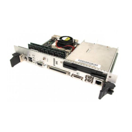
Motorola CPV5000 Single Board Computer Manuals
Manuals and User Guides for Motorola CPV5000 Single Board Computer. We have
1
Motorola CPV5000 Single Board Computer manual available for free PDF download: Installation And Reference Manual
Motorola CPV5000 Installation And Reference Manual (144 pages)
CompactPCI Single Board Computer
Brand:
Motorola
| Category:
Motherboard
| Size: 0.84 MB
Table of Contents
Table of Contents
7
Chapter 1 CPV5000 Single Board Computer Overview
17
About this Book: Changes between IH2 and IH3
17
Introduction
17
Additional Features
18
Input/Output Interfaces
19
Table 1-1. Input/Output Interfaces
19
Figure 1-1. Block Diagram
20
Special Functions
21
Additional Information Resources
21
Chapter 2 Getting Started
23
Before Installing the CPV5000
24
Installation Instructions
25
Figure 2-1. Installing the CPV5000
26
Powering up the CPV5000
27
Coin Battery
27
Front Panel
28
Figure 2-2. Front Panel Connectors and Leds
28
Antistatic Precautions
23
Chapter 3 Connectors and Components on the CPV5000
29
Components
29
Table 3-1. Major Chip Functions
29
Figure 3-1. Location of Main Components on the CPV5000
30
Connecting to and Configuring Headers
31
CPU Speed Settings
32
Table 3-2. CPU Speed Settings
32
CPU Voltage Settings
33
Ethernet Configuration
33
Table 3-3. Ethernet Configuration Jumpers
33
USB Configuration
34
Front Panel Connectors
34
Table 3-4. USB Configuration Jumpers
34
Table 3-5. Front Panel Connectors
34
Rear I/O Connectors
35
On-Board Connectors
35
Table 3-6. Rear I/O Connectors
35
Table 3-7. On-Board Connectors
35
Connectors J4 and J5
36
Table 3-8. J4 Connector Pin Assignments
36
J4 Signal Descriptions
37
Eideb (ATA-2), TTL Levels
37
Ethernet, RS422 Levels
37
General
37
Misc. Signals, TTL Levels
37
SCSI, X3T10 Spi/Single Ended Levels
38
VGA Video, VGA Levels
39
Table 3-9. J5 Connector Pin Assignments
40
J5 Signal Descriptions
41
General
41
Miscellaneous Signals
41
Keyboard/Auxiliary Device, TTL Levels
41
Universal Serial Bus (USB) (0 & 1), USB Levels
41
Parallel LPT Port, TTL Levels (some Signals Are Redefined When Used in EPP/ECP Modes)
42
Serial COM Ports (a & B), RS232 Levels
42
Floppy Disk Drive, TTL Levels
42
Eidea (ATA-2), TTL Levels
43
Parallel Port Connector
44
Table 3-10. Parallel Connector Pin Assignments
44
EIDE Hard Drive Connectors
45
Table 3-11. EIDE Connector Pin Assignments
45
Floppy Connector
47
Table 3-12. Floppy Connector Pin Assignments
47
PS/2 Keyboard/Mouse Connector
49
Table 3-13. Keyboard/Mouse Connector Pin Assignments
49
Serial Ports COM1 and COM2 Connectors
50
Table 3-14. COM1 and COM2 Pin Assignments
50
Fan Power Connector
51
USB Ports 1 and 2
51
Table 3-15. Fan Power Pin Assignments
51
Table 3-16. USB Ports Pin Assignments
51
Ethernet Connector
52
Table 3-17. Ethernet Connector Pin Assignments
52
SCSI Connector
53
Table 3-18. 68-Pin SCSI-3 Connector Pin Assignments
53
Video Connector
55
Table 3-19. Video Connector Pin Assignments
55
Reset Switch
56
Table 3-20. Reset Switch Pin Assignments
56
Chapter 4 Functional Description
57
PCI Device Mapping and Routing
58
Table 4-1. PCI Components
58
PCI Routing Table
59
Applications
59
Watchdog Timer
59
Table 4-2. PCI Interrupt Routing
59
I/O Address Map
60
Table 4-3. I/O Addresses
61
Memory Address Mapping
62
Table 4-4. Memory Address
62
Video Controller
63
Table 4-5. Standard Video Modes
63
Table 4-6. Extended Video Modes
64
Ultra SCSI Controller
67
Figure 4-1. SCSI Termination
68
EIDE Interface
70
Floppy Interface
70
Table 4-7. On-Board Drive Options
70
Parallel Port
71
Serial Ports
71
Usb
71
Keyboard/Mouse Interface
72
Ethernet
72
DMA Channels
72
Table 4-8. DMA Channels
72
Interrupts
73
Table 4-9. Interrupts
73
FPGA Access, Watchdog and ENUM Registers
74
Port Offset 0Bh: Board Status and Watchdog Strobe
74
Table 4-10. I/O Offset 0Bh (Write)
74
Table 4-11. I/O Offset 0Bh (Read)
74
I/O Port Offset 0Dh: FPGA Register Index Port
75
Table 4-12. FPGA Register Index Port
75
Table 4-13. FPGA Register Index
75
I/O Port Offset 0Fh: FPGA Register Data Port
76
Table 4-14. FPGA Register Data Port
76
Watchdog Index Mode
76
Watchdog Register: FPGA Index - 03H
76
Bit 7 - Clear Watchdog Bit
77
Bits 4-3 Watchdog Mode
77
Table 4-15. Watchdog Register
77
Table 4-16. Watchdog Mode
77
Bits 2-0 Watchdog Timer Delay
78
ENUM Status and Control
78
ENUM Status and Control Register: FPGA Index - 11H
78
Table 4-17. Watchdog Timer Delay
78
Table 4-18. Register Data Port When I/O Port 75H: FPGA
78
ENUM Storage Register: FPGA Index - 12H
79
Table 4-19. ENUM Storage
79
Chapter 5 Installing Options
81
System Memory Configurations
81
Table 5-1. Memory Configurations
82
Installing DRAM Simms
83
Installation Instructions
83
Upgrading the CPU
84
Installation Instructions
84
Table 5-2. CPU Speed Settings
85
Removing and Replacing the Battery
86
Installing the On-Board Disk Drives
87
Installation Instructions
87
Chapter 6 Power on Self-Tests
91
POST Phases
91
BIOS Error Reporting
92
Table 6-1. BIOS Error Reporting
92
Beep Codes
93
Table 6-2. Beep Codes
93
AMIBIOS Displayed Error Messages
94
Table 6-3. AMIBIOS Error Messages
94
POST Memory Test
97
ISA NMI Handler Messages
97
Table 6-4. ISA NMI Handler Messages
97
BIOS Revision
98
AMIBIOS Configuration Screen
98
POST Checkpoint Codes
99
Uncompressed Initialization Codes
99
Table 6-5. Uncompressed Initialized Codes
99
Runtime Checkpoint Codes
100
Table 6-6. Runtime Checkpoint Codes
100
Bus Checkpoint Codes
105
Table 6-7. Bus Checkpoint Codes
106
Additional Bus Checkpoints
107
Table 6-8. Additional Bus Checkpoints
107
Peripheral Component Interconnect (PCI) Local Bus
57
Chapter 7 Winbios Setup
109
Starting Winbios Setup
109
Winbios Setup Features
109
Icon-Based User Interface
109
Automatic Option Selection
109
Help Screens
110
Automatic Winbios Setup Option Selection
110
Point and Click Interface
110
Mouse Support
110
Memory Test Tick Sound
111
Using a Mouse with Winbios Setup
111
Using the Keyboard with Winbios Setup
112
Table 7-1. Keystroke Combinations
112
Winbios Setup Main Menu
113
Table 7-2. Winbios Setup Main Menu
113
Winbios Setup Types
114
Standard Setup
114
Date/Time
114
Floppy Drive a and B
114
Table 7-3. Winbios Setup
114
Configuring an MFM Drive
115
Pri Master Pri Slave Sec Master Sec Slave
115
Table 7-4. Drive Parameter Descriptions
116
User-Defined Drive
116
Configuring IDE Drives
117
Table 7-5. LBA Mode
117
Configuring a CD-ROM Drive
118
Hard Disk Drive Type
118
Table 7-6. Hard Drive Type Information
118
Advanced Setup
120
Quick Boot
120
Table 7-7. Advanced Setup Settings
120
Bootup Numlock
121
Bootup Sequence
121
Floppy Drive Seek
121
Floppy Drive Swap
121
Mouse Support
121
Primary Display
121
External Cache
122
Internal Cache
122
Password Check
122
Table 7-8. Internal Cache
122
System BIOS Shadow Cacheable
123
Chipset Setup
124
DRAM Speed
124
IRQ12/M Mouse Function
124
Memory Hole
124
Refresh Rate
124
Turbo Lead Readoff
124
Fast RAS to cas Delay Clock Cycle Setting
125
Leadoff Timing
125
Read Burst Timing
125
Speculative Readoff
125
Turnaround Insertion
125
Write Burst Timing
125
DRAM Data Integrity Mode
126
ECC Test Enable
126
Extended Cachebility
126
NA Disable (NAD) for External Cache
126
Bad Parity on Uncorrectable Err
127
Green PC Monitor Power State
127
Instant on Support
127
Power Management
127
Power Management Setup
127
SERR# Duration Mode
127
SERR# Output Type
127
Full on to Standby Timeout
128
Hard Disk Power down Mode
128
Hard Disk Timeout
128
Standby to Suspend Timeout
128
Video Power down Mode
128
Display Activity
129
Enabling Event Monitoring
129
Slow Clock Ratio
129
Pci/Pnp Setup
130
Plug and Play Aware os
130
PCI Latency Timer (in PCI Clocks)
130
PCI VGA Palette Snoop
130
PCI IDE Bus Master
130
Offboard PCI IDE Board
130
DMA Channels
131
ISA/PCI IRQ Allocation
131
Reserved Memory Size
132
Reserved Memory Address
132
Peripheral Setup
132
Onboard FDC
132
Onboard Serial Port 1/COM 1
132
Onboard Serial Port 2/COM 2
133
Onboard Parallel Port
133
Parallel Port Mode
133
Parallel Port DMA
133
Onboard IDE
134
Utility Menu
134
Detect IDE
134
Language
134
Security
135
Supervisor and User Icons
135
Two Levels of Passwords
135
Setting a Password
136
Changing a Password
136
Remember the Password
136
Anti-Virus
137
Default
138
Original
138
Optimal
138
Fail-Safe
138
Advertisement
Advertisement
Related Products
Motorola CPV5300 CompactPCI
Motorola CPV5300TM80
Motorola CPCI-6115
Motorola CPCI-6020
Motorola CompactPCI CPV5350
Motorola CPEI 150 series
Motorola CPEi 25800
Motorola CPEo 400 Series
Motorola CPEi 825 Series
Motorola CP110 VHF
Motorola Categories
Cell Phone
Two-Way Radio
Baby Monitor
Cordless Telephone
Radio
More Motorola Manuals
Login
Sign In
OR
Sign in with Facebook
Sign in with Google
Upload manual
Upload from disk
Upload from URL