Sign In
Upload
Manuals
Brands
Motorola Manuals
Radio
Spectra
Motorola Spectra Manuals
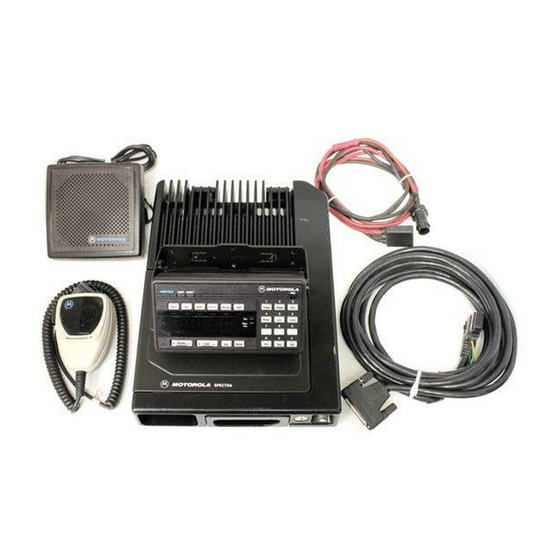
Manuals and User Guides for Motorola Spectra. We have
3
Motorola Spectra manuals available for free PDF download: Service Manual, Installation Manual
Motorola Spectra Service Manual (96 pages)
900 MHz Two-W ay FM Radios
Brand:
Motorola
| Category:
Radio
| Size: 0.49 MB
Table of Contents
Table of Contents
2
Performance Specifications for Spectra Conventional 4 Watt and 30 Watt Radios
5
Performance Specifications for Spectra Privacy Plus
6
Trunked/Conventional 900 Mhz Radio
6
Performance Specifications for Spectra Smartnet
7
Tm Trunked/Conventional 900 Mhz Radio
7
Performance Specifications for Spectra 9000 Radios (900 Mhz, 30 Watts)
8
Performance Specifications for Spectra 9000 Control Unit and Speaker
9
MODEL CHART for SPECTRA 900 Mhz TWO-WAY MOBILE FM RADIOS
10
MODEL CHART for SPECTRA 900 Mhz CONTROL HEAD BUTTON KITS (All Package Models)
11
MODEL CHART for SPECTRA 9000 CONTROL UNIT BUTTON KITS (All Package Models)
13
SPECTRA 900 Mhz FM TWO-WAY RADIO OPTIONS CHART
18
Spectra 9000 900 Mhz Fm Two-Way Radio Options Chart
19
Spectra Radio Service Aids
20
I. Scope and Purpose
22
Radio Model Identification
22
Radio Instruction Sheet
23
Trunked Mode Information
23
Conventional Mode Information
23
Trunked System Information
23
I. General
23
Theory Overview
26
Operation
26
Control Head (Spectra)
26
I. GENERAL (See Functional Block Diagram)
26
Figure 1 Typical Spectra Control Heads
27
Transceiver
28
Table 1 Control Head Jumper Table
28
Table 2 Serial Data Bus Logic States
28
Table 3 VCO Frequency
29
Table 4 VCO Power Output (Typical, Dbm)
29
Power Amplifiers
30
Figure 2 Functional Block Diagram for Pushbutton Control Head
31
CONTROL UNIT (Spectra 9000)
32
Figure 3 Typical Systems 9000 Control Unit
32
Table 5 Mode Jumper Placement
33
Table 6 EEPROM Jumper Table
34
Figure 4 Disassembly of the Control Unit
35
Table 7 VIP Output Connections
36
Table 8 VIP Input Connections
36
Front Panel Programming and Adjustments
37
ENTER PROGRAMMING MODE (See Figure 6.)
37
Top-Level Menu
37
Figure 5 Systems 9000 Control and Programming Control Controls
38
Figure 6 Top-Level Menu
38
CHANGE PARAMETERS ASSOCIATED WITHA ZONE (See Figure 8.)
39
Change Zone Names
39
Figure 7 Lower-Level Menu Structure
39
Figure 8 Zone Parameters Menu
39
Edit Zone Scan Lists
40
CHANGE PARAMETERS ASSOCIATED WITHA MODE (See Figure 9.)
40
CHANGE MODE NAMES (See Figure 10.)
40
Figure 9 Mode Parameters Menu
40
Figure 10 Changing Mode Names
40
Edit Selective-Call List
41
EDIT SCAN LISTS (See Figure 11.)
41
Figure 11 Editing Scan Lists
41
Change Radio-Wide Parameters
43
Select Radio Home Mode
43
Edit Phone List
43
Change Status, Message, Site, Mpl, or Single Tone Names
44
Edit MDC-1200 Rac (Repeater Access Controller) Repeater List
44
Entering Password
45
Align" Menu
45
Low-Power Adjustment
45
Table 9 Alignment Mode Frequencies
45
XVI. Entering Password
45
High-Power Adjustment
46
Reference Oscillator Adjustment
46
Deviation Adjustment
46
Alignment Via Ibm Personal Computer
48
Description
48
Power Set and Current Limit Adjustment
48
Figure 12 Service Alignment Diagram
48
Table 10 Alignment Procedures
49
Reference Oscillator Adjustment Procedure
50
Transmit Deviation Alignment Procedure
50
Compensation Alignment Procedure
51
Tx Compensation Calibration Alignment Procedure
52
Signalling Deviation Adjustment
53
Dtmf Encoder Microphone Deviation Adjustment
53
Troubleshooting and Repair
54
Table 11 Power-Up Self-Check Display
54
System Self-Check
55
Table 11A Control Unit Troubleshooting Display Codes
55
Table 11B SECURENET-Capable Radio Troubleshooting Display Codes
55
Table 11C Trunking System Troubleshooting Display Codes
55
Table 11D Siren/Pa Troubleshooting Display Codes
55
Transmitter Troubleshooting
56
Figure 13 Transmitter Troubleshooting Preferred Test Setup
56
III. Transmitter Troubleshooting
56
Table 12 Transmitting Troubleshooting Chart
57
Receiver Troubleshooting
58
Table 13 Receiver Troubleshooting Chart
58
IV. Receiver Troubleshooting
58
Synthesizer Troubleshooting
60
Handling Boards Containing Cmos IC Devices
60
Table 14 Synthesizer Troubleshooting Chart
60
VII. Board Replacement
61
Figure 14 Control Head Assembly Screw Sequence
62
Figure 15 Rotary Control Head Assembly Screw and Snap Sequence
62
Figure 16 PA Board Screw Fastening Sequence
63
Figure 17 Installing the Final Device
64
Figure 18 Removing Memory Board
64
Board Replacement
65
Special Repair Procedure
66
Table 15 Minimum RF Performance Tests for Board Replacement
67
Test Frequency Menu
68
Table 16 Alignment Procedures
68
Table 17 Minimum RF Performance Tests for Board Replacement
68
Control Head Testing
69
Table 18 Signalling Types
69
Table 19 Checking Modulation Frequency and Deviation
69
Figure 19 Spectra Control Head Self-Test
70
Figure 20 Spectra 9000 Control Head Self-Test
71
Figure 21 Front Panel Diagnostics; Key Closure Displays
72
Figure 21A Front Panel Diagnostics; Rotary Key Closure Displays
72
Figure 22 Front Panel Diagnostics; Key Closure Displays
73
Control Station Operation
74
Installation Planning
74
Installation and Operation
74
II. Installation Planning
74
Ak" Suffixed Models
84
Bk" Suffixed Models
85
MODEL CHART for SPECTRA 900 Mhz PRIVACY PLUS RADIOS "CK" SUFFIXED MODELS
86
Ck" and "Dk" Suffixed Models
87
Ek" Suffixed 12 * 30-Watts Models
88
Ck" Suffixed 12 & 30-Watts Models
89
Bk" Suffixed Models
90
FEATURE MATRIX for SPECTRA 900 Mhz CONVENTIONAL RADIOS "AK", "BK", "CK" SUFFIXED MODELS
91
FEATURE MATRIX for SPECTRA 900 Mhz PRIVACY PLUS RADIOS "AK" and "CK" SUFFIXED MODELS
92
FEATURE MATRIX for SPECTRA 900 Mhz PRIVACY PLUS RADIOS "CK" and "DK" SUFFIXED MODELS
93
FEATURE MATRIX for SPECTRA 900 Mhz SMARTNET RADIOS "AK", "BK", "CK" SUFFIXED MODELS
94
FEATURE MATRIX for SPECTRA 900 Mhz PRIVACY PLUS RADIOS "EK" SUFFIXED MODELS
95
Advertisement
Motorola Spectra Service Manual (70 pages)
UHF FM Two-Way Radio 25/40 Watts RF Power
Brand:
Motorola
| Category:
Two-Way Radio
| Size: 4.35 MB
Table of Contents
Contents
2
Scope and Purpose
4
Performance Specifications
5
Radio Instruction Sheet
11
General
11
Mode Information
11
Radio Service Aids
14
Theory Overview
16
Operation
16
Functional Block Diagram
17
Control Head
18
Description of Controls
18
A5 Package
18
A7 Package
18
Transceiver
19
Receiver Front End
19
RF Board
19
Serial Data Bus Logic States
19
Voltage Controlled Oscillator
20
Command Board
20
VCO Frequency
20
Power Amplifiers
21
Power Control
21
Circuit Protection
21
DC Interconnect
21
Front Panel Programming and Adjustments
22
Programming Controls
22
Enter Programming Mode
22
Top Level Menu
22
Change Parameters
23
Lower Level Menu Structure
23
Mode Parameters Menu
23
Change Mode Names
24
Edit Selective-Call List
25
Edit Scan Lists
25
To Edit the Unit Name
25
Conventional Channel Scan
25
Talkgroup Scan
26
Editing Scan Lists
26
Edit Phone List
27
Priority Talkgroup Scan
27
Change Radio-Wide Parameters
27
To Edit the Phone Name
27
Change Status, Message, Site or MPL Names
28
Entering Password
28
Change Secure Name Codes or Keys
28
Align Menu
28
High Power Adjustment
29
Low Power Adjustment
29
Alignment Mode Frequencies
29
Reference Oscillator Adjustment
30
Deviation Adjustment
30
Alignment Via IBM PC
32
Service Alignment Diagram
32
Alignment Procedures
32
Power Set and Current Limit Adjustment
33
Reference Oscillator Warp Alignment Procedure
33
Transmit Deviation Alignment Procedure
34
Compensation Alignment Procedure
34
Method 1
34
Method 2
35
TX Compensation Calibration Alignment
35
Signalling Deviation Adjustment
36
DTMF Encoder Microphone Deviation Adjustment
36
Troubleshooting and Repair
38
Power up Self Check Displays
38
Control Head Troubleshooting
39
Display Messages
39
Transmitter Troubleshooting
39
Control Head Problems
39
Transmitter Troubleshooting Chart
40
Receiver Troubleshooting
40
Synthesizer Troubleshooting
42
Handling Boards Containing CMOS IC Devices
42
Board Replacement
43
Control Head Board
43
Power Amplifier Board
43
Memory Board
44
Alignment
44
Removing Memory Board
44
VCO Assembly
45
Special Repair Procedure
46
Minimum RF Performance Tests
47
Test Frequency Menu
47
Fastener Torque Chart
48
Control Head Testing
49
Signalling Types
49
Checking Modulation Frequency and Deviation
49
Control Head Self-Test
50
Front Panel Diagnostics, Key Closure Displays
50
Parts List
52
Control Station Operation
54
Installation Planning
54
Antenna System
54
Radio Location
54
Radio Power Connector Detail
55
Folding Ribbon Cable for Installation
56
Installing Ribbon Cable
56
Horn/Lights Wiring Diagram
57
Emergency Switch Wiring Diagram
57
Remote Mount Control Cable
58
Ribbon Cable
58
Radio Front Connector
58
Control Head Interconnect Board
59
Remote Mount Interface Board
60
Motorola Spectra Installation Manual (32 pages)
FM Two-Way Mobile Radios
Brand:
Motorola
| Category:
Two-Way Radio
| Size: 0.95 MB
Table of Contents
Computer Software Copyrights
2
Safety Information
2
Table of Contents
5
Related Publications
6
1 Description
7
Introduction
7
Radio Model, Control Head, and Version Identification
7
Radio Dimensions
8
Base/Control Stations
8
Figure 1 Example of a Base/Control Station Configuration
9
2 Installation
10
Planning the Installation
10
Speaker Installation
10
Figure 2 High-Power Radio Installation (Remote) Using A4, A5, A7 or A9 Control Heads
11
Figure 3 High-Power Radio Installation (Remote) Using A3 Control Heads
11
Figure 4 Low-/MID-Power Radio Installation (Dash Mount) Using A4, A5, or A7 Control Heads
12
Figure 5 Low-/MID-Power Radio Installation (Remote) Using A4, A5, A7 or A9 Control Heads
12
Figure 6 Low-/MID-Power Radio Installation (Dash Mount) Using A3 Control Heads
13
Figure 7 Low-/MID-Power Radio Installation (Remote) Using A3 Control Heads
13
Microphone Hang-Up Clip Installation
14
Handheld Hang-Up Box Installation (A3 Model Control Head)
14
Low-/MID-Power Radio Power Cable Installation
14
High-Power Radio Power Cable Installation
14
Figure 8 Cabling Interconnect Diagram
14
Remote Radio Control Cable Installation
15
Figure 9 High-Power Main Fuse Assembly (40-Amp)
15
Dash Mount Radio Installation
16
Locking Kit Installation (Optional)
16
Remote Mount Low-/MID-Power Radio Installation
16
Remote Mount High-Power Radio Installation
17
Remote A4, A5, A7, and A9 Model Control Head Installation
18
Remote A3 Model Control Head Installation
19
Figure 10 A4, A5, and A7 Control Head Installation Exploded View
19
Figure 11 A4, A5, and A7 Control Head Rear View
19
Transmit/Receive Control Cable Installation (A4, A5, A7, and A9 Remote Control Heads)
20
Figure 12 A9 Control Head Installation Exploded View
20
Figure 13 Alternator Whine Suppressor Isolation Detail
21
Table 1 Radio Functions Connections
21
Figure 14 Fuseholder Assembly and Parts List for Orange and Green Control Cables
22
Transmitter Control Power Lead (Orange)
22
Receiver Control Power Lead (Green)
23
Ignition Cable (for Remote A3 Control Heads and Dash Mount Radios)
23
Alternator Whine Suppressor Installation
23
Antenna Installation
23
Selecting an Antenna Site/Location on a Metal Body Vehicle
23
Antenna Installation Procedure
24
Figure 15 Antenna Connections on the Back of the Radio
24
Antenna Connection
25
Phone Button Key Installation
25
Figure 16 Mini-UHF Connection
25
Options and Accessories Installation for A4, A5, A7, and A9 Model Control Heads
26
VIP Output Connections
26
VIP Input Connections
26
Figure 17 Installing the Phone Button Key on A4, A5, and A7 Model Control Heads
26
Emergency Pushbutton, Footswitch, Horn Relay, and Light Relay Installation
27
Emergency Pushbutton or Footswitch Installation
27
Horn (External Alarm) Relay Installation
27
Lights (External Alarm) Relay Installation
27
Options and Accessories Installation
27
Figure 18 VIP Connector Detail
27
MDC Emergency Pushbutton or Footswitch Installation
28
Horn and Lights (External Alarms) Relays
28
Figure 19 Emergency Switch Wiring Diagram
28
Figure 20 Horn/Light Wiring Diagram
29
Connecting Cables
30
Replacement Parts Ordering
31
Advertisement
Advertisement
Related Products
Motorola Digital Spectra Plus
Motorola Spectra SmartNet E2
Motorola SYNTOR X
Motorola Saber III Securenet
Motorola SM50
Motorola ST7500
Motorola Spectra Privacy Plus
Motorola Spectrum Series
Motorola SP21
Motorola SP001
Motorola Categories
Cell Phone
Two-Way Radio
Baby Monitor
Cordless Telephone
Radio
More Motorola Manuals
Login
Sign In
OR
Sign in with Facebook
Sign in with Google
Upload manual
Upload from disk
Upload from URL