Sign In
Upload
Manuals
Brands
NEC Manuals
Motherboard
AB-050-FX3-U
User Manuals: NEC AB-050-FX3-U Motherboard
Manuals and User Guides for NEC AB-050-FX3-U Motherboard. We have
1
NEC AB-050-FX3-U Motherboard manual available for free PDF download: User Manual
NEC AB-050-FX3-U User Manual (40 pages)
V850ES/Fx3 Starter Board
Brand:
NEC
| Category:
Motherboard
| Size: 1.9 MB
Table of Contents
Table of Contents
3
1 Introduction
6
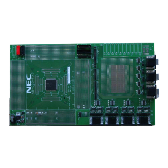
Figure 1 AB-050-FX3-U with FK3 Device
6
2 Board Description
7
Overview
7
Electrical Area
7
Figure 2-1 Board Overview
7
Functional Area
8
Connecting both Areas
8
Figure 2-2 Pin Patch Area
8
Table 2-1 Overview of Functional Signals
8
Reset
9
Nwire Connection
9
PG-FP4 Connection
9
Table 2-2 CN48 - Nwire
9
Table 2-3 FP4 (CSI) Jumpers
9
Rs-232 / Lin
10
Table 2-4 FP4 (UART) Jumpers
10
Table 2-5 Uartdn Signal Jumpers
10
Table 2-6 RS-232 Signal Jumpers
11
Table 2-7 LIN Bus Signal Jumpers
12
Can
13
Table 2-8 CAN Signal Jumpers
13
3 Mounting the FK3 Device on the Board
14
Figure 3-1 FK3 Device Mounting (1)
14
Figure 3-2 FK3 Device Mounting (2)
14
4 Connecting the Power Supply
15
5 UART / LIN CAN DSUB Connectors
16
UART / LIN Connectors
16
Figure 5-1 UART / LIN DSUB Connectors
16
Table 5-1 UART / LIN DSUB Connectors
16
CAN Connectors
17
Figure 5-2 CAN DSUB Connector
17
Table 5-2 CAN DSUB Connectors
17
6 Mounting Other Fx3 Devices on the Board
18
Mounting Devices
18
Mounting a FE3 Device
18
Figure 6-1 Mounting a FE3 Device
18
Mounting a FF3 Device
19
Mounting a FG3 Device
19
Figure 6-2 Mounting a FF3 Device
19
Figure 6-3 Mounting a FG3 Device
19
Mounting a FJ3 Device
20
Figure 6-4 Mounting a FJ3 Device
20
Pin Connection
21
Power Supply Pins
21
Figure 6-5 Device Power Supply
21
Table 6-1 VSS Signal Connection
21
REGC Pin
22
Figure 6-6 REGC Pin Components
22
Table 6-2 VDD Signal Connection
22
Table 6-3 REGC Signal Connection
22
X1, X2 Pins
23
Figure 6-7 X1, X2 Pin Components
23
Table 6-4 X1, X2 Signal Connection
23
Xt1, Flmd0
24
Figure 6-8 Pins with Pull-Down
24
Table 6-5 XT1, FLMD0 Signal Connection
24
Functional Pin Connection
25
Jumper Overview
25
Figure 6-9 Jumpers Location
25
Testpoints
26
Reset Signal
26
Figure 6-10 Test Point Location
26
Table 6-6 Colours of Jumper Functionality
26
Table 6-7 Reset Signal Connection
26
NWIRE Signals
27
Flash Programming Interface
27
Table 6-8 Nwire Interface Signals
27
Table 6-9 Flash Programming Jumper Settings
27
CAN Interface
28
Table 6-10 CAN Jumper Settings
28
UARTD Interface
29
Table 6-11 UARTD Jumper Settings
29
7 Revision History
30
8 Appendix A - Pin Number Templates
31
9 Appendix B - Schematic
32
Advertisement
Advertisement
Related Products
NEC ASLCD73VXM-BK - AccuSync - 17" LCD Monitor
NEC AccuSync AS90M
NEC ASLCD203WXM-BK - AccuSync - 20.1" LCD Monitor
NEC NEAXMail AD-64
NEC AK-824
NEC AccuSync AS271F
NEC ASLCD193WXM-BK-R
NEC ASLCD223WXM-BK-R
NEC AIT-3
NEC AP300E
NEC Categories
Monitor
Projector
Server
Telephone
Computer Hardware
More NEC Manuals
Login
Sign In
OR
Sign in with Facebook
Sign in with Google
Upload manual
Upload from disk
Upload from URL