Sign In
Upload
Manuals
Brands
Nokia Manuals
Network Hardware
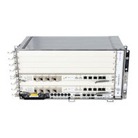
7360 ISAM FX-16
Nokia 7360 ISAM FX-16 Manuals
Manuals and User Guides for Nokia 7360 ISAM FX-16. We have
1
Nokia 7360 ISAM FX-16 manual available for free PDF download: Hardware Installation Manual
Nokia 7360 ISAM FX-16 Hardware Installation Manual (468 pages)
ANSI
Brand:
Nokia
| Category:
Network Hardware
| Size: 33.35 MB
Table of Contents
Table of Contents
3
7360 ISAM FX-16 Shelf Installation
5
7360 ISAM FX-12 Shelf Installation
9
7360 ISAM FX-8 Shelf Installation
13
1 Preface
25
Preface
25
Scope
25
Applicable Releases
25
Table 1 7360 ISAM FX Shelves
25
Related Documents
26
Audience
26
Assumed Knowledge
26
Assistance and Ordering Phone Numbers
26
Safety Information
26
Documents
26
Conventions
26
Acronyms and Initialisms
27
Special Information
27
Procedures with Options or Substeps
27
Table 2 Documentation Conventions
27
Multiple PDF Document Search
28
Overview
31
Requirements
32
2 Overview
34
Installation Environment Requirements
34
General Information on GR-3108-CORE Class 1 and Class 2 Environments
34
Table 3 Class 1 Controlled Protected Environments
34
GR-63-CORE Indoor Controlled Environmental Space
35
Table 4 Maximum Yearly Levels of Contamination - GR-63-CORE Indoor Controlled Environments
35
Equipment Description
36
Table 5 Supported Rack Configurations for 7360 ISAM FX
38
Figure 1 Vertical Mount Configuration for 7360 ISAM FX-16 in a 23 In. Rack
40
Figure 2 Vertical Mount Configuration for 7360 ISAM FX-12 in a 19 In. Rack
41
Figure 3 Vertical Mount Position for 7360 ISAM FX-8 in a 19 In. Rack
42
Figure 4 Vertical Mount Position for 7360 ISAM FX-8 in a 23 In. Rack
43
Figure 5 Horizontal Mount Position for 7360 ISAM FX-8 in a 19 In. Rack
44
Figure 6 Horizontal Mount Position for 7360 ISAM FX-8 in a 23 In. Rack
45
Figure 7 Horizontal Mount Position for 7360 ISAM FX-4 in a 19 In. Rack
46
Figure 8 Horizontal Mount Position for 7360 ISAM FX-4 in a 23 In. Rack
47
Figure 9 Vertical Mount Position for 7360 ISAM FX-4 in a 19 In. Rack
48
Figure 10 Vertical Mount Position for 7360 ISAM FX-4 in a 23 In. Rack
49
Figure 11 Vertical Mount Position for 7360 ISAM WM in a 23 In. Rack
50
Initial Site Survey
51
Installation Materials and Tools
52
Installation Procedures
53
Floor Preparation
55
Overview
55
General
55
Rack Footprints and Dimensions
55
Figure 12 7360 ISAM FX/WM ANSI 23 In. Rack Footprint and Dimensions
56
Figure 13 7360 ISAM FX/WM ANSI Sample Rack Configuration Floor Plan
56
Parts List
57
Recommended Tools
57
Procedures
57
Installing Racks
61
Overview
61
Unpacking and Inspection
61
Shelf Units
61
Separate Kits and Parts
61
Parts List
62
Recommended Tools
62
Transport Brackets
64
Installing a Rack
65
Figure 14 Transport Brackets Located on the Rear of the Rack
65
Parts List
66
Recommended Tools
66
Figure 15 Securing the Rack to the Floor (Non-Seismic Qualified Installation)
68
Figure 16 Rack Connector Plate for 7-Ft Rack
69
Figure 17 Bracing the Rack to Overhead (Example)
70
Figure 18 Securing the Rack to the Floor (Seismic-Qualified Installation)
72
Figure 19 Rack Connector Plate for 7-Ft Rack
73
Figure 20 Bracing the Rack to Overhead (Example)
74
Installing a 7360 ISAM FX-16 Shelf
77
Overview
77
5 Installing a 7360 ISAM FX-16 Shelf
78
Mounting the 7360 ISAM FX-16 Shelf in a 23 In. Rack
78
7360 ISAM FX-16 Rack Mounting Configurations
78
Table 6 Rack Mounting Configurations for 7360 ISAM FX-16 Shelf
78
Parts List
79
Figure 21 Rack Mounting Configuration 3FE 66742 AB for 7360 ISAM FX-16
79
Recommended Tools
80
Prerequisites
80
Figure 22 Mounting Locations for the 7360 ISAM FX-16
82
Figure 23 Mounting 7360 ISAM FX-16 Lower Shelf in a 23 In. Rack
83
Figure 24 Mounting 7360 ISAM FX-16 Upper Shelf in a 23 In. Rack
85
Installing a Drip Tray below a 7360 ISAM FX-16 Shelf
86
Figure 25 View of Drip Tray for 7360 ISAM FX-16
86
Figure 26 Mounting 7360 ISAM FX-16 Lower Drip Tray
87
Figure 27 Mounting 7360 ISAM FX-16 Upper Drip Tray
88
Installing a 7360 ISAM FX-16 Heat and Fiber Baffle Kit
89
Figure 28 Pre-Assembled 7360 ISAM FX-16 Heat and Fiber Baffle Kit
91
Figure 29 Mounting 7360 ISAM FX-16 Lower Heat and Fiber Baffle Kit
91
Figure 30 Mounting 7360 ISAM FX-16 Upper Heat and Fiber Baffle Kit
92
Figure 31 Fiber Management Bracket
93
Installing or Replacing the Fan Unit in a 7360 ISAM FX-16 Shelf
94
Figure 32 Fiber Management Bracket
94
Figure 33 Remove the Fan Cover
96
Figure 34 Fan Unit Handles
97
7360 ISAM FX-16 Shelf Cabling
99
Overview
99
Safety Precautions
100
Shelf Grounding Connection
101
Grounding Cable Type
101
Cable Routing and Connection
102
Figure 35 Shelf Grounding Cable Connector Locations on 7360 ISAM FX-16
102
Rack Grounding Connection
103
Figure 36 External Frame Ground Point Rear View
104
Power Cabling
105
General
105
DC Mains Battery Return Connection
105
Power Distribution Frame (PDF)
105
External Ground
105
Cable Routing
105
Power Distribution Unit
106
Figure 37 Power Distribution Unit on 7360 ISAM FX-16
106
Power Cables
107
Power Cable Type
107
Power Cable Routing and Connection
107
Figure 38 Safety Cover Label
107
Figure 39 Power Cable Routing for 7360 ISAM FX-16
108
Figure 40 Mounting of Power Cable Shoes and Safety Cover on 7360 ISAM FX- 16
109
CO External Alarm Connector
111
Figure 41 CO External Alarm Connector on 7360 ISAM FX-16
111
BITS Interface Connections
112
Figure 42 BITS Interface Connections on 7360 ISAM FX-16
112
Tod/1 Hz Connector
113
Figure 43 Tod/1 Hz Connector on 7360 ISAM FX-16
113
Remote Craft Port Connector
114
Combo Cable Connector
114
Cable Type
114
Connection/Locking
115
Cabling
115
Figure 44 Combo Cable
115
POTS and LINE MDF Cable Connector
116
MDF Cable Type
116
Figure 45 Combo Cable Connection on 7360 ISAM FX-16
116
Prerequisites
117
Figure 46 MDF Cable for 48-Line Cards
117
Figure 47 MDF Cable LINE Connection on 7360 ISAM FX-16
118
Vectoring Cable Connector
119
Figure 48 MDF Cable POTS Connection on 7360 ISAM FX-16
119
VL Cable
120
Prerequisites
120
Figure 49 VL Ports on the NDPS-B
122
Figure 50 Inserting the Cable Connector into a VL Port on the NDPS-B Card
123
Figure 51 VL Cable Exit Areas
124
Installing Cards in the 7360 ISAM FX-16 Shelf
125
Overview
125
Shelf Areas and Slot Positions
125
Dummy Front Panels
126
Figure 52 NT and LT Slot Positions in 7360 ISAM FX-16
126
NT Dummy Front Panel
127
NTIO Dummy Front Panel
127
Figure 53 Dummy Front Panel for NT Card
127
Dummy Front Panel for Optical LT Cards
128
Figure 54 Universal Dummy Front Panel for NTIO Card
128
Figure 55 Dummy Front Panel for Optical LT Card
128
Recommended Tools
129
Guideline for Card Installation
129
Installation Procedures
130
General
130
Rules for Handling Cards
131
ESD Sensitive Cards
131
Figure 56 ESD Awareness Symbol
132
Figure 57 Label for Earth Bonding Point
132
Cards with Optical Fiber Connectors
133
Figure 58 Laser Classification Label
133
Figure 59 NT Card Slots in 7360 ISAM FX-16
134
Figure 60 NTIO Slot
136
Figure 61 LT Card Slots in 7360 ISAM FX-16
137
Figure 62 Ejector Handles for LT Cards
139
Figure 63 Ejector Handles for LT Cards
139
Figure 64 Ejector Handles for NT Cards
139
Fiber Optic Cable Management in the 7360 ISAM FX-16 Shelf
141
Overview
141
Managing Fiber Optic Cables
142
Figure 65 Fiber Guiding Elements of the 7360 ISAM FX-16 Optical Fiber Management Kit
142
General Safety and Operations Information
143
Optical Modules
143
Fiber Cables
144
Routing Fiber Optic Cables in the Rack
144
Fiber Management Kit
144
Routing Fiber Optic Cables
145
Figure 66 Fiber Management Guide for 7360 ISAM FX-16
145
Figure 67 Fiber Routing with a Fiber Management Guide for 7360 ISAM FX-16
145
Figure 68 Fiber Routing Without a Fiber Management Guide for 7360 ISAM FX- 16
146
Figure 69 Alignment of 7360 ISAM FX-16 Fiber Management Guide
147
Figure 70 Mount the 7360 ISAM FX-16 Fiber Management Guide
147
Installing a 7360 ISAM FX-12 Shelf
153
Overview
153
9 Installing a 7360 ISAM FX-12 Shelf
154
Mounting the 7360 ISAM FX-12 Shelf
154
7360 ISAM FX-12 Rack Mounting Configurations
154
Parts List
154
Table 7 Vertical Mounting Configurations for 7360 ISAM FX-12 in a Seismic 19 In. Rack
154
Recommended Tools
155
Figure 71 Vertical Mounting Locations in a 19 In. Rack for 7360 ISAM FX-12
156
Installing a 7360 ISAM FX-12 Heat and Fiber Baffle Kit
157
Figure 72 Pre-Assembled Upper Baffle Assembly of the 7360 ISAM
159
Heat and Fiber Baffle Kit
159
Figure 73 Mounting the Upper Baffle Assembly - Lower Shelf
160
Figure 74 Mounting the Lower Baffle - Lower Shelf
161
Figure 75 Mounting the Upper Baffle Assembly - Upper Shelf
162
Figure 76 Mounting the Lower Baffle - Upper Shelf
163
Replacing the Fan Unit in a 7360 ISAM FX-12 Shelf
164
Figure 77 Remove the Fan Cover
166
Figure 78 Fan Unit Handles
167
7360 ISAM FX-12 Shelf Cabling
169
Overview
169
Safety Precautions
170
Shelf Grounding Connection
170
Grounding Cable Type
171
Cable Routing and Connection
171
10 7360 ISAM FX-12 Shelf Cabling
172
Grounding Cable Connection on 7360 ISAM FX-12
172
Rack Grounding Connection
173
Power Cabling
174
External Frame Ground Point Rear View
174
General
175
Power Distribution Frame (PDF)
175
External Ground
175
Cable Routing
175
Power Distribution Unit
175
Power Cables
176
Power Cable Type
176
Power Cable Routing and Connection
176
Power Cable Routing for 7360 ISAM FX-12
177
Mounting of Power Cable Shoes and Safety Cover on 7360 ISAM FX- 12
178
CO Alarm Connector
179
External Interfaces on 7360 ISAM FX-12
179
BITS Interface Connections
180
CO External Alarm Cable for 7360 ISAM FX-12
180
Tod/Pps Connector
181
Remote Craft Port Connector
181
Combo Cable Connector
181
Tod/Pps Connector Location on NT Card
181
Cable Type
182
Connection/Locking
182
Cabling
182
Combo Cable
182
POTS and LINE MDF Cable Connector
183
MDF Cable Type
183
Combo Cable Connection on 7360 ISAM FX-12
183
Prerequisites
184
MDF Cable for 48-Line Cards
184
MDF Cable LINE Connection on 7360 ISAM FX-12
185
Vectoring Cable Connector
186
MDF Cable POTS Connection on 7360 ISAM FX-12
186
VL Cable
187
Prerequisites
187
VL Ports on the NDPS-B
189
Inserting the Cable Connector into a VL Port on the NDPS-B Card
190
VL Cable Exit Areas
190
Installing Cards in the 7360 ISAM FX-12 Shelf
193
Overview
193
Shelf Areas and Slot Positions
193
11 Installing Cards in the 7360 ISAM FX-12 Shelf
194
Dummy Front Panels
194
NT Dummy Front Panel
194
LT and NT Slot Positions on 7360 ISAM FX-12
194
NTIO Dummy Front Panel
195
Dummy Front Panel for NT Card
195
Dummy Front Panel for Optical LT Cards
196
Universal Dummy Front Panel for NTIO Card
196
Dummy Front Panel for Optical LT Card
196
Recommended Tools
197
Guideline for Card Installation
197
Installation Procedures
198
General
198
Rules for Handling Cards
199
ESD Sensitive Cards
199
ESD Awareness Symbol
200
Cards with Optical Fiber Connectors
201
Location of Earth Bonding Point
201
Laser Classification Label
202
NT Card Slots in 7360 ISAM FX-12
203
NTIO Slot
205
LT Cards Slots in 7360 ISAM FX-12
206
Ejector Handles for LT Cards
207
Ejector Handles for NT Cards
208
Remove Safety Cover and Power Cable Shoes on 7360 ISAM FX-12
209
Remove Fixation Screws for NGFC-I Card
210
Fiber Optic Cable Management in the 7360 ISAM FX-12 Shelf
211
Overview
211
12 Fiber Optic Cable Management in the 7360 ISAM FX-12
212
Fiber Management Bracket for 7360 ISAM FX-12
212
Fiber Management Guide for 7360 ISAM FX-12
212
Managing Fiber Optic Cables
213
Upper Baffle Assembly for 7360 ISAM FX-12 Vertical Rack Mounting Configurations
213
General Safety and Operations Information
214
Optical Modules
214
Fiber Cables
215
Fiber Management Guides
215
Routing Fiber Optic Cables
215
Mounting of 7360 ISAM FX-12 Fiber Management Guide
216
Alignment of 7360 ISAM FX-12 Fiber Management Guide
217
Mounting of 7360 ISAM FX-12 Fiber Management Guide
217
Installing a 7360 ISAM FX-8 Shelf
223
Overview
223
Mounting the 7360 ISAM FX-8 Shelf in a 19 In. Rack
224
Mount for 7360 ISAM FX-8
224
7360 ISAM FX-8 Rack Mounting Configurations
225
13 Installing a 7360 ISAM FX-8 Shelf
226
13 Installing a 7360 ISAM FX-8 Shelf
226
Horizontal Mounting Configuration for 7360 ISAM FX-8 in a 19 in
226
EIA Standard Rack
226
Table 9 Vertical Mounting Configurations for 7360 ISAM FX-8 in a 19 in
226
Vertical Mounting Configuration for 7360 ISAM FX-8 in a 19 In. EIA Standard Rack
227
Parts List
228
Recommended Tools
228
Figure 117 Horizontal Mounting Locations in a 19 In. Rack for 7360 ISAM FX-8
230
Figure 118 Vertical Mounting Locations in a 19 In. Rack for the 7360 ISAM FX-8
232
Figure 119 Mounting the 7360 ISAM FX-8 Pre-Assembled Shelf Mounting Bracket and Air Intake Baffle/Drip Tray in a 19 In. Rack
233
Figure 120 Location of 7360 ISAM FX-8 Top Mounting Bracket
234
Figure 121 Mounting the 7360 ISAM FX-8 Pre-Assembled Skirts and Bracket
235
Figure 122 Mounting the 7360 ISAM FX-8 Intumescent Panel Onto the Skirt Assembly
236
Figure 123 Mounting the 7360 ISAM FX-8 Top Baffle
237
Figure 124 Attaching the 7360 ISAM FX-8 Bottom Mounting Bracket in a 19 In.rack
238
Figure 125 Mounting the 7360 ISAM FX-8 Shelf Assembly Vertically in a 19 in
239
Rack
239
Mounting the 7360 ISAM FX-8 Shelf in a 23 In. Rack
240
7360 ISAM FX-8 Rack Mounting Configurations
240
Rack
240
Table 10 Horizontal Mounting Configuration Supported in a 23 In. Rack for
240
Figure 126 Horizontal Mounting Configuration in a 23 In. Rack for
241
7360 Isam Fx-8
241
Table 11 Vertical Mounting Configuration for 7360 ISAM FX-8 in a 23 In. Rack
242
Parts List
243
Figure 127 Vertical Mounting Configuration for 7360 ISAM FX-8 in a 23 In. Rack
243
Rack
243
Figure 128 Horizontal Mounting Locations for 7360 ISAM FX-8 in a 23 In. Rack
245
Figure 129 Horizontal Mounting Installation for 7360 ISAM FX-8 in a 23 In. Rack
246
Figure 130 Veritcal Mounting Locations for 7360 ISAM FX-8 in a 23 In. Rack
248
Figure 131 Mounting the 7360 ISAM FX-8 Rack Adapter Brackets to a 23 In. Rack
249
Figure 132 Mounting the 7360 ISAM FX-8 Pre-Assembled Shelf Mounting Bracket and Air Intake Baffle/Drip Tray in a 23 In. Rack
250
Figure 133 Attaching the 7360 ISAM FX-8 Bottom Mounting Bracket in a 23 In. Rack
251
Installing or Replacing a Fan Unit in a 7360 ISAM FX-8 Shelf
252
Figure 134 Mounting the 7360 ISAM FX-8 Shelf Assembly Vertically in a 23 in
252
Rack
252
Figure 135 Fan Installation for 7360 ISAM FX-8
255
7360 ISAM FX-8 Shelf Cabling
259
Overview
259
Safety Precautions
260
Shelf Grounding Connection
260
Grounding Cable Type
261
Cable Routing and Connection
261
Figure 136 Grounding Cable Connection on 7360 ISAM FX-8
262
Rack Grounding Connection
263
Power Cabling
264
Figure 137 External Frame Ground Point Rear View
264
General
265
Power Distribution Frame (PDF)
265
External Ground
265
Cable Routing
265
Power Distribution Unit
265
Power Cables
266
Power Cable Type
266
Power Cable Routing and Connection
266
Figure 138 Power Cable Routing for 7360 ISAM FX-8
267
Figure 139 Mounting of Power Cable Shoes and Safety Cover on 7360 ISAM FX- 8
268
CO Alarm Connector
269
Figure 140 External Interfaces on 7360 ISAM FX-8
269
BITS Interface Connections
270
Figure 141 CO External Alarm Cable for 7360 ISAM FX-8
270
Tod/Pps Connector
271
Remote Craft Port Connector
271
Combo Cable Connector
271
Figure 142 Tod/Pps Connector Location on NT Card
271
Cable Type
272
Connection/Locking
272
Cabling
272
Figure 143 Combo Cable
272
POTS and LINE MDF Cable Connector
273
MDF Cable Type
273
Figure 144 Combo Cable Connection on 7360 ISAM FX-8
273
Prerequisites
274
Figure 145 MDF Cable for 48-Line Cards
274
Figure 146 MDF Cable LINE Connection on 7360 ISAM FX-8
275
Vectoring Cable Connector
276
Figure 147 MDF Cable POTS Connection on 7360 ISAM FX-8
276
VL Cable
277
Prerequisites
277
Figure 148 VL Ports on the NDPS-B
279
Figure 149 Inserting the Cable Connector into a VL Port on the NDPS-B Card
280
Figure 150 VL Cable Exit Areas
281
Installing Cards in the 7360 ISAM FX-8 Shelf
283
Overview
283
Shelf Areas and Slot Positions
283
Dummy Front Panels
284
NT Dummy Front Panel
284
Figure 151 LT and NT Slot Positions on 7360 ISAM FX-8
284
NTIO Dummy Front Panel
285
Figure 152 Dummy Front Panel for NT Card
285
Dummy Front Panel for Optical LT Cards
286
Figure 153 Universal Dummy Front Panel for NTIO Card
286
Figure 154 Dummy Front Panel for Optical LT Card
286
Recommended Tools
287
Guideline for Card Installation
287
Installation Procedures
288
General
288
Rules for Handling Cards
289
ESD Sensitive Cards
289
Figure 155 ESD Awareness Symbol
290
Cards with Optical Fiber Connectors
291
Figure 156 Label for Earth Bonding Point
291
Figure 157 Laser Classification Label
292
Figure 158 NTIO Slot
292
Figure 159 NT Card Slots in 7360 ISAM FX-8
294
Figure 160 LT Cards Slots in 7360 ISAM FX-8
296
Figure 161 Ejector Handles for LT Cards
297
Figure 162 Ejector Handles for LT Cards
298
Figure 163 Ejector Handles for NT Cards
298
Figure 164 Remove Safety Cover and Power Cable Shoes on 7360 ISAM FX-8
299
Figure 165 Remove Fixation Screws for NGFC-H Card
300
Fiber Optic Cable Management in the 7360 ISAM FX-8 Shelf
301
Overview
301
Managing Fiber Optic Cables
302
Figure 166 Fiber Management Kit for 7360 ISAM FX-8
302
Figure 167 Baffle for 7360 ISAM FX-8 Vertical Rack Mounting Configurations
302
General Safety and Operations Information
303
Optical Modules
303
Fiber Cables
304
Figure 168 Mounting of 7360 ISAM FX-8 Fiber Management Kit
305
Figure 169 Alignment of 7360 ISAM FX-8 Fiber Management Guide
306
Figure 170 Mount the 7360 ISAM FX-8 Fiber Management Guide
306
Installing a 7360 ISAM FX-4 Shelf
311
Figure 171 19 In. EIA Standard Rack Upright Channel Direction in Horizontal
312
Mount for 7360 ISAM FX-4
312
ISAM FX-4 Rack Mounting Configurations
313
17 Installing a 7360 ISAM FX-4 Shelf
314
Figure 172 Horizontal Mounting Configuration for 7360 ISAM FX-4 in a 19 in
314
EIA Standard Rack
314
Table 13 Vertical Mounting Configurations for 7360 ISAM FX-4 in a 19 in
314
Figure 173 Vertical Mounting Configuration for 7360 ISAM FX-4 in a 19 In. EIA Standard Rack
315
Parts List
316
Figure 174 Horizontal Mounting Locations in a 19 In. Rack for 7360 ISAM FX-4
318
Figure 175 Vertical Mounting Locations for the 7360 ISAM FX-4 in a 19 In. Rack
320
Figure 176 Mounting the 7360 ISAM FX-4 Pre-Assembled Shelf Mounting Bracket and Air Intake Baffle/Drip Tray in a 19 In. Rack
321
Figure 177 Location of 7360 ISAM FX-4 Top and Bottom Mounting Brackets
322
Figure 178 Mounting the 7360 ISAM FX-4 Pre-Assembled Skirts and Bracket
323
Figure 179 Mounting the 7360 ISAM FX-4 Intumescent Panel Onto the Skirt Assembly
324
Figure 180 Mounting the 7360 ISAM FX-4 Top Baffle
325
Figure 181 Attaching the 7360 ISAM FX-4 Bottom Mounting Bracket in a 19 In. Rack
326
Figure 182 Mounting the 7360 ISAM FX-4 Shelf Assembly Vertically in a 19 in
327
Rack
327
Rack
328
Table 14 23 In. Rack Horizontal Mounting Configuration for 7360 ISAM FX-4
328
ISAM FX-4 Rack Mounting Configurations
328
Figure 183 23 In. Rack Horizontal Mounting Configuration for 7360 ISAM FX-4
329
Table 15 Vertical Mounting Configuration for 7360 ISAM FX-4 23 In. Rack
329
Figure 184 Vertical Mounting Configuration for 7360 ISAM FX-4 in a 23 In. Rack
330
Parts List
331
Figure 185 Horizontal Mounting Locations for 7360 ISAM FX-4 in a 23 In. Rack
332
Figure 186 Horizontal Mounting Installation for 7360 ISAM FX-4 in a 23 In. Rack
333
Figure 187 Vertical Mount Locations for the 7360 ISAM FX-4 in a 23 In. Rack
335
Figure 188 Mounting the 7360 ISAM FX-4 Rack Adapter Brackets to a 23 In. Rack
336
Figure 189 Mounting the 7360 ISAM FX-4 Pre-Assembled Shelf Mounting Bracket and Air Intake Baffle/Drip Tray in a 23 I N. Rack
337
Figure 190 Attaching the 7360 ISAM FX-4 Bottom Mounting Bracket in a 23 In. Rack
338
Figure 191 Mounting the 7360 ISAM FX-4 Shelf Assembly Vertically in a 23 in
339
Rack
339
Figure 192 Fan Installation for 7360 ISAM FX-4 Shelf
341
7360 ISAM FX-4 Shelf Cabling
343
Safety Precautions
344
Grounding Cable Type
345
Figure 193 Grounding Cable Connection on 7360 ISAM FX-4
346
Rack Grounding Connection
347
Figure 194 External Frame Ground Point Rear View
348
Power Cabling
348
General
349
Figure 195 Power Distribution Unit on 7360 ISAM FX-4
350
Power Cables
350
Figure 196 Power Cable Routing for 7360 ISAM FX-4
351
Power Cable Routing and Connection
351
7360 Isam Fx-4
352
Figure 197 Mounting of Power Cable Screws and Safety Cover on
352
CO External Alarm Connector
353
Figure 198 External Interfaces on 7360 ISAM FX-4
353
BITS Interface Connections
354
Figure 199 External CO Alarm Cable for 7360 ISAM FX-4
354
Figure 200 Tod/Pps Connector Location on NT Card
355
Remote Craft Port Connector
355
Connection/Locking
356
Figure 201 Combo Cable
356
Figure 202 Combo Cable Connection on 7360 ISAM FX-4
357
POTS and LINE MDF Cable Connector
357
Figure 203 MDF Cable for 48-Line Cards
358
Prerequisites
358
Figure 204 MDF Cable LINE Connection on 7360 ISAM FX-4
359
Figure 205 MDF Cable POTS Connection on 7360 ISAM FX-4
359
Vectoring Cable Connector
360
Figure 206 VL Ports on the NDPS-B
362
Figure 207 Inserting the Cable Connector into a VL Port on the NDPS-B Card
363
Figure 208 VL Cable Exit Areas
364
Installing Cards in the 7360 ISAM FX-4 Shelf
365
Figure 209 NT and LT Slot Positions in 7360 ISAM FX-4
365
Dummy Front Panels
366
Figure 210 Dummy Front Panel for NT Card
367
Figure 211 Universal Dummy Front Panel for NTIO Card
368
Figure 212 Dummy Front Panel for Optical LT Card
368
Recommended Tools
369
Installation Procedures
370
Rules for Handling Cards
371
Figure 213 ESD Awareness Symbol
372
Figure 214 Label for Earth Bonding Point
373
Cards with Optical Fiber Connectors
373
Figure 215 Laser Classification Label
374
Figure 216 NTIO Slot
374
Figure 217 NT Card Slots in 7360 ISAM FX-4
376
Figure 218 LT Card Slots in 7360 ISAM FX-4
378
Figure 219 Ejector Handles for LT Cards
379
Figure 220 Ejector Handles for LT Cards
380
Figure 221 Ejector Handles for NT Cards
380
Figure 222 Remove Safety Cover and Power Cable Screws on 7360 ISAM FX-4
381
Figure 223 Remove Fixation Screws for NGFC-G Card
381
Fiber Optic Cable Management in the 7360 ISAM FX-4 Shelf
383
Figure 224 Fiber Management Kit for 7360 ISAM FX-4
384
Figure 225 Baffle for 7360 ISAM FX-4 Vertical Rack Mounting Configurations
384
Managing Fiber Optic Cables
384
General Safety and Operations Information
385
Fiber Cables
386
Figure 226 Mounting of the 7360 ISAM FX-4 Fiber Management Kit
387
Figure 227 Alignment of 7360 ISAM FX-4 Fiber Management Guide
388
Figure 228 Mount the 7360 ISAM FX-4 Fiber Management Guide
388
Installing a 7360 ISAM WM Shelf
393
View of Drip Tray for 7360 ISAM WM
393
Mounting 7360 ISAM WM Drip Tray
395
ISAM WM Rack Mounting
396
Table 16 Supported Rack Configuration with the 7360 ISAM WM Shelf
397
21 Installing a 7360 ISAM WM Shelf
397
In. Rack Vertical Mounting Configuration for 7360 ISAM WM
398
Parts List
398
Recommended Tools
399
Mounting a 7360 ISAM WM in a 23 In. Rack
401
Attaching the 7360 ISAM WM Shelf to the Rack
403
7360 ISAM WM Shelf Cabling
405
Safety Precautions
406
Grounding Cable Type
407
Shelf Grounding Cable Connector Location on 7360 ISAM WM
407
Rack Grounding Connection
408
External Frame Ground Point Rear View
409
Power Distribution on the 7360 ISAM WM Shelf
410
Power Cable
410
22 7360 ISAM WM Shelf Cabling
411
7360 ISAM WM Power Cable
411
Table 17 Supported 7360 ISAM WM Power Cable
411
7360 ISAM FX-16 Shelf
412
Power Cable Routing from the 7360 ISAM WM to the 7360 ISAM FX- 16 Shelf
413
Figure 240 Routing the Power Cable
414
Routing the Power Cable
414
Connecting the Power Cable
415
Alarm Cable
415
7360 ISAM WM Alarm Cable
416
Alarm Cable Routing Connection
416
CO External Alarm Connector on 7360 ISAM WM
417
Installing Cards in the 7360 ISAM WM Shelf
419
Card Slot Positions on 7360 ISAM WM
420
Dummy Front Panels
420
Dummy Front Panel for 7360 ISAM WM Line Card Slots
421
Dummy Front Panel for 7360 ISAM WM Power Card Slots
421
Dummy Front Panel with Pre-Cabling for 7360 ISAM WM Line Card Slots
421
Guideline for Card Installation
422
General
423
ESD Awareness Symbol
424
Label for Earth Bonding Point
424
Cards with Optical Fiber Connectors
425
Laser Caution Label
425
7360 ISAM WM Power Card Slots
426
Ejector Handles for 7360 ISAM WM Cards
426
7360 ISAM WM Controller Card Slot
427
7360 ISAM WM Line Card Slots
428
Shelf
431
Fiber Optic Cable Management in the 7360 ISAM WM Shelf
431
Overview
431
Management Kit
432
Managing Fiber Optic Cables
432
Optical Modules
433
Fiber Management Guide for 7360 ISAM WM
434
Routing Fiber Optic Cables
434
Alignment of 7360 ISAM WM Fiber Management Guide
435
Fiber Routing with a Fiber Management Guide for the
435
7360 Isam Wm
435
Mount the 7360 ISAM WM Fiber Management Guide
436
Connector Pinning of the External Interfaces
441
25 Connector Pinning of the External Interfaces
442
Table 18 BITS Interface Pinning for 7360 ISAM FX-4, 7360 ISAM FX-8, and 7360 ISAM FX 12
442
Table 19 BITS Interface Pinning for 7360 ISAM FX-16
442
Table 20 Tod/1 Hz Pinning for the 7360 ISAM FX-16
442
Tod/1 Hz Connector
442
Table 21 Remote Craft Port Pinning for 7360 ISAM FX Shelves
443
Table 22 External Alarm Cable
444
Table 23 CO External Alarm Pinning for 7360 ISAM FX-16
444
Table 24 CO External Alarm Pinning for 7360 ISAM WM
447
MDF CHAMP100 Cable Connector
449
Table 25 Cable Color Designations
449
Line Number
450
Table 26 Wiring List for CHAMP100 MDF Cable
450
26 Connector Pinning on NT Card
453
Connector Pinning on NT Card
453
Table 27 1PPS-TTL Interface Signal List
453
Table 28 10 Mhz GPS Interface Signal List
454
Table 29 Tod/Pps Signal List and Pinning
454
Tod/Pps Interface Signal
454
Table 30 Local Craft Interface Signal List and Pinning
455
Fiber Optic Handling and Acceptance Criteria
457
Parts of a Fiber Optic Cable
458
Handling Considerations
458
Acceptance Criteria
459
27 Fiber Optic Handling and Acceptance Criteria
460
Single-Mode End-Face Zones
460
Table 31 Single-Mode End-Face Inspection Acceptance Criteria
460
Preferred Condition of Fiber Optic End-Face
461
Table 32 Acceptable and Unacceptable Conditions for Fiber Optic End-Faces
461
Fiber Optic Jumper Cable Care
462
Advertisement
Advertisement
Related Products
Nokia FPS-8
Nokia Flexi Zone Pico
Nokia Flexi BTS Series
Nokia F8T001_v1
Nokia fold 6600
Nokia FastMile
Nokia FNE32GV210
Nokia FNE43GV210
Nokia FNA43GV210
Nokia Flip 2720
Nokia Categories
Cell Phone
Headsets
Transceiver
Telephone
Handhelds
More Nokia Manuals
Login
Sign In
OR
Sign in with Facebook
Sign in with Google
Upload manual
Upload from disk
Upload from URL