Sign In
Upload
Manuals
Brands
Panasonic Manuals
Smoke Alarm
EBL512 G3 5000
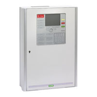
Panasonic EBL512 G3 5000 Manuals
Manuals and User Guides for Panasonic EBL512 G3 5000. We have
5
Panasonic EBL512 G3 5000 manuals available for free PDF download: Planning Manual, Planning Instructions, Operating Instructions Manual, User Manual, Information
Panasonic EBL512 G3 5000 Planning Instructions (168 pages)
Fire alarm system
Brand:
Panasonic
| Category:
Control Unit
| Size: 3.03 MB
Table of Contents
Table of Contents
3
Introduction
11
Definitions / Explanations
13
Pewn Ab
13
Alarm Points
13
Smoke Detector
13
Sensor
13
Analog Detector
13
Analog (Sensor) Base (ASB)
13
Conventional Detector
13
Conventional Detector) Base (CDB)
13
Addressable
13
Conventional Zone Line Input / External Line
14
Output Unit
14
Output / Control Output
14
Short Circuit Isolator (ISO)
14
Display Unit (D.U.)
14
COM Loop
14
Control Unit / C.U. / C.I.E
14
Fire Brigade Panel (FBP)
14
Control Panel (CP)
14
System
14
Network / TLON / Lonworks / Echelon / Node / TLON Conn. Board / Channel / Backbone Net / Router / Repeater
15
Led
15
External Indicator (Ext. LED)
15
Display / LCD
15
Door Open (Door / Key Switch)
15
Site Specific Data (SSD)
16
Software (S/W) / System Program
16
Mixed System
16
Overview
17
The EBL512 G3 System
17
Printer
17
Expansion Boards
17
Power Supply
17
S/W Versions
18
Documents
18
Applications
18
PC Software (S/W)
18
Win512 Version 2.7.X
18
Wing3 Version 1.1.X
19
TLON Manager
19
Web512 II Config Tool 2.7
19
Control Unit / TLON Network
20
The TLON Network
20
Single TLON Network / Redundancy in Distributed System
20
Control Units 5000 and 5001
22
Mounting Plates
24
Mounting Plate for 19" Mounting Rack, 5020
24
Mounting Plate for Inflammable Wall, 5021
24
COM Loops
25
Programmable Voltage Outputs (S0-S3)
27
Programmable Relay Outputs (R0-R1)
27
Programmable Inputs (I0-I3)
27
Relay Outputs for Routing Equipment (Tx)
28
Fire Alarm Output
28
Fault Condition Output
28
Expansion Boards 458X
29
Expansion Board No. (Address) Setting
30
Zones Expansion Board 4580
30
Type of Detectors = Type of Zone Line Input
31
Input States
31
Relays Expansion Board 4581
33
I/O Matrix Board 4582
33
Generic
34
Fan Control
35
Zone Control
36
Inputs and Outputs Expansion Board 4583
36
External FBP / du Interface Board 1587
36
Printer
37
TLON Connection Board 1590
38
Single TLON Network
38
Network Programming
38
Peripheral Devices
39
COM Loop Units
39
Input Units
41
Addressable I/O Units
48
Alarm Devices (Addressable Sounders)
50
Short Circuit Isolators (Addressable)
51
Units for Hazardous (Ex) Areas
52
Other COM Loop Units
53
Units Connected to the RS485 Interface
55
External Fire Brigade Panels
55
Alert Annunciation Units
57
External Presentation Units
58
Units Connected to the RS232 Interface J7
59
Web-Servers
59
Other Units
59
Alert Annunciation Controllers
59
External LED
60
Alarm Devices (Sounders, Etc.)
60
Door Release Magnets
60
Boxes
61
Duct Detector Chambers
61
Programmable Inputs
62
The 3361 Unit's Inputs In0 / Z & In1
62
Input In0
62
Input In1
62
Input Programming
63
Trigger Conditions
63
Logic
65
Programmable Outputs
66
Control Unit Outputs S0 - S3
67
Control Unit Outputs R0 & R1
67
Relays Expansion Board 4581 Output 0 - Output 7
67
The 3361 Unit's Outputs Re0 & Re1
68
The 3364 Unit's VO0 - VO2
68
The 3377 Unit's Output (Siren)
68
The 3379 Unit's Output (Sounder)
68
The 4380 Unit's Output (Beacon)
68
Output Programming
69
Type of Output
69
Logic
70
Supervised / Not Supervised
70
Time Activation Output
70
Control Expression
73
Trigger Conditions
73
Logical Operators
77
Control Expression Examples
77
Interlocking Function
81
Programming of Interlocking Function
81
Interlocking Output
81
Interlocking Input
81
Interlocking Combination
81
Interlocking Indications
83
Information of Interlocking Combinations (H9)
83
Display Interlocking Information (H9/C1)
83
Activate Interlocking Output (H9/C2)
83
Reset Interlocking Output (H9/C3)
84
Disable Interlocking Output (H9/C4)
84
Re-Enable Interlocking Output (H9/C5)
84
Interlocking Control Expressions
84
Fire Door Closing
85
Functions / Services / Features
86
Sensor Value
86
Week Average Sensor Value
86
Decision Value
87
Alarm Algorithms for Smoke Detectors / Detection Levels / Offsets
87
Alarm Algorithm / Alternative Alarm Algorithm
88
Filtering Algorithm
89
Smouldering Smoke Algorithm
91
Performance Factor
92
Algorithms for Analog Heat Detectors
93
Class A1 Algorithm
94
Class A2 S Algorithm
94
Self Verification
94
Class B S Algorithm
94
Minimum / Maximum Sensor Values
95
2-Zone / 2-Address Dependence (Co-Incidence Alarm)
96
2-Zone Dependence
96
2-Address (-Unit) Dependence
97
Reset of 2-Zone / 2-Address Dependence
97
Delayed Alarm
98
Alarm Verification Facility
98
Alert Annunciation
99
Alarm Acknowledgement Facility (AAF)
101
Quiet Alarm
103
Fire Alarm Type a and Fire Alarm Type B
103
Fire Alarm Type B
104
Fire Alarm Type a
104
Disable Alarm Points and Outputs
104
Disable Zone
105
Disable Zone / Address
105
Disable Control Output
105
Disable / Re-Enable Output Type
105
Disable Interlocking Output
105
Disable / Re-Enable Alarm Devices
105
Disable Outputs for Routing Equipment
106
Disconnect & Re-Connect Loop / Zone Line Input
106
External Time Channels
106
Test Mode
106
Test Alarm Devices
107
Test of Routing Equipment
107
Calibration of Supervised Outputs
107
Service Signal
107
Fault Signal (Fault Condition)
108
Alarm Texts
108
Creating the Alarm Texts Via Win512 Version 2.7.X
109
Downloading Alarm Texts to the Du:s 1728 / 1735 / 1736 and Ext. Fbp:s 1826 / 1828
110
Real Time Clock (RTC)
110
Daylight Saving Time
111
Loss of Main Power Source
111
Fault: Loss of Main Power Source
111
LCD Backlight
111
Evacuate
111
Win512 Tools Menu
112
Redundancy in Distributed System
114
Master and Slaves
114
Master Unit
114
Slave Unit
115
Several Control Units
117
Master Unit
117
Several Control Units (Slaves)
117
Special New Zealand Functions
120
Alarm Devices
120
Silence Alarm Devices (Inside Switch)
120
New Zealand FB Silence Switch (Outside Switch)
120
Battery Faults
122
FAULT: Battery
122
FAULT: Low Battery Capacity
122
Routing Equipment Isolate (Disable)
122
Acknowledged Alarm
122
Cyber Sensor Functions
124
Pulse up - down Counter
125
Pulse up - down Counter for Smoke
125
Pulse up - down Counter for Temperature
125
Fire Judgement
125
Pulse up - down Counter for Smoke & Temperature
125
Alarm Threshold Levels
126
Learning Function / Learning Conditions
126
Learning Conditions
126
Alarm Delay Time
128
Analog Data Output
129
Sensitivity Compensation
129
Self Diagnosis of Internal Devices
130
Address Setting Check
130
Control Unit Properties (Settings)
131
Control Unit Properties
131
General Data
131
Type of Control Unit
131
LED Indications by Inputs
132
Miscellaneous
132
Selective Alarm Presentation
133
Log Events
134
Log Setup
134
Control Unit Information
134
System Properties (Settings)
135
System Data
135
Logical Name
135
Alarm Delay Time
135
Main Power Loss Fault Delay Time
135
Alarm Reset
135
Door Closing by Time
136
Miscellaneous
136
LCD in Quiescent State
137
Time Channels
137
Time Activation Output
137
Door Open
138
Indication Door Open Affected by
138
Disablement of Routing Equipment
138
National Holidays
139
Alarm Algorithms
139
Classic Smoke Detectors' Properties
139
Multi Detectors' (3316 and 4300 + Decision Algorithm)
141
Properties
141
System Information
142
Alert Annunciation and Alarm Acknowledgement Facility
142
Alert Annunciation
142
Alarm Acknowledgement Facility
142
Two Zone Dependence
142
Compatibility
144
Cable Types
145
TLON Network Cables
145
COM Loop Cables
145
Ext. FBP / Display Units Cables
145
Conventional Zone Line Cables
145
Alarm Device Cables
146
Other Cables
146
COM Loop Cable Length
147
Current Consumption
150
Planning Instructions Fire Alarm System EBL512 G3, United Version 2.7
154
Power Supply
154
Charger Functions
155
Charging
155
Battery Charging Functions
155
Security Functions
155
Current Consumption Calculations
156
Rectifier (Main Power Source)
157
Battery (Second Power Source)
157
Fuses
158
Form / Table of Current Consumption
159
W Versions
160
Technical Data
161
Limitations
162
User Definable Texts
162
C.I.e. / System
162
National Regulations
164
Drawings / Connection Diagrams
165
Revision History
166
Advertisement
Panasonic EBL512 G3 5000 Planning Manual (168 pages)
Fire Alarm System
Brand:
Panasonic
| Category:
Smoke Alarm
| Size: 3.3 MB
Table of Contents
Table of Contents
3
1 Introduction
10
2 Definitions / Explanations
12
Pewn Ab
12
Alarm Points
12
Smoke Detector
12
Sensor
12
Analog Detector
12
Analog (Sensor) Base (ASB)
12
Conventional Detector
12
Conventional Detector) Base (CDB)
12
Addressable
12
Conventional Zone Line Input / External Line
13
Output Unit
13
Output / Control Output
13
Short Circuit Isolator (ISO)
13
Display Unit (D.U.)
13
COM Loop
13
Control Unit / C.U. / C.I.E
13
Fire Brigade Panel (FBP)
13
Control Panel (CP)
13
System
13
Network / TLON / Lonworks / Echelon / Node / TLON Conn. Board / Channel / Backbone Net / Router / Repeater
14
Led
14
External Indicator (Ext. LED)
14
Display / LCD
14
Door Open (Door / Key Switch)
14
Site Specific Data (SSD)
15
Software (S/W) / System Program
15
3 Overview
16
The EBL512 G3 System
16
Printer
16
Expansion Boards
16
Power Supply
16
S/W Versions
17
Documents
17
Applications
17
PC Software (S/W)
17
Wing3
17
TLON Manager
18
Webg3 Iconfig Tool
18
4 Control Unit / TLON Network
19
The TLON Network
19
Single TLON Network / Redundant TLON Network
19
5 Control Units 5000 and 5001
21
Mounting Plates
23
Mounting Plate for 19" Mounting Rack, 5020
23
Mounting Plate for Inflammable Wall, 5021
23
COM Loops
24
Programmable Voltage Outputs (S0-S3)
26
Programmable Relay Outputs (R0-R1)
26
Programmable Inputs (I0-I3)
26
Relay Outputs for Routing Equipment (Tx)
27
Fire Alarm Output
27
Fault Condition Output
27
6 Expansion Boards 458X
28
Expansion Board No. (Address) Setting
29
Zones Expansion Board 4580
29
Type of Zone Line Input
30
Input States
30
Relays Expansion Board 4581
31
Inputs and Outputs Expansion Board 4583
32
I/O Matrix Board 4582
33
Generic
34
Fan Control
35
Zone Control
36
7 Printer
37
8 TLON Connection Board 1590
38
Single TLON Network
38
Redundant TLON Network
38
Network Programming
38
9 Peripheral Devices
39
COM Loop Units
39
Input Units
41
Addressable I/O Units
48
Alarm Devices (Addressable Sounders)
50
Short Circuit Isolators (Addressable)
51
Units for Hazardous (Ex) Areas
52
Other COM Loop Units
53
COM Loop Addresses for Base Station and Wireless
56
Detectors
56
Units Connected to the RS485 Interface
56
External Fire Brigade Panels
57
Alert Annunciation Units
58
External Presentation Units
59
German Fire Brigade Panels
60
Units Connected to the RS232 Interface J7
61
Web-Servers
61
Other Units
61
Alert Annunciation Controllers
61
External LED
62
Alarm Devices (Sounders, Etc.)
62
Door Release Magnets
62
Boxes
63
Duct Detector Chambers
63
10 Programmable Inputs
64
Control Unit Inputs I0 - I3 & Inputs 0 -4 on Exp. Board 4583
65
Not Supervised
65
Supervised
65
The 3361 Unit's Inputs In0 / Z & In1
65
11 Input Programming
66
Trigger Conditions
66
Logic
69
Supervised
69
12 Programmable Outputs
70
Control Unit Outputs S0 - S3
71
Control Unit Outputs R0 & R1
72
Relays Expansion Board 4581 Output 0 - Output 7
72
Inputs and Outputs Expansion Board 4583 Output 0 & Output
72
The 3361 Unit's Outputs Re0 & Re1
72
The 3364 Unit's VO0 - VO2
73
The 3377 Unit's Output (Siren)
73
The 3379 Unit's Output (Sounder)
73
The 4380 Unit's Output (Beacon)
73
13 Output Programming
74
Type of Output
74
Logic
75
Supervised / Not Supervised
75
Output Signal Period
75
Control Expression
78
Trigger Conditions
78
Logical Operators
82
Control Expression Examples
82
14 Interlocking Function
86
Programming of Interlocking Function
86
Interlocking Output
86
Interlocking Input
86
Interlocking Combination
86
Interlocking Indications
88
Information of Interlocking Combinations (H9)
88
Display Interlocking Information (H9/C1)
88
Activate Interlocking Output (H9/C2)
89
Reset Interlocking Output (H9/C3)
89
Disable Interlocking Output (H9/C4)
89
Re-Enable Interlocking Output (H9/C5)
89
Interlocking Control Expressions
89
15 Fire Door Closing
90
16 Functions / Services / Features
91
Sensor Value
91
Week Average Sensor Value
91
Decision Value
92
Alarm Algorithms for Smoke Detectors / Detection Levels / Offsets
92
Alarm Algorithm / Alternative Alarm Algorithm
93
Filtering Algorithm
94
Smouldering Smoke Algorithm
96
Performance Factor
97
Algorithms for Analog Heat Detectors
98
Class A1 Algorithm
99
Class A2 S Algorithm
99
Self Verification
99
Class B S Algorithm
99
Minimum / Maximum Sensor Values
100
2-Zone / 2-Address Dependence (Co-Incidence Alarm)
101
2-Zone Dependence
101
2-Address (-Unit) Dependence
102
Reset of 2-Zone / 2-Address Dependence
102
Delayed Alarm
103
Alert Annunciation
104
Alarm Acknowledgement Facility (AAF)
106
Quiet Alarm
108
Fire Alarm Type a and Fire Alarm Type B
108
Fire Alarm Type B
109
Fire Alarm Type a
109
Disable Alarm Points and Outputs
109
Disable Zone
110
Disable Zone / Address
110
Disable Control Output
110
Disable / Re-Enable Output Type
110
Disable Interlocking Output
110
Disable / Re-Enable Alarm Devices
110
Disable Outputs for Routing Equipment
110
Disconnect & Re-Connect Loop / Zone Line Input
111
External Time Channels 15-63
111
Test Mode
111
Test Alarm Devices
111
Test of Routing Equipment
112
Calibration of Supervised Outputs
112
Service Signal
112
Fault Signal (Fault Condition)
113
Alarm Texts
113
Creating the Alarm Texts Via Wing3
113
Downloading Alarm Texts to the Du:s 1728 / 1735 / 1736 and Ext. Fbp:s 1826 / 1828
115
Real Time Clock (RTC)
115
Daylight Saving Time
116
Loss of Main Power Source
116
Evacuate
116
Wing3 Menu Tools
117
17 Special New Zealand Functions
119
Alarm Devices
119
Silence Alarm Devices (Inside Switch)
119
New Zealand FB Silence Switch (Outside Switch)
119
Battery Faults
121
FAULT: Battery
121
FAULT: Low Battery Capacity
121
Watchdog Reset
121
Routing Equipment Isolate (Disable)
121
Acknowledged Alarm
121
18 Cyber Sensor Functions
123
Pulse up - down Counter
124
Pulse up - down Counter for Smoke
124
Pulse up - down Counter for Temperature
124
Fire Judgement
124
Pulse up - down Counter for Smoke & Temperature
124
Alarm Threshold Levels
125
Learning Function / Learning Conditions
125
Learning Conditions
125
Alarm Delay Time
127
Analog Data Output
128
Sensitivity Compensation
128
Self Diagnosis of Internal Devices
129
Address Setting Check
129
19 Control Unit Properties
130
Control Unit Properties Dialog Box
130
General Information
130
Peripherals
130
Misc
130
Wing3 Control Unit Pop-Up Menu
131
Reset Alarm Counter
131
Software Version
131
Upgrade Number of Alarm Points
131
Restart
132
Delete
132
Properties
132
20 System Properties (Settings)
133
System Properties Dialog Box
133
Name
133
User Definable Text
133
System Properties, Page 1
133
System Properties, Page 2
135
Menu System
136
Properties
136
Time Channels
136
Alarm Algorithms
138
Output Signal Periods
140
National Holidays
141
Two Zone Dependence
142
Statistics (System Information)
143
Edit Alarm Texts
143
21 Compatibility
144
22 Cable Types
145
TLON Network Cables
145
COM Loop Cables
145
Ext. FBP / Display Units Cables
145
Conventional Zone Line Cables
145
Alarm Device Cables
146
Other Cables
146
23 COM Loop Cable Length
147
24 Current Consumption
150
25 Power Supply
154
Charger Functions
155
Charging
155
Battery Charging Functions
155
Security Functions
155
Current Consumption Calculations
156
Rectifier (Main Power Source)
157
Battery (Second Power Source)
157
Fuses
158
Form / Table of Current Consumption
158
26 W Versions
160
27 Technical Data
161
28 Limitations
162
User Definable Texts
162
C.I.e. / System
162
29 National Regulations
164
30 Drawings / Connection Diagrams
165
31 Revision History
166
Panasonic EBL512 G3 5000 Operating Instructions Manual (134 pages)
Brand:
Panasonic
| Category:
Fire Alarms
| Size: 2.86 MB
Table of Contents
Table of Contents
2
Introduction
6
Abbreviations
8
General Description
10
Ebl512 G3
12
Front
13
Fire Brigade Panel
13
Control Panel
13
Detailed Description of the Front
14
Led Indicators
15
Push Buttons
16
Display
17
Information Priority Order
18
System Information in the Lcd
19
User Definable System Information
19
User Data
20
User Name
20
Password
21
Change of Password
21
Password for Gateway Access Only
21
Access
22
How to Log on
22
Navigation / General Procedures
22
User Levels
23
User Level According to En54-2
23
User Level 1
23
User Level 2A
24
User Level 2B
24
User Level 2C
25
User Level 3A
26
Access Level 3B
26
Access Level 4
26
Technical Number
27
Presentation Number
28
Silence Alarm Devices
29
Disable or Re-Enable Alarm Devices
30
Silence Buzzer
31
Disable or Re-Enable Output
32
Disable or Re-Enable Control Outputs
33
Evacuate
34
Open Door
35
Disable Routing Equipment with Door Switch
35
Silence Buzzer with Door Switch
35
Alarm
36
Alarm Types
36
Pre-Warning
36
Fire Alarm
38
Heavy Smoke Alarm / Heavy Heat Alarm
42
Alert Annunciation Alarm (Aa Alarm)
43
Key Cabinet Alarm
44
Co-Incidence Alarm (2-Address / -Zone Dependence)
45
Delayed Alarm
46
Local Alarm Acknowledgement (Laa)
47
Quiet Alarm
48
Alarm Source
49
Alarm Reset
50
Pre-Warning Reset
50
Fire Alarm Reset
50
All
50
Single
51
Single with Automatic Disablement
52
Test Mode Alarm
52
Heavy Smoke / Heat Alarm Reset
52
Alert Annunciation
52
Key Cabinet Alarm Reset
53
Co-Incidence Alarm
53
Delayed Alarm
53
Local Alarm Acknowledgement (Laa) Reset
53
Quiet Alarm Reset
53
Fault
54
Fault Messages
56
Fault Acknowledge
76
Commissioning
77
Single Control Unit
77
Control Units in a Network
78
5040 Network
78
Tlon Network
78
Add a Control Unit into a Network
79
Make Two Networks One
80
Delete a Control Unit in a Network
80
Upgrade Number of Alarm Points
81
Control Units in a Network
81
Restart
82
Safe Shut down
82
Restart Table
83
Explanation of Restart Codes
83
During Restart
84
Memory Fault
85
Menus
86
Perform Monthly Test (H1)
87
Disable or Re-Enable (H2)
89
Zone or Zone/Address (H2/B1)
90
Output (H2/B2)
91
Output Type (H2/B3)
92
Alarm Devices (H2/B4)
93
Routing Equipment (H2/B5)
93
Alert Annunciation (H2/B6)
94
Set Calendar and Clock (H3)
95
Present System Status (H4)
96
Disablement (H4/U1)
96
Disablement by Time Channel (H4/U2)
97
Open Doors (H4/U3)
97
Sensor Values (H4/U4)
98
Explanation to the Sensor Values
99
Sensors Activating Service Signal (H4/U5)
100
Technical Warning (H4/U6)
100
Event Log (H4/U7)
101
Information (H4/U8)
102
Service (H5)
103
Calibration of Supervised Outputs (H5/A1)
104
End-Of-Line Devices
104
Sensitive Fault Detection Mode (H5/A2)
105
Service Mode for Com-Loop (H5/A3)
106
Display Current Consumption in Unit (H5/A4)
107
Display Current Consumption on Com-Loop (H5/A5)
108
Display Statistics for Communication (H5/A6)
109
Activate Address Setting Mode for du (H5/A7)
110
Setup Wireless Detectors (H5/A8)
111
Ssd Information (H5/A9)
112
Fault Acknowledge (H6)
113
Perform Zone Test (Test Mode) (H7)
114
During the Test
115
After the Test
115
Maintenance (H8)
116
Dis- / Re-Connect Loop / Zone Line Input (H8/S1)
116
Acknowledge Service Signal (H8/S2)
117
Clear Weekly Average (H8/S3)
118
Test of Alarm Devices (H8/S4)
119
Safe Shut down of Control Unit (H8/S5)
120
After Restart
121
Activate Address in Alarm Mode (H8/S6)
122
Synchronize the Control Units (H8/S7)
123
Activate / Reset Outputs (H8/S8)
124
Interlocking Outputs and Inputs (H9)
125
Activated Interlocking Outputs / Inputs (H9/C1)
125
Activate / Deactivate Interlocking Output (H9/C2)
126
Disable / Re-Enable Interlocking Output (H9/C3)
127
Change Password (H10)
128
Printer
128
How to Change Paper in the Printer
128
Replacing Tlon Board and Main Board
129
Battery Maintenance
130
How to Avoid Nuisance Fire Alarms
131
Radioactive Radiation Source
133
Advertisement
Panasonic EBL512 G3 5000 User Manual (31 pages)
Fire alarm system
Brand:
Panasonic
| Category:
Smoke Alarm
| Size: 0.71 MB
Table of Contents
Fire Alarm System
1
User Manual
1
Table of Contents
3
1 Introduction
4
2 Front
5
3 Log on to the Control Unit (C.I.e.)
6
4 Perform Monthly Test (H1)
8
5 Disable or Re-Enable (H2)
9
Zone or Zone / Address (B1)
10
Output (B2)
11
Output Type (B3)
12
Alarm Devices (B4)
13
Routing Equipment (B5)
14
Alert Annunciation Function (B6)
15
6 Set Calendar and Clock (H3)
16
7 Present System Status (H4)
17
Disablement (U1)
18
Disablement by Time Channel (U2)
18
Open Doors (U3)
19
Sensor Values (U4)
19
Sensors Activating SERVICE Signal (U5)
20
Technical Warning (U6)
20
Event Log (U7)
21
Information (U8)
21
8 FAULT Acknowledge (H6)
22
9 Perform ZONE TEST (Test Mode) (H7)
23
10 Interlocking Outputs and Inputs (H9)
25
Activated Interlocking Outputs / Inputs (C1)
26
Activate / Deactivate Interlocking Output (C2)
26
Disable / Re-Enable Interlocking Output (C3)
27
11 Change Password (H10)
28
12 Revision History
29
Panasonic EBL512 G3 5000 Information (2 pages)
Fire alarm system
Brand:
Panasonic
| Category:
Smoke Alarm
| Size: 0.15 MB
Advertisement
Related Products
Panasonic EBL512
Panasonic EBL512 G3 V1.1.x
Panasonic EBL128
Panasonic EBH655 - CONSUMER HH CELL PHONE
Panasonic EBTX320 - Cell Phone ATLAS
Panasonic EB-G450
Panasonic EB-VS6
Panasonic EB-G51M
Panasonic EB-HF450Z
Panasonic GSM EB-GD95C
Panasonic Categories
Camcorder
Air Conditioner
TV
Digital Camera
Cordless Telephone
More Panasonic Manuals
Login
Sign In
OR
Sign in with Facebook
Sign in with Google
Upload manual
Upload from disk
Upload from URL