Sign In
Upload
Manuals
Brands
panasonic Manuals
Accessories
GP-X8S
User Manuals: panasonic GP-X8S Displacement Sensor
Manuals and User Guides for panasonic GP-X8S Displacement Sensor. We have
3
panasonic GP-X8S Displacement Sensor manuals available for free PDF download: User Manual, Instruction Manual
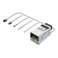
panasonic GP-X8S User Manual (154 pages)
Digital Displacement Sensor
Brand:
panasonic
| Category:
Accessories
| Size: 3.59 MB
Table of Contents
Table of Contents
4
Introduction
7
Handling Precautions
8
Checking the Packaged Components
10
Notation
10
Chapter 1 Before Starting Operation
11
Features of GP-X Series
12
Basic Configuration
13
Basic Configuration
13
BCD Output Unit (Optional)
13
Cable with Connector on One End for BCD Output Unit (Optional)
13
Controller
13
Controller Communication Unit and Link Cable (Optional)
13
Extension Cable for Sensor Head (Optional)
13
Intelligent Monitor Software (Optional)
13
Sensor Head
13
Functional Description
14
Controller
14
BCD Output Unit (Optional)
17
Controller Communication Unit (Optional)
18
External I/O
19
I/O Circuit Diagrams
20
NPN Output Type
20
PNP Output Type
21
Mounting Method
22
Mounting the Controller
22
Mounting the Sensor Head
23
Processing and Tightening the Lead Wire
24
Connection
25
Connecting the Sensor Head and Controller
25
Mounting the Option Unit
26
Flow of Configuration until Operation Is Started
28
Application Usage
28
Basic Usage
28
Flow Of Configuration Until Operation Is Started
28
Usage with Optional Unit
28
Chapter 2 Basic Knowledge about Functions
29
Displaying Operation
30
Operation Panel
30
List of Characters Displayed at Controller
31
Operation System
32
Overview of Operation System
32
How to Enter a Value
37
Measurement Function
38
Holding Measurement Function
38
Trigger Input
44
List of Factory Shipment Settings
49
Chapter 3 Basic Function Setting
51
Memory Selection
52
Memory Number Selection
52
Memory Copy Function
53
Upper and Lower Limit Value Settings
54
Setting the Upper and Lower Limit Value Entry Method
54
Value Entry Setting (Direct Value Entry)
55
Using the Actual Detection Value to Set (Teaching)
56
Averaging Frequency Setting
57
Setting According to Application (Application Mode)
58
Selecting the Application Mode
58
Manual Mode
60
Press BDC Detection Mode
61
Rotation/Eccentricity Detection Mode
63
Height Detection Mode
66
Trigger Input Setting
69
External Trigger Setting
70
Internal Trigger Setting
70
Cyclic Trigger Setting
71
Comparison with Previous Mean
72
Chapter 4 Detail Setting (SET-1)
75
Selection of Object to be Detected
76
Three-Point Calibration (Linearity Adjustment)
77
Judgment Output Setting
79
Judgment Hysteresis
79
Output Style Selection
79
Output Delay
80
Display Scale
82
One-Point Scaling
82
Two-Point Scaling
84
INV Function
86
Analog Voltage Output Scale
87
One-Point Scaling
87
Two-Point Scaling
89
INV Function
91
Display Setting
92
Selection of Data Displayed in Upper and Lower Lines
92
Lower Lines
92
Selecting the Display Unit
93
Power Saving Mode Setting
94
Display Refreshment Period Menu and Display Places Setting
95
Display Places Setting
95
Interference Prevention Setting
96
Memory Switching Method Setting
99
Initialization to Factory Shipment Setting
100
Panel Key Lock
101
Chapter 5 Special Setting (SET. OP)
103
RS-232C Communication Setting
104
Communication Specification Item
104
Setting Procedure
104
Communication Specification Item
104
Connector Pin Layout on Controller Side
105
Settings Related to BCD Output Unit (Optional)
106
Overview of Specifications of BCD Output Unit
106
Overview of Specifications of BCD Output Unit
106
BCD Output Selection Procedure
108
Settings Related to Controller Communication Unit (Optional)
109
Overview of Controller Communication Unit
109
Connection of Controller Communication Unit and Address Setting
110
Connection of Controller Communication
110
Unit and Address Setting
110
Calculation between Controllers
112
Sensor Head Replacement Setting
114
Interchangeability of Sensor Head
114
Characteristics Code Entry Procedure
114
Software Version Display Menu
116
Chapter 6 RS-232C Communication Function
117
How to Use RS-232C Commands
118
Command Lists
120
Intelligent Monitor Software (GP-Xaim) (Optional)
138
Chapter 7 What to Do Upon an Error
139
Error Indication List
140
What to Do
142
Chapter 8 Specifications and Dimensions
143
Ratings and Performance
144
Sensor Head
144
Controller
145
BCD Output Unit and Controller Communication Unit
147
Dimensions (Unit: MM)
148
Sensor Head
148
Controller
151
BCD Output Unit (Optional)
151
Controller Communication Unit (Optional)
151
Advertisement
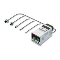
Panasonic GP-X8S User Manual (156 pages)
High-Speed High-Accuracy Eddy Current Digital Displacement Sensor
Brand:
Panasonic
| Category:
Security Sensors
| Size: 2.22 MB
Table of Contents
Table of Contents
4
Introduction
7
Handling Precautions
8
Checking the Packaged Components
10
Notation
10
Chapter 1 Before Starting Operation
11
Features of GP-X Series
12
Sensor Head
13
Controller
13
Controller Communication Unit and Link Cable (Optional)
13
BCD Output Unit (Optional)
13
Cable with Connector on One End for BCD Output Unit (Optional)
13
Extension Cable for Sensor Head (Optional)
13
Intelligent Monitor Software (Optional)
13
Functional Description
14
Controller
14
BCD Output Unit (Optional)
17
Controller Communication Unit (Optional)
18
External I/O
19
I/O Circuit Diagrams
20
NPN Output Type
20
PNP Output Type
21
Mounting Method
22
Mounting the Controller
22
Mounting the Sensor Head
23
Processing and Tightening the Lead Wire
24
Connection
25
Connecting the Sensor Head and Controller
25
Mounting the Option Unit
26
Basic Usage
28
Application Usage
28
Usage with Optional Unit
28
Chapter 2 Basic Knowledge about Functions
29
Displaying Operation
30
Operation Panel
30
List of Characters Displayed at Controller
31
Operation System
32
Overview of Operation System
32
How to Enter a Value
37
Measurement Function
38
Holding Measurement Function
38
Trigger Input
44
List of Factory Shipment Settings
49
Chapter 3 Basic Function Setting
51
Memory Selection
52
Memory Number Selection
52
Memory Copy Function
53
Upper and Lower Limit Value Settings
54
Setting the Upper and Lower Limit Value Entry Method
54
Value Entry Setting (Direct Value Entry)
54
Using the Actual Detection Value to Set (Teaching)
55
Limitations on the Setting Ranges for Upper and Lower Limit Values
56
Averaging Frequency Setting
57
Setting According to Application (Application Mode)
58
Selecting the Application Mode
58
Manual Mode
60
Press BDC Detection Mode
61
Rotation/Eccentricity Detection Mode
63
Height Detection Mode
66
Trigger Input Setting
69
External Trigger Setting
70
Internal Trigger Setting
70
Cyclic Trigger Setting
71
Comparison with Previous Mean
72
Chapter 4 Detail Setting (SET-1)
75
Selection of Object to be Detected
76
Three-Point Calibration (Linearity Adjustment)
77
Judgment Output Setting
79
Judgment Hysteresis
79
Output Style Selection
79
Output Delay
80
Display Scale
82
One-Point Scaling
82
Two-Point Scaling
84
INV Function
86
Analog Voltage Output Scale
87
One-Point Scaling
87
Two-Point Scaling
89
INV Function
91
Display Setting
92
Selection of Data Displayed in Upper and Lower Lines
92
Selecting the Display Unit
93
Power Saving Mode Setting
94
Display Refreshment Period Menu and Display Places Setting
95
Display Places Setting
95
Interference Prevention Setting
96
Memory Switching Method Setting
99
Initialization to Factory Shipment Setting
100
Panel Key Lock
101
Chapter 5 Special Setting (SET. OP)
103
RS-232C Communication Setting
104
Setting Procedure
104
Connector Pin Layout on Controller Side
105
Settings Related to BCD Output Unit (Optional)
106
Output Unit
106
BCD Output Selection Procedure
108
Settings Related to Controller Communication Unit (Optional)
109
Overview of Controller Communication Unit
109
Connection of Controller Communication Unit and Address Setting
110
Calculation between Controllers
112
Sensor Head Replacement Setting
114
Interchangeability of Sensor Head
114
Characteristics Code Entry Procedure
114
Software Version Display Menu
116
Chapter 6 RS-232C Communication Function
117
How to Use RS-232C Commands
118
Command Lists
120
Intelligent Monitor Software (GP-Xaim) (Optional)
138
Chapter 7 What to Do Upon an Error
141
Error Indication List
142
What to Do
144
Sensor Head
145
Controller
145
Ratings and Performance
146
BCD Output Unit and Controller Communication Unit
149
BCD Output Unit (Optional)
149
Dimensions (Unit: MM)
150
Sensor Head
150
Controller
153
Controller Communication Unit (Optional)
153
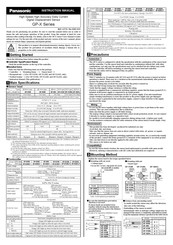
Panasonic GP-X8S Instruction Manual (2 pages)
High-Speed,High-Accuracy Eddy Current Digital Displacement Sensor
Brand:
Panasonic
| Category:
Security Sensors
| Size: 0.4 MB
Advertisement
Advertisement
Related Products
Panasonic GP-X SERIES
Panasonic GP-XC5SE
Panasonic GP-XC8S
Panasonic GP-XC10M
Panasonic GP-XC12ML
Panasonic GP-XC22KL
panasonic GP-XCP
panasonic GP-X22KL
panasonic GP-X12M12
panasonic GP-X5S
panasonic Categories
Camcorder
Air Conditioner
TV
Digital Camera
Cordless Telephone
More panasonic Manuals
Login
Sign In
OR
Sign in with Facebook
Sign in with Google
Upload manual
Upload from disk
Upload from URL