Sign In
Upload
Manuals
Brands
panasonic Manuals
All in One Printer
KX-MB2090CXW
panasonic KX-MB2090CXW Manuals
Manuals and User Guides for panasonic KX-MB2090CXW. We have
2
panasonic KX-MB2090CXW manuals available for free PDF download: Service Manual, Specifications
Panasonic KX-MB2090CXW Service Manual (276 pages)
Multi-Function printer
Brand:
Panasonic
| Category:
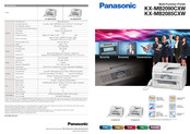
Printer
| Size: 20.97 MB
Table of Contents
Table of Contents
2
Safety Precautions
5
For Service Technicians
5
AC Caution
5
Personal Safety Precautions
6
Moving Sections of the Unit
6
Live Electrical Sections
6
Service Precautions
6
Precautions to Prevent Damage from Static Electricity
6
Warning
7
About Lead Free Solder (Pbf: Pb Free)
7
Suggested Pbf Solder
7
Discarding of P. C. Board
8
Insulation Resistance Test
8
Battery Caution
8
Laser Beam and Fuser Unit Section
8
Note for Repairing
9
Specifications
10
General/Introduction
12
Optional Accessories
12
Translation Lists
12
Features
13
General Features
13
Hardware Requirements for Multi-Function Software
13
Technical Descriptions
14
Connection Diagram
14
General Block Diagram
15
Main Board Section
17
Data Flow
17
RTC Backup Circuit
26
Modem Circuit Operation
27
TEL Line Section
27
NCU Section
29
General
29
EXT. TEL. Line Relay (RLY100)
29
Bell Detection Circuit
29
Pulse Dial Circuit
29
Line Amplifier and Side Tone Circuit
29
Calling Line Identification Circuit (FSK)
30
Calling Line Identification Circuit (DTMF)
30
Remote FAX Activation Circuit
30
TAM Interface Circuit
30
Its
31
Monitor Section
31
General
31
CIS Control Section
32
Motor Drive Section
33
Engine Motor Control Circuit
33
Scanner Motor Drive Circuit
34
Timing Chart and Wave Form of Scanner Motors
37
Normal 1-2 Phase Excitation (Half Step)
37
Flat Torque 1-2 Phase Excitation (Half Step)
38
W1-2 Phase Excitation (Quarter Step)
39
Drive Mode of FB and ADF Motor
40
FAN Motor Section
40
General
40
Circuit Diagram of FAN
41
Fan Control
41
Control Table
42
Waveform
42
Solenoid Driver Section
43
LSU (Laser Scanning Unit) Section
44
Sensors and Switches Section
46
Drum Detection
47
Pickup Sensor
47
Exit Sensor
48
Read Position Sensor
48
Registration & Manual Paper Sensor
49
Print Timing Sensor
49
Document Sensor
50
Top Cover Sensor
50
Toner Sensor
51
Handset Hook Switch
54
Operation Board Section
55
LCD Section
56
High Voltage Power Supply) Section
57
HVPS Specification
57
CHG-BIAS (Charge BIAS)/GRID/ UNIT
57
Dev DC Bias Unit
58
Dev Ac Bias Unit
58
TRA (+) BIAS (Transfer (+) BIAS)/TRA (-) BIAS (Transfer (-) BIAS) UNIT
58
Heat Lamp Control Circuit
59
Power Saving (Sleep) Function
64
Main Board Power Supply Section
65
And 1.2V Power Supply Descriptions
65
Power Supply Descriptions
65
Power Supply Descriptions
66
Power Supply Board Section
67
Mechanical Operation
68
Printing
68
Location of Controls and Components
69
Installation Instructions
69
Operating Instructions
69
Test Mode
70
Test Functions
70
DTMF Single Tone Transmit Selection
72
Button Code Table
72
Print Test Pattern
73
Service Mode
74
Programming and Lists
74
Operation
74
Operation Flow
74
Service Function Table
75
Memory Clear Specification
77
User Mode (the List below Is an Example of the SYSTEM SETUP LIST the Unit Prints Out.)
78
Service Mode Settings (Example of a Printed out List)
82
History (Example of a Printed out List)
83
Descriptions of the History Report
84
Troubleshooting Guide
85
User Recoverable Errors
85
Remote Programming
88
Entering the Remote Programming Mode and Changing Service Codes
89
Program Mode Table
90
Troubleshooting Details
94
Outline
94
Starting Troubleshooting
94
Initialization
95
Simple Check List
96
Simplified Troubleshooting Guide
97
CALL SERVICE Troubleshooting Guide
100
Print
107
Recording Paper Feed
113
Initializing Error
120
ADF (Auto Document Feeder) Section
121
Special Service Journal Reports
123
Analog Section
138
Operation Panel Section
141
Sensor Section
141
Motor Section
144
LSU Section
147
CIS Control Section
148
High Voltage Value Check Point
150
High Voltage Section
152
USB Section
157
Lan Section
161
Main Board Section
166
Power Supply Board Section
167
Recording Paper Jam
170
Service Fixture & Tools
171
Disassembly and Assembly Instructions
172
Bottom Section
173
Left Side Section
173
Operation Panel Section
174
Open Top Cover
174
Remove Operation Panel
175
Remove Operation Board
175
Remove Main Board
176
Remove Gear Chassis Section
177
Remove Right Cover
178
Remove Right Cassette Guide
178
Remove Bottom Plate
179
Remove Laser Unit
179
Remove Pick up Roller
180
Remove Low Voltage Power Board
181
Remove Mirror
181
Remove High Voltage Power Board
182
Note for Disassembly
182
Position of Installing LABEL/CIS HOME
182
Installation Position of the Lead
183
Top Cover Section (1)
183
Top Cover Section (2)
184
Bottom Part Section (1)
185
Bottom Part Section (2)
186
Side Cabinet Section (1)
187
Maintenance
188
Maintenance Items and Component Locations
188
Outline
188
Maintenance Check Items/Component Locations
188
Cleaning
190
Printing Operation Principle
190
Process Chart and Process BIAS
190
Charging
190
Exposing
191
Developing and Transcription
192
Cleaning of Transfer Roller
193
Fixing
194
Terminal Guide of the Ics Transistors and Diodes
195
Main Board
195
Operation Board
196
High Voltage Power Supply Board
196
Low Voltage Power Supply Board
196
How to Replace the Flat Package IC
197
Preparation
197
Flat Package IC Removal Procedure
197
Flat Package IC Installation Procedure
198
Bridge Modification Procedure
198
Main Board Section
199
NG Example
200
Test Chart
201
ITU-T No.1 Test Chart
201
ITU-T No.2 Test Chart
202
Schematic Diagram
203
For Schematic Diagram
203
Main Board (KX-MB2085)
204
Main Board (1)
204
Main Board (2)
206
Main Board (3)
208
Main Board (KX-MB2090)
210
Main Board (1)
210
Main Board (2)
212
Main Board (3)
214
Operation Board
216
Sensor Board
217
High Voltage Power Supply Board
218
Low Voltage Power Supply Board
219
Printed Circuit Board
220
Main Board
220
Main Board: Component View
220
Main Board: Bottom View
221
Operation Board
222
Sensor Board
223
Toner Sensor Board
223
Fuser Board
223
Pickup Sensor Board
223
Registration Sensor Board
224
Varistor Sensor Board
224
Flatbed Relay Board
224
High Voltage Power Supply Board
225
High Voltage Power Supply Board: Component View
225
High Voltage Power Supply Board: Bottom View
225
Low Voltage Power Supply Board
226
Low Voltage Power Supply Board: Component View
226
Low Voltage Power Supply Board: Bottom View
226
Exploded View and Replacement Parts List
227
Cabinet, Mechanical and Electrical Parts Location
227
Operation Panel Section
227
ADF Section
228
ADF Gear Section
229
Top Cover Section
230
Main Cabinet Section
231
Fuser Section
232
Bottom Cabinet Section (1)
233
Separation (DFP) Roller Section
234
Side Cabinet Section
235
Motor Section
236
Bottom Cabinet Section (2)
237
Output Tray Section
238
Actual Size of Screws and Washer
239
Accessories and Packing Materials
240
Electrical Parts
241
Cabinet and Electrical Parts
241
Main Board (KX-MB2085)
244
Main Board (KX-MB2090)
249
Operation Board
254
Sensor Board Parts
255
Back Light Board
256
High Voltage Power Board
256
Low Voltage Power Board
256
Advertisement
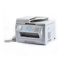
panasonic KX-MB2090CXW Specifications (2 pages)
Monochrome Laser
Brand:
panasonic
| Category:
All in One Printer
| Size: 1.4 MB
Advertisement
Related Products
Panasonic KX-MB2090ML
Panasonic KX-MB2090SX
Panasonic KX-MB2090CX
Panasonic KX-MB2000HX
PANASONIC KX-MB2000GX
PANASONIC KX-MB2025SP
Panasonic KX-MB2060C
Panasonic KX-MB2010C
Panasonic KX-MB2025CX
Panasonic KX-MB2030CX
panasonic Categories
Camcorder
Air Conditioner
TV
Digital Camera
Cordless Telephone
More panasonic Manuals
Login
Sign In
OR
Sign in with Facebook
Sign in with Google
Upload manual
Upload from disk
Upload from URL