Sign In
Upload
Manuals
Brands
Panasonic Manuals
All in One Printer
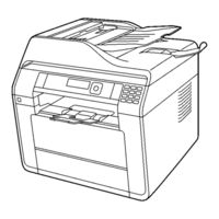
KX-MB2270JT
Panasonic KX-MB2270JT Printer Manuals
Manuals and User Guides for Panasonic KX-MB2270JT Printer. We have
1
Panasonic KX-MB2270JT Printer manual available for free PDF download: Service Manual
Panasonic KX-MB2270JT Service Manual (526 pages)
Brand:
Panasonic
| Category:
All in One Printer
| Size: 36.06 MB
Table of Contents
Table of Contents
2
1 Safety Precautions
6
For Service Technicians
6
AC Caution
6
Personal Safety Precautions
7
Moving Sections of the Unit
7
Live Electrical Sections
7
Service Precautions
7
Precautions to Prevent Damage from Static Electricity
7
2 Warning
8
About Lead Free Solder (Pbf: Pb Free)
8
Suggested Pbf Solder
8
Discarding of P. C. Board
9
Insulation Resistance Test
9
Battery Caution
9
Laser Beam and Fuser Unit Section
9
Note for Repairing
10
3 Specifications
11
4 General/Introduction
14
Accessory Information
14
Translation Lists
14
Report Messages
14
General Messages
15
Interface Messages
16
5 Features
17
General Features
17
Hardware Requirements for Multi-Function Software
17
6 Technical Descriptions
18
Connection Diagram
18
General Block Diagram
19
Main Board Section
22
Data Flow
22
Scan to Usb Memory
25
Usb Direct Print
25
RTC Backup Circuit
32
Modem Circuit Operation ( Fax Supported Models Only )
32
TEL Line Section ( Fax Supported Models Only )
33
Block Diagram
34
NCU Section ( Fax Supported Models Only )
35
General
35
EXT. TEL. Line Relay (RLY100)
35
Bell Detection Circuit
35
Remote FAX Activation Circuit
35
TAM Interface Circuit
35
Its
36
Monitor Section ( Fax Supported Models Only )
36
General
36
CIS Control Section
37
Motor Drive Section
38
Main Motor Control Circuit
38
Scanner Motor Drive Circuit
40
Timing Chart and Wave Form of Motors
43
Timing Chart and Wave Form of Scanner Motors
48
Drive Mode of FB and ADF Motor
48
Phase Excitation
49
Normal Torque 1-2 Phase Excitation (Half Step)
50
Flat Torque 1-2 Phase Excitation (Half Step)
51
W 1-2 Phase Excitation (Quarter Step)
52
2W1-2 Phase Excitation
53
FAN Motor Section
54
Circuit Diagram of FAN
54
Fan Control
54
General
54
Half Speed Mode
54
Control Table
55
Abnormal Detect and Lock Protect Block
56
Waveform
56
Solenoid Driver Section
58
Optional Lower Input Tray Motor (OPF Motor) Drive and Solenoid Drive Circuit
60
Circuit Diagram
60
LSU (Laser Scanning Unit) Section
64
Sensors and Switches Section
66
Pick up Sensor
67
Resist Sensor
67
PTOP Sensor (Print Timing Sensor)
68
ADU Sensor
68
Exit Sensor
69
Document Sensor
69
Read Position Sensor
70
RADF JAM Sensor (Only for KX-MB25** and DP-MB***)
71
MPT Sensor
71
Paper Sensor
72
CS Open Sensor
72
Rear Door Sensor
73
Interlock Switch
74
Toner Sensor
75
OPC Life Sensor Circuit
76
Toner Life Sensor Circuit
77
Drum and Toner Detetion
78
Power Switch
80
Operation Board Section
81
LCD Section
82
HVPS (High Voltage Power Supply) Section
84
HVPS Specification
84
CHG-BIAS (Charge BIAS)/GRID/ UNIT
84
Dev DC Bias Unit
85
Dev Ac Bias Unit
85
TRA (+) BIAS (Transfer (+) BIAS)/TRA (-) BIAS (Transfer (-) BIAS) UNIT
85
Heat Lamp Control Circuit
86
Power Saving (Sleep) Function
91
Main Board Power Supply Section
92
And 1.2V Power Supply Descriptions
92
Power Supply Descriptions
92
Power Supply Descriptions
93
Main Unit Power Supply Condition
93
Main Unit Power Supply Sequence
94
Wave Form
94
Power Supply Board Section
95
Mechanical Operation
96
Print Process
96
Scanning (ADF) (Only for KX-Mb22Xx)
97
Scanning (ADF) (Only for KX-Mb25Xx and DP-Mbxxx)
98
Double Side Scanning
99
Wirelesslan Section
101
Supported Models Only )
101
7 Location of Controls and Components
102
Overview
102
Front View
102
Rear View
103
Control Panel
104
8 Installation Instructions
105
Installation
105
Installation Space
105
Recording Paper
106
Documents the Unit Can Send
112
Using the Automatic Document Feeder
112
Toner Cartridge and Drum Cartridge
114
Required Computer Environment
117
Installing Software
118
Scanner and Other Drivers)
118
Connections
120
9 Operating Instructions
122
Your Logo (Fax Supported Models Only)
122
Character Entry (Fax or LAN Supported Models Only)
123
To Select Characters Using [] or []
123
10 Test Mode
124
Test Functions
124
DTMF Single Tone Transmit Selection
125
Button Code Table
126
(Kx-Mb2230/Kx- Mb2545 Only)
126
Mb2575 Only)
126
Button Code Table (KX-MB2515 ONLY)
127
Button Code Table (DP-MB310 ONLY)
127
Print Test Pattern
128
11 Service Mode
129
Programming and Lists
129
Operation
129
Operation Flow
129
Service Function Table
130
Service Function Table ( Fax Supported Models Only )
131
Memory Clear Specification
133
User Mode (the List below Is an Example of the SYSTEM SETUP LIST the Unit Prints Out.)
134
Service Mode Settings (Example of a Printed out List)
149
History (Example of a Printed out List)
152
Descriptions of the History Report
158
12 Troubleshooting Guide
159
User Recoverable Errors
159
Remote Programming
163
Entering the Remote Programming Mode and Changing Service Codes
164
Program Mode Table
165
Troubleshooting Details
172
Outline
172
Starting Troubleshooting
172
Simple Check List
173
Simplified Troubleshooting Guide
174
CALL SERVICE Troubleshooting Guide
177
Print
186
Black Print
190
Light Print
191
Recording Paper Feed
192
ADF (Auto Document Feed) Section
198
Scanner Glass
201
Communication Section
204
Special Service Journal Reports
209
Initializing Error
222
Analog Section (Fax Supported Models Only )
223
Operation Panel Section
226
Sensor Section
226
Motor Section
233
LSU Section
236
CIS Control Section
237
High Voltage Value Check Point
239
High Voltage Section
240
USB Section
245
LAN Section
250
Main Board Section
253
Low Voltage Power Supply Board (SMPS Board)Section
255
Troubleshooting Flow Chart
256
Wireless LAN Section
257
Recording Paper Jam
258
When the Recording Paper Has Jammed Inside of the Unit
258
When the Recording Paper Is Not Fed into the Unit Properly
264
When the Recording Paper in the Manual Tray/Multi-Purpose Tray Is Not Fed into the Unit Properly
265
Document Jams (Automatic Document Feeder)
266
Service Fixture & Tools
269
14 Disassembly and Assembly Instructions
270
First of All
270
Flow Chart for Disassembly
271
Disassembly for Main Parts
272
Remove the Left Cover
272
Remove the Main Board/Smps Board/Varistor Board
273
Remove the HVPS Board
275
Remove the Handset Relay Board
275
Remove the Interlock Switch Board
276
Remove the Antenna(V) Board
276
Remove the Speaker
277
Remove the Terminal Plate/Tnr Contact Board/Opc Contact Board/Print Sensor Relay Board/Toner Sensor Board
278
Remove the Right Cover
279
Remove the Drive Unit
280
Remove the Main Motor
281
Remove the Clutch
281
Remove the Center Relay Board
282
Remove the MPT Unit (MPT Relay Board)
282
Remove the FAN
283
Remove the FB Unit
284
Remove the Rear Door and the Rear Cover
285
Remove the ADF Unit/Adf-Motor/Adf Relay Board
286
DOCU Sensor Board/Rps Board/Radf Board
288
Disassemble the FB Unit(FB-Motor)
289
Disassemble the Operation Panel Assy
290
Remove the Fuser Unit (Fuser Board)
290
Remove the Top Cover
291
Remove the Main Chassis
292
Installation Position of the Lead
297
Main Cabinet Section
297
Wire Dressing on the Left Side Section(Main Board)(1)
298
Wire Dressing on the Left Side Section(Main Board)(2)
299
Wire Dressing on the Left Side Section(Main Board) (3)
300
Wire Dressing on the Left Side Section(Main Board) (4)
301
Wire Dressing on the Right Side Section (1)
302
Wire Dressing on the Right Side Section (2)
303
FB Unit (1)
304
FB Unit (2)
305
Fuser Lead
306
15 Maintenance
307
Maintenance Items and Component Locations
307
Outline
307
Maintenance Check Items/Component Locations
307
Maintenance List
308
Maintenance
309
Cleaning the White Plates and Glass
309
Cleaning the Document Feeder Rollers
311
Cleaning the Recording Paper Feeder Rollers of the Multi-Purpose Tray
312
Cleaning the Pickup Rollers
313
Cleaning the Drum Cartridge
314
Printing Operation Principle
315
Process Chart and Process BIAS
315
Charging
315
Exposing
316
Developing and Transcription
316
Cleaning of Transfer Roller
317
Fixing
318
Terminal Guide of the Ics Transistors and Diodes
319
Main Board
319
Operation Board
320
Toner Sensor Board
320
VARISTOR Board
320
High Voltage Power Supply Board (HVPS Board)
320
Low Voltage Power Supply Board (SMPS Board)
321
How to Replace the Flat Package IC
322
Preparation
322
Removal Procedure
322
Procedure
323
Removing Solder from between Pins
323
Main Board Section
324
NG Example
325
Test Chart
326
ITU-T No.1 Test Chart
326
ITU-T No.2 Test Chart
327
16 Schematic Diagram
328
For Schematic Diagram
328
Main Board (KX-MB2230)
329
Main Board(1)
329
Main Board(2)
332
Main Board(3)
334
Main Board(4)
336
Main Board(5)
338
Main Board(6)
340
Main Board (KX-MB2270)
343
Main Board(1)
343
Main Board(2)
346
Main Board(3)
348
Main Board(4)
350
Main Board(5)
352
Main Board(6)
354
Main Board (KX-MB2515)
357
Main Board(1)
357
Main Board(2)
360
Main Board(3)
362
Main Board(4)
364
Main Board(5)
366
Main Board(6)
368
Main Board (KX-MB2545)
371
Main Board(1)
371
Main Board(2)
374
Main Board(3)
376
Main Board(4)
378
Main Board(5)
380
Main Board(6)
382
Main Board (KX-MB2575)
385
Main Board(1)
385
Main Board(2)
388
Main Board(3)
390
Main Board(4)
392
Main Board(5)
394
Main Board(6)
396
Main Board (DP-MB310)
399
Main Board(1)
399
Main Board(2)
402
Main Board(3)
404
Main Board(4)
406
Main Board(5)
408
Main Board(6)
410
Sensor Board (KX-MB2230)
412
Operation Board
412
Sensor Board
413
Sensor Board (KX-MB2270)
414
Operation Board
414
Sensor Board
415
Sensor Board (KX-MB2515)
416
Operation Board
416
Sensor Board
417
Sensor Board (KX-MB2545)
418
Operation Board
418
Sensor Board
419
Sensor Board (KX-MB2575)
420
Operation Board
420
Sensor Board
421
Sensor Board (DP-MB310)
422
Operation Board
422
Sensor Board
423
Back Light Board
424
High Voltage Power Supply Board (HVPS Board)
425
Low Voltage Power Supply Board (SMPS Board)
426
17 Printed Circuit Board
427
Main Board
427
Main Board: Component View
427
Main Board: Bottom View
428
Sensor Board
429
Operation Board
429
CENTER RELAY Board
430
INTERLOCK SWITCH Board
430
PICK up RELAY Board
430
PRINT SENSOR RELAY Board
430
TONER SENSOR Board
430
DOCU SENSOR Board
431
FUSER Board
431
OPC CONTACT Board
431
REAR SENSOR Board
431
TONER CONTACT Board
431
VARISTOR Board
431
ADF RELAY Board
432
MPT RELAY Board
432
POWER SWITCH Board
432
RADF Board
432
RPS Board
432
WLAN ANT_V Board
432
WLAN ANT_W Board
432
ONE TOUCH KEY Board
433
Back Light Board
434
High Voltage Power Supply Board
435
High Voltage Power Supply Board: Bottom View
435
High Voltage Power Supply Board: Component View
435
Low Voltage Power Supply Board
436
Low Voltage Power Supply Board: Bottom View
436
Low Voltage Power Supply Board: Component View
436
18 Exploded View and Replacement Parts List
438
Cabinet, Mechanical and Electrical Parts Location
438
General Section
438
Operation Panel Section
439
ADF Section (1)
441
ADF Section (2)
443
Adf_Separator Section
445
Adf_Upper Section
447
Top Cover
449
Switch_Back Section
450
ADF_BASE Section
452
FB Unit Section
454
Rear Side and Fuser Unit Section
456
Main Chassis Section
458
LSU Section
460
Pick-Up Block Section
462
Paper Feed Section
464
Left Side Cabinet Section
466
Right Side Cabinet Section (1)
468
Right Side Cabinet Section (2)
470
Standard Input Tray Section
472
Front Cover Section
474
Manual Tray Section
475
Actual Size of Screws and Washer
477
Accessories and Packing Materials
479
Electrical Parts List
481
Main Board (for MB2230JT)
481
Main Board (for MB2270JT)
487
Main Board (for MB2515JT)
493
Main Board (for MB2545JT)
498
Main Board (for MB2575JT)
505
Main Board (for MB310JT)
511
Sensor Board
517
High Voltage Power Supply Board
524
Low Voltage Power Supply Board
525
Advertisement
Advertisement
Related Products
Panasonic KX-MB2270EU
Panasonic KX-MB2230EU
Panasonic KX-MB2230JT
PANASONIC KX-MB2025SP
Panasonic KX-MB2130LA
Panasonic KX-MB2001G
Panasonic KX-MB2170CX
Panasonic KX-MB2137CX
Panasonic KX-MB2120CX
Panasonic KX-MB2060C
Panasonic Categories
Camcorder
Air Conditioner
TV
Digital Camera
Cordless Telephone
More Panasonic Manuals
Login
Sign In
OR
Sign in with Facebook
Sign in with Google
Upload manual
Upload from disk
Upload from URL