Sign In
Upload
Manuals
Brands
PANASONIC Manuals
Air Conditioner
S-71PU2E5B
PANASONIC S-71PU2E5B Manuals
Manuals and User Guides for PANASONIC S-71PU2E5B. We have
4
PANASONIC S-71PU2E5B manuals available for free PDF download: Installation Instructions Manual, Technical Data & Service Manual, Operating Instructions Manual
Panasonic S-71PU2E5B Installation Instructions Manual (324 pages)
Brand:
Panasonic
| Category:
Air Conditioner
| Size: 52.38 MB
Table of Contents
English
6
Important
2
Table of Contents
6
General
7
Tools Required for Installation (Not Supplied)
7
Accessories Supplied with Unit
7
Type of Copper Tube and Insulation Material
7
Additional Materials Required for Installation
7
Selecting the Installation Site
8
Indoor Unit
8
How to Install the Indoor Unit
9
4-Way Cassette Type (Type U2)
9
Preparation for Suspending
9
Suspending the Indoor Unit
9
Placing the Unit Inside the Ceiling
10
How to Process Tubing
10
Installing the Drain Pipe
12
Important Note for Wiring 4-Way Cassette Type
13
Electrical Wiring
14
General Precautions on Wiring
14
Recommended Wire Length and Wire Diameter for Power Supply System
14
Wiring System Diagrams
15
How to Process Tubing
18
Connecting the Refrigerant Tubing
18
Connecting Tubing between Indoor and Outdoor Units
18
Insulating the Refrigerant Tubing
19
Taping the Tubes
19
Finishing the Installation
20
How to Install the Timer Remote Controller or High-Spec Wired Remote Controller (Optional Part)
20
Note
20
Refer to the Installation Instructions Attached to the Optional
20
Timer Remote Controller or Optional High-Spec Wired
20
Remote Controller
20
How to Install the Panel for Cassette
20
4-Way Cassette Type (Type U2)
20
Preparation for Panel for Cassette Installation
20
Others
23
How to Install Wireless Remote Controller
26
Not E
26
Refer to the Installation Instructions Attached to the Optional
26
Wireless Remote Controller
26
Checklist after Installation Work
27
Appendix
28
Care and Cleaning
28
Troubleshooting
29
Tips for Energy Saving
30
Important Information Regarding the Refrigerant Used
30
Note
30
Refer to the Installation Instructions Attached to the Outdoor Unit
30
Servicing
31
Removal and Evacuation
32
Charging Procedures
32
Not E
32
Refer to the Installation Instructions Attached to the Outdoor Unit
32
Decommissioning
32
Recovery
32
Check of Density Limit
33
Français
39
Important
35
1 Généralités
40
Outils Nécessaires À L'installation (Non Fournis)
40
Accessoires Fournis Avec L'unité
40
Type de Tube en Cuivre Et Matériau D'isolation
40
Matériaux Supplémentaires Nécessaires À L'installation
40
2 Sélection du Site D'installation
41
Unité Intérieure
41
3 Comment Installer L'unité Intérieure
42
Type À Cassette 4 Voies (Type U2)
42
Préparation Pour la Suspension
42
Suspension de L'unité Intérieure
42
Mise en Place de L'unité Dans Le Plafond
43
Comment Installer la Tuyauterie
43
Installation du Tuyau de Vidange
44
Remarque Importante Pour Le Câblage du Type À Cassette 4 Voies
46
4 Câblage Électrique
47
Précautions Générales À Propos du Câblage
47
Longueur Et Diamètre de Fil Recommandés Pour Le Système D'alimentation
47
Schémas du Système de Câblage
48
5 Comment Effectuer la Tuyauterie
51
Connexion de la Tuyauterie de Réfrigérant
51
Raccordement de la Tuyauterie entre Unités Intérieure Et Extérieure
51
Isolation de la Tuyauterie de Réfrigérant
52
Guipage des Tubes
52
Fin de L'installation
53
Remarque
53
Consultez Les Instructions D'installation Accompagnant la
53
Télécommande de Minuterie en Option Ou la Télécommande
53
Câblée Haut de Gamme en Option
53
Cassette
53
Type À Cassette 4 Voies (Type U2)
53
Préparatifs Pour L'installation du Panneau Pour Cassette
53
Divers
56
6 Comment Installer la Télécommande de Minuterie Ou la Télécommande Câblée Haut de Gamme (Pièce en Option)
53
7 Comment Installer Le Panneau Pour Cassette
53
Sans Fil
59
Remarque
59
Reportez-Vous Aux Instructions D'installation Fournies Avec
59
8 Comment Installer la Télécommande
59
9 Liste de Vérification Après L'installation
60
10 Annexe
61
Entretien Et Nettoyage
61
Dépannage
62
Conseils Pour Économiser de L'énergie
63
Informations Importantes À Propos du Réfrigérant Utilisé
63
Remarque
63
Reportez-Vous Aux Instructions D'installation Livrées Avec
63
11 Entretien
64
12 Retrait Et Évacuation
65
13 Procédures de Chargement
65
Remarque
65
Reportez-Vous Aux Instructions D'installation Livrées Avec
65
14 Mise Hors Service
65
15 Récupération
65
16 Vérification de la Limite de Densité
66
Deutsch
103
Wichtig
99
Allgemeines
104
Für die Installation Erforderliche Werkzeuge (nicht Mitgeliefert)
104
Mit der Einheit Geliefertes Zubehör
104
Art der Kupferleitung und des Isoliermaterials
104
Zusätzliche Materialien, die für die Installation Notwendig sind
104
Wahl des Installationsorts
105
Inneneinheit
105
Installieren der Inneneinheit
106
4-Weg-Kassette (Typ U2)
106
Vorbereitungen zum Aufhängen
106
Aufhängen der Inneneinheit
106
Positionieren der Einheit IM Innern der Decke
107
Vorbereitung der Leitungen
107
Installieren der Ablaufleitung
108
Wichtiger Hinweis für die Verkabelung der 4-Weg-Kassette
110
Elektrische Verkabelung
111
Allgemeine Vorsichtsmaßregeln zur Verkabelung
111
Empfohlene Kabellänge und Kabelquerschnitt für das Stromversorgungssystem
111
Schaltpläne
112
Vorbereitung der Leitungen
115
Anschluss der Kühlmittelleitungen
115
Anschließen der Leitungen zwischen Innen- und Außeneinheiten
115
Isolieren der Kühlmittelleitungen
116
Umwickeln der Leitungen
116
Abschließende Installationsschritte
117
Montage der Kassettenverkleidung
117
4-Weg-Kassette (Typ U2)
117
Vorbereitungen für die Montage der Kassettenverkleidung
117
Sonstiges
120
Installieren der Timer-Fernbedienung oder Speziellen Kabel-Fernbedienung (Sonderausstattung)
117
Hinw Eis
117
Installieren der Kabellosen Fernbedienung
123
Hinwe Is
123
Prüfpunkte nach den Installationsarbeiten
124
Anhang
125
Pflege und Reinigung
125
Wichtige Hinweise zum Verwendeten Kühlmittel
127
Hinweis
128
Wartung
128
Stilllegung
129
Befüllung
129
Hinwe Is
129
Siehe mit der Außeneinheit Gelieferte Einbauanleitung
129
Demontage und Entleerung
129
Überprüfung des Dichtegrenzwerts
130
Hinweis
130
Rückgewinnung
130
Italiano
135
Importante
131
1 Informazioni Generali
136
Utensili Necessari Per L'installazione (Non in Dotazione)
136
Accessori in Dotazione con L'unità
136
Tipo DI Tubi DI Rame E Materiale Isolante
136
Materiali Aggiuntivi Richiesti Per L'installazione
136
2 Scelta del Luogo DI Installazione
137
10. APPENDICE . . . . . . . . . . . . . . . . . . . . . . . . . . . . . . . . . . 157 Unità Interna
138
3 Come Installare L'unità Interna
138
Tipo a Cassetta a 4 Vie (Tipo U2)
138
Preparazione Alla Sospensione
138
Sospensione Dell'unità Interna
138
Installazione Dell'unità Nel Soffitto
139
Come Preparare I Tubi
139
Installazione del Tubo DI Scarico
140
Avviso Importante Per Il Collegamento Elettrico del Tipo DI Cassetta a 4 Vie
142
4 Cablaggio Elettrico
143
Precauzioni Generali Relative Ai Cablaggi Elettrici
143
Lunghezza E Diametro Raccomandati Dei Cavi Per Il Sistema DI Alimentazione
143
Schemi del Sistema DI Cablaggio
144
5 Come Preparare I Tubi
147
Collegamento Delle Tubazioni del Refrigerante
147
Collegamento Delle Tubazioni Fra Le Unità Interne Ed Esterne
147
Isolamento Delle Tubazioni del Refrigerante
148
Nastratura Dei Tubi
148
Completamento Dell'installazione
149
6 Come Installare Il Telecomando del Timero Il Telecomando Cablato DI Alto Livello (Parte Opzionale)
149
7 Come Installare Il Pannello Per Cassetta
149
Tipo a Cassetta a 4 Vie (Tipo U2)
149
Preparazione All'installazione del Pannello Per Cassetta
149
Altro
152
Wireless
155
8 Come Installare Il Telecomando
155
9 Punti da Controllare Dopo Le Operazioni DI Installazione
156
Advertisement
Panasonic S-71PU2E5B Technical Data & Service Manual (260 pages)
Brand:
Panasonic
| Category:
Air Conditioner
| Size: 41.48 MB
Table of Contents
Product View
1
Safety Information
2
Check of Density Limit
6
Table of Contents
7
Specifications
8
Dimensional Data
43
Dimensional Data
44
Refrigerant Flow Diagram
52
Operating Range
53
Capacity Correction Graph According to Temperature Condition
54
1-1. Unit Specifications
59
Noise Criterion Curves
59
4-Way Cassette Type
59
Ducted Type
60
Ceiling Type
61
Low Silhouette Ducted Type
63
1-5. Capacity Correction Graph According to Temperature Condition
64
1-4. Operating Range
64
Wall Mounted Type
64
Noise Criterion Curves
64
Indoor Fan Performance
68
Type E1
68
External Static Pressure Setting
69
Flow of External Static Pressure
69
Type F1
69
How to Set on PC Board
70
Selection of Connected Short-Circuit Pins
70
Operating the High-Spec Wired Remote Controller
71
How to Set the External Static Pressure
71
Auto External Static Pressure Setting Operation
72
Operating the Timer Remote Controller
73
Auto Airflowvolume Control Operations
73
External Static Pressure Setting-Check Operation
73
Airflow Distance Chart
75
External Air Intake Coupling
80
Intaking Fresh Air of 4-Way Cassette Type
80
Mixed Air
80
Precautions Regarding External Air Intake
80
External Air Intake Volume & Resistance Within Unit
81
Operation Noise Characteristics
81
The Amount of External Air Intake that Is Possible to Feed
82
Electrical Wiring
84
General Precautions on Wiring
84
1-11. Installation Instructions
85
Outdoor Unit
85
Indoor Unit
85
How to Connect Wiring to the Terminal
87
Assembling Parts for Outdoor Unit Cover
87
Wiring Procedure
91
Connection for Demand and Forced Stop
94
When Connection to the Forced Stop Input
94
When Connecting the Demand Controller Input
95
When Connecting to the Next System Unit
95
Recommended Wire Length and Wire Diameter for Power Supply System
85
Wiring System Diagrams
85
Indoor Unit
97
Type U2
98
Type E1
99
Examples of Shield Wires
100
How to Carry out Power Supply Wiring
101
Type F1
101
Type K2
101
Installation Instructions
102
Selecting the Installation Site
102
Air-Discharge Chamber for Top Discharge
106
Countermeasures against Snow and Wind
106
Installing the Unit in Heavy Snow Areas
106
Tubing Size
107
Precautions for Installation Using New Refrigerant
109
Important Information Regarding the Refrigerant Used
110
Drainage Work
111
How to Install the Outdoor Unit
111
Caution before Connecting Tubes Tightly
112
Cautions During Brazing
112
How to Process Tubing
112
Use of the Flaring Method
112
Connecting Tubing between Indoor and Outdoor Units
113
Insulating the Refrigerant Tubing
113
Finishing the Installation
114
Taping the Tubes
114
Air Purging with a Vacuum Pump (for Test Run)
115
Leak Test
115
Leak Test, Evacuation and Additional Refrigerant Charge
115
Charging Additional Refrigerant
116
Evacuation
116
Finishing the Job
116
Precautions for Using R32 Refrigerant
117
Checks to Electrical Devices
119
Decommissioning
121
Recovery
122
Type K2
123
Accessories Supplied with Outdoor Unit
124
Select the Outdoor Unit Installation Location
124
Selecting the Location for Installation Service
125
Refrigerant Installation
127
Transport and Install the Outdoor Unit
127
Precautions for Connecting the Pipes
128
Precautions for Flare Nut Installation
128
Precautions for Insulation Installation
128
Precautions When Operating the 3-Way Valve for Piping Installation
128
Leak Test and Evacuation
129
Regarding Refrigerant Filling
129
Selecting the Installation Site - Indoor Unit
130
How to Install the Indoor Unit
131
Suspending the Indoor Unit
131
Placing the Unit Inside the Ceiling
132
Installing the Drain Pipe
133
Limitations of Drain Hose Connection
133
Limitations of Drain Pipe Connection
133
Limitations of Raising the Drain Pipe Connection
133
Checking the Drainage
135
Connecting the Refrigerant Tubing
136
Flaring Procedure with a Flare Tool
136
Taping the Flare Nuts
137
Accessories Supplied with the Indoor Unit
138
How to Install the Timer Remote Controller/Wired Remote Controller
138
How to Install the Ceiling Panel
139
How to Install the Panel for Cassette
139
Preparation for Panel for Cassette Installation
139
Installing the Panel for Cassette
140
Removing the Corner Cover
140
Attaching the Air-Intake Grille
141
Attaching the Corner Cover
141
Wiring the Panel for Cassette
141
Checking after Installation
142
Selecting DC Fan Motor Tap (4-Way Cassette)
142
Setting the Flap Separately
143
Criteria for Human Detection Area
146
ECONAVI System Setting
154
ECONAVI Test Operation
155
External Device Interlock
156
Checklist after Installation Work
157
Air Filter
158
Care and Cleaning
158
Troubleshooting
159
Check before Requiring Services
160
Should the Power Fail While the Unit Is Running
160
Tips for Energy Saving
160
Refrigerant Information
161
Removal and Evacuation
162
Air Intake Chamber
163
Option Parts
163
Selecting the DC Fan Motor Taps
165
Air-Flow Blocking Kit
166
Air Outlet Blocking Patterns
167
Procedure for Attaching the Parts
169
Thermal Insulation Kit
169
Parts Installed on the Indoor Unit
170
Parts Mounted on Ceiling Panels
171
Required Minimum Space for Installation and Service (Indoor Unit)
173
Connecting Duct to Indoor Unit
175
Tubing Insulation
177
Troubleshooting - Indoor Unit
180
Final Procedure
191
Type of Copper Tube and Insulation Material
192
Low Silhouette Ducted Type Indoor Unit - Installation
200
Installing the Drain Pipe
202
Connecting Duct to Air Intake Port Side
203
How to Make a Hole
214
Install the Installation Plate on the Wall
215
Left-Rear Side, Left Side, Left-Bottom Side Tubing
216
Right-Rear Side, Right Side, Right-Bottom Side Tubing
216
To Mount and Unmount Indoor Unit
217
Before Switching on
222
Precautions on Test Run
222
Type T2
101
Connection for Demand and Forced Stop
227
Capacity Table
231
Cooling Capacity Performance Data
231
1 Cooling Capacity Performance Data
233
2 Heating Capacity Performance Data
236
Test Run
242
U-100Pz2R5, U-125Pz2R5, U-140Pz2R5
242
U-100Pz2R8, U-125Pz2R8, U-140Pz2R8
242
U-60Pz2R5, U-71Pz2R5
243
Preparing for Test Run
243
Test Run Procedure
244
Caution
244
Items to Check before the Test Run
244
Test Run Using the Remote Controller
245
Precautions
246
Setting the Outdoor Unit System Addresses
247
Link Wiring Sample
247
Auto Address Setting Using the Remote Controller
248
Display During Auto Address Setting
249
Display of Remote Controller
249
Indicating (Marking) the Indoor and Outdoor Unit Combination Number
250
Table of Self-Diagnostic Functions and Corrections
251
Auto Address Setting from the Outdoor Unit
253
Test Run Using the Indicator of the Indoor Unit (Type K2)
253
Caution for Pump down
254
How to Perform Pump-Down (Refrigerant Recovery) Properly
254
Safe Servicing
254
How to Install Wireless Remote Controller
254
Removal and Evacuation
255
Charging Procedures
256
Decommissioning
256
Recovery
257
Precautions Regarding Test Run
258
U-100Pz2R5, U-125Pz2R5, U-140Pz2R5 U-100Pz2R8, U-125Pz2R8, U-140Pz2R8
258
Checks after Installation Have Completed
259
Regarding Delivery to the Customer
259
Panasonic S-71PU2E5B Technical Data & Service Manual (316 pages)
DC Inverter
Brand:
Panasonic
| Category:
Air Conditioner
| Size: 74.18 MB
Table of Contents
1. Specifications
13
Table of Contents
13
1-3. Other Component Specifications
37
Refrigerant Flow Diagram
37
1-4. Dimensional Data
39
Operating Range
39
Capacity Correction Graph According to Temperature Condition
40
Noise Criterion Curves
43
Airflow Distance Chart
46
Fresh Air Intake
49
Electrical Wiring
51
Outdoor Unit
52
U-200Pzh2E8, U-250Pzh2E8
56
Supplement
79
Indoor Unit
92
Type E3
105
1-12. Installation Instructions
52
2. Test Run
161
Preparing for Test Run
162
Precautions
163
Indoor Units
164
Caution
164
Test Run Procedure
164
Items to Check before the Test Run
165
Test Run Using the Remote Controller
165
Contents of Remote Controller Switch Alarm Display
166
System Control
168
Outdoor Units
174
2-10.
174
Test Run Procedure
174
Checks after Installation Have Completed
174
Regarding Delivery to the Customer
174
2-11.
175
Caution for Pump down
175
3. Electrical Data
177
Outdoor Units (Electric Wiring Diagram)
178
Indoor Units (Electric Wiring Diagram)
179
High Static Pressure Ducted Type
179
4-Way Cassette Type
181
4. Process and Functions
183
Control Functions
184
Outdoor Unit Control PCB (ACXA73-3030*, ACXA73-3028*)
195
Outdoor Unit HIC Board (ACXA73-3104*)
197
Indoor Unit Control PCB Switches and Functions
198
5. Trouble Diagnosis
201
Contents of Remote Controller Switch Alarm Display
202
Outdoor Unit Control Panel LED Display
204
PAC System Alarm Codes
205
Inspection of Parts (Outdoor Unit)
232
Symptom: Thermostat in off Continues or Cycles off & on too Frequently
233
Table of Thermistor Characteristics
234
How to Remove the Compressor
235
How to Remove the Electrical Component Box
236
Symptom: Thermostat in off Continues or Cycles off & on too Frequently
237
6. Outdoor Unit Maintenance Remote Controller
239
Functions
240
Outdoor Unit Maintenance Remote Controller
240
Overview
240
Normal Display Operations and Functions
241
Monitoring Operations: Display of Indoor Unit and Outdoor Unit Sensor Temperatures
246
Monitoring the Outdoor Unit Alarm History: Display of Outdoor Unit Alarm History
248
Settings Modes: Setting the Outdoor Unit EEPROM
249
7. Remote Controller Functions Section
251
Simple Settings Function
252
List of Simple Setting Items
254
Detailed Settings Function
255
List of Detailed Setting Items
257
Simple Setting Items
261
Detailed Setting Items
263
Remote Controller Servicing Functions
267
Test Run Function
269
Table of Contents
277
Important Safety Instructions
278
Names and Operations
279
Optional Controller (Remote Controller)
279
Installing Batteries
281
Setting the Current Time
281
Operation
282
Timer Operation
283
Lock Individual Flap
284
Operating Multiple In/Outdoor Units Simultaneously (Group Control)
284
Pairing Addresses
285
Using the Remote Controller
285
Emergency Operation
287
Button Control
288
Miscellaneous Settings
288
ECONAVI Setting
289
Energy Saving Setting
289
Setting
289
Ventilation Setting
289
Temperature Automatic Return
290
Troubleshooting
291
Optional Controller (Remote Controller)
292
Names and Functions
292
Installing Batteries
294
Setting the Current Time
294
Operation
295
Timer Operation
296
Adjusting the Wind Direction
297
Operating Multiple In/Outdoor Units Simultaneously (Group Control)
297
Addresses
298
For Best Results
298
Using the Remote Controller
298
Emergency Operation
300
Miscellaneous Settings
301
Before Requesting Service
302
Wiring for the Receiver
303
Common to All Models
303
Rwsu3, Cz-Rwru3
305
Rwsc3, Cz-Rwrc3
307
Advertisement
Panasonic S-71PU2E5B Operating Instructions Manual (20 pages)
4-Way Cassette
Brand:
Panasonic
| Category:
Air Conditioner
| Size: 4.72 MB
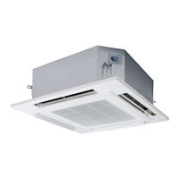
Table of Contents
Table of Contents
2
Safety Precautions
2
Precautions for Use
5
Names of Parts
6
Maintenance
7
Operation Mechanism
7
Troubleshooting
8
Before Requesting Services
9
Specifications
11
Indoor Unit
11
Outdoor Unit
12
Corresponding Language Table
15
Advertisement
Related Products
Panasonic S-71PU1R5
PANASONIC S-71PU1E5
Panasonic S-71PU1E5A
Panasonic S-71PU1R5A
Panasonic S-71PU2E5A
PANASONIC S-71PT1E5
Panasonic S-71PT2E5A
Panasonic S-71PK1E5A
Panasonic S-71PT2E5
Panasonic S-71PT2E5B
PANASONIC Categories
Camcorder
Air Conditioner
TV
Digital Camera
Cordless Telephone
More PANASONIC Manuals
Login
Sign In
OR
Sign in with Facebook
Sign in with Google
Upload manual
Upload from disk
Upload from URL