Sign In
Upload
Manuals
Brands
Panasonic Manuals
Telephone
VB-43030
Panasonic VB-43030 Manuals
Manuals and User Guides for Panasonic VB-43030. We have
2
Panasonic VB-43030 manuals available for free PDF download: Installation Manual
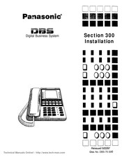
Panasonic VB-43030 Installation Manual (204 pages)
Digital Business System Section 300 (Applies to CPC-AII/B Version 9.2 and CPC-EX Version 2.3)
Brand:
Panasonic
| Category:
Telephone
| Size: 3.1 MB
Table of Contents
Table of Contents
3
About this Manual
11
Purpose
11
Related Information
11
Chapter 1 Requirements
13
Model Numbers
13
FCC Requirements
13
General Requirements
13
Table 1-1. DBS Model Numbers
13
Table 1-2. FCC Information
14
Table 1-3. Interface Information
14
DID Requirements
15
T1 Requirements
16
Environmental Requirements
16
Cleaning
17
Chapter 2 System Overview
19
Cabinet Description
21
Figure 2-1. the DBS Cabinet (DBS 96 Shown)
21
Configurations
23
Table 2-1. Trunk and Extension Capacities According to System Size
23
Printed Circuit Cards
24
Table 2-2. Printed Circuit Card Descriptions and Maximums
24
Table 2-3. Printed Circuit Package Slot Usage
26
Processor Description
27
Table 2-4. CPC/SCC Features
27
Chapter 3 Cabinet Installation
29
Wall-Mounting the Cabinet
31
Guidelines
31
Installation
31
Figure 3-1. Cover Removal
31
Figure 3-2. Cabinet Mounting Bracket
32
Figure 3-3. Cabinet Wall-Mounting
32
Grounding
33
Guidelines
33
Installation
33
Figure 3-4. Cabinet Ground Screw
33
Card Installation
34
Guidelines
34
Figure 3-5. SCC-B Switch 4
34
Figure 3-6. CPC Strap S1
35
Installation
36
Figure 3-7. Printed Circuit Card Installation
36
Battery Backup
37
Guidelines
37
Table 3-1. Battery Backup Packages for the DBS 40, 72, and 96
37
Installation for the DBS 40
38
Figure 3-8. Battery Location, DBS 40
38
Installation for the DBS 72 and 96
39
Figure 3-9. Battery Tray, DBS 72 and 96
39
Figure 3-10. Battery Pack Connection, DBS 72 and 96
40
Key Phone Wall Mounting
41
Figure 3-11. Wall-Mount Adaptor Removal
41
Figure 3-12. Wall-Mount Adaptor Replacement
42
Figure 3-13. Handset Guide Insertion for Wall-Mounting, Key Phone
42
DSLT Wall Mounting
43
Figure 3-14. Desk Stand Removal for DSLT Wall Mounting
43
Figure 3-15. Desk Stand Attachment for DSLT Wall Mounting
44
Figure 3-16. Handset Guide Insertion for Wall-Mounting, DSLT
44
System Initialization
45
Figure 3-17. CPC Memory Clear Switch
45
Test Phone
46
Guidelines
46
Installation
46
Figure 3-18. Test Telephone Connection
47
Chapter 4 Trunks and Lines
49
Trunks
51
Trunk Connectors
51
Figure 4-1. DBS Trunk Connections (DBS 96)
51
Trunk Connector Pinouts
52
Table 4-1. Main Trunks and Expansion Trunks Provided with each System Type
52
Table 4-2. Pinouts and Trunk Numbers for the Main Trunk Connector
53
Table 4-3. Pinouts and Trunk Numbers for Trunk Expansion Connector CN1
54
Loop-Start Trunks
55
Figure 4-2. L-TRK Card Strap J1 and Switch Locations
55
Figure 4-3. Attaching Caller ID Card to the L-TRK Card
56
Ground Start and DID Trunks
57
Table 4-4. -48V Current Consumption for Ground-Start and DID Trunks
57
Table 4-5. -48V Power Supplies Tested with the DBS
57
Figure 4-4. -48Vpower Supply Installation
58
T1 Interface
59
Table 4-6. T1 Hardware Requirements for Single-Cabinet Systems
59
Table 4-7. T1 Hardware Requirements for Double-Cabinet Systems
60
Table 4-8. T1 Slot Usage for Two-Cabinet Systems
61
Table 4-10. T1 and Analog Trunk Assignments, DBS 72
62
Table 4-9. T1 and Analog Trunk Assignments, DBS 40
62
Table 4-11. T1 and Analog Trunk Assignments, DBS 96
63
Table 4-12. Maximum T1 Assignments for Two-Cabinet Systems
63
Table 4-13. T1 and Analog Trunk Assignments, DBS 40 + 40 (16-Channel Fractional T1 in the Slave)
64
Table 4-14. T1 and Analog Trunk Assignments, DBS 72 + DBS 72 (24-Channel T1 in the Slave)
64
Table 4-15. T1 and Analog Trunk Assignments, DBS 96 + DBS 40 (24-Channel T1 in the Master; 16-Channel T1 in the Slave)
65
Table 4-16. T1 and Analog Trunk Assignments, DBS 96 + DBS 72 (24-Channel T1 in the Master; 24-Channel T1 in the Slave)
66
Table 4-17. T1 and Analog Trunk Assignments, DBS 96 + DBS 96 (24-Channel T1 in the Master 24-Channel T1 in the Slave)
67
Figure 4-5. Connector 4 (CN4) Strapping, Sync Unit
69
Figure 4-6. T1 Sync Unit Installation
70
Figure 4-7. T1 MDF Card Installation
71
Figure 4-8. Sync Unit and T1 Connection, Single-Cabinet Installation
72
Figure 4-9. RJ48 Pinouts, CN1 Connector
73
Figure 4-10. T1 Cabinet Connections, Single-Cabinet Installation
74
Figure 4-11. Sync Cable Connections, Double-Cabinet with a T1 in the Slave
76
Figure 4-12. Clock Sync Cable and Sync Cable Connections, Double-Cabinet Installation
78
Lines
79
Extension Connectors
79
Figure 4-13. DBS Extension Connections
79
Extension Connector Pinouts
80
Analog Extensions
85
Figure 4-14. SLT Ringer Box Installation
86
Figure 4-15. EMI Filter Installation (DBS 40 Only)
88
Digital Extensions
89
Figure 4-16. DSS/72 Connection Using One Cable with Two Pairs
90
Figure 4-17. EM/24 Connection Using One Cable with Two Pairs
91
Trunk and Line Expansion
92
Figure 4-18. Trunk or Extension Expansion
93
Chapter 5 Peripheral Equipment
95
Local Terminal or SMDR Device
97
Guidelines
97
Table 5-1. RS-232C Pin Designations Used for CN6
97
Installation
98
Figure 5-1. RS-232C Connection
98
Figure 5-2. SMDR Format for CPC-AII and CPC-B Version 3.1 or Higher
99
Remote Administration Interface (RAI)
100
Guidelines
100
Installation
100
Table 5-2. RAI Compatibility
100
Figure 5-3. RAI Connection
101
Background Music/Music-On-Hold
102
Guidelines
102
Installation
102
Figure 5-4. Installation of Music-On-Hold and Background Music
103
Off-Premises Adaptor (OPX)
104
Guidelines
104
Installation
105
Figure 5-5. Cable Punch-Out Plate, OPX Adaptor
105
Figure 5-6. OPX Installation
107
Paging
108
Guidelines
108
External Page Zone Installation
108
Figure 5-7. External Zone Paging Installation
109
External General Page/Una Installation
110
Figure 5-8. External General Page/Una Installation
110
External Ringer (una Device)
111
Guidelines
111
Installation
112
Figure 5-9. External Ringer (una Device) Installation
112
Power Failure Unit
113
Guidelines
113
Installation
113
Figure 5-10. Cable Punch-Out Plate, Power Failure Unit
114
Figure 5-11. Power Failure Unit (PFU) Installation
115
Voice Announce Unit (VAU)
116
Guidelines
116
Installation
116
Table 5-6. Switch Settings for DTMF Detection Timing, VAU
117
Table 5-7. Switch Settings for Wait Timing between Dialed Digits, VAU
117
Figure 5-12. Cable Punch-Out Plate, Voice Announce Unit
118
Figure 5-13. Extension Cord Connection to the VAU
119
Figure 5-14. Voice Announce Unit (VAU) Installation
119
Recording and Playing Messages
120
Door Box Adaptor (Trunk Port)
121
Guidelines
121
Installation
122
Figure 5-15. Cable Punch-Out Plate, Door Box Adaptor
123
Figure 5-16. Installation of the Door Box, Door Opener, and Door Sensor
124
Door Box Adaptor (Extension Port)
125
Figure 5-17. Cable Punch-Out Plate, Door Box Adaptor
125
Figure 5-18. Installation of the Door Box, Door Opener
126
Figure 5-19. Connections to the Door Box Adaptor
127
Single Line Telephone Adaptor
128
Figure 5-20. Cable Punch-Out Plate, SLTA
128
Figure 5-21. SLTA Installation
130
Chapter 6 Double-Cabinet Systems
131
Guidelines
133
Table 6-1. Trunk and Extension Port Maximums for Double-Cabinet Systems
133
Figure 6-1. Slot Usage for Two-Cabinet Systems, DBS 40 + DBS 40
134
Figure 6-2. Slot Usage for Two-Cabinet Systems, DBS 72 + DBS 40
135
Figure 6-3. Slot Usage for Two-Cabinet Systems, DBS 72 + DBS 72
136
Figure 6-4. Slot Usage for Two-Cabinet Systems, DBS 96 + DBS 40
137
Figure 6-5. Slot Usage for Two-Cabinet Systems, DBS 96 + DBS 72
138
Figure 6-6. Slot Usage for Two-Cabinet Systems, DBS 96 to DBS 96
139
Installation
140
Figure 6-7. Strap 3, MFR Card
140
Figure 6-8. Double-Cabinet Installation
141
Figure 6-9. CBL-S to Connector Panel Connection, Slave Cabinet
141
Chapter 7 Specifications
143
Electrical Characteristics
145
Table 7-1. Input Power
145
Table 7-2. Power Consumption and Heat Generation
145
Table 7-3. Battery Backup Capacity
145
Environmental Requirements
146
Table 7-4. Temperature and Humidity Requirements
146
Table 7-5. Dimensions and Weight, Single-Cabinet Systems and Phones
146
Table 7-6. Dimensions for Two-Cabinet Systems
146
Resource Maximums
147
Table 7-7. Trunk and Line Capacities
147
Table 7-8. Feature-Related Capacities
147
Table 7-9. Hardware Maximums for Single-Cabinet Systems
149
Table 7-10. Hardware Maximums for Double-Cabinet Systems
152
Cabling Specifications
155
Table 7-11. Maximum Cabling Distances
155
Communication Parameters
156
Table 7-12. Voice Path from Ktels to DBS
156
Table 7-13. Data Communications Ports
156
Signaling Characteristics
157
Table 7-14. Signaling to CO
157
Table 7-15. Signaling Levels
157
Table 7-16. Transmission Specifications
157
Tone Characteristics
158
Table 7-17. Tone Plan
158
Table 7-18. DTMF Frequencies
159
Appendix A: CPC-EX 1.0 Updates
161
Compatibility
161
44-Series Phone Support
161
Directory Mode
162
Variable Mode
162
Handset Mute
162
Off-Hook Monitoring
162
Analog Adapter
162
MSG (Message) Key
162
DSS/72 and EM/24 - Key Arrangement
162
FF-Key Programming
163
Speed Dial Enhancements
163
Additional Serial Port
163
T1 Networking Capability
163
Modification to Toll Restriction Service
163
Maximum Time Priority Route Tables
163
SMDR Modifications
164
ISDN Support
164
Modification to T1 Signaling Types
164
Installation Notes
164
CPC-EX Installation
164
44-Series Enhanced Phone Features
167
Analog Adapter
172
MSG (Message) Key
173
DSS/72 Console - Key Arrangement
175
Contents
182
Analog Adapter
188
DSS/72 Console - Key Arrangement
190
Page B
192
EM/24 - Key Arrangement
193
Appendix B: CPC-AII/B 8.0 Updates
194
TAPI Support
194
Key Telephone Installation Notes
194
Desi Strip Cover
194
Key Telephone Wall Mounting Instructions
194
Index
197
Advertisement
Panasonic VB-43030 Installation Manual (159 pages)
Digital Business System
Brand:
Panasonic
| Category:
Desktop
| Size: 2.49 MB
Table of Contents
Table of Contents
3
Purpose
11
Related Documents
11
Chapter 1. Requirements
12
Model Numbers
14
FCC Requirements
14
General Requirements
14
DID Requirements
16
Tl Requirements
16
Environmental Requirements
16
Chapter 2. System Overview
18
Cabinet Description
20
Configurations
22
Printed Circuit Cards
23
Processor Description
26
Chapter 3. Cabinet Installation
29
Wall-Mounting the Cabinet
29
Guidelines
29
Installation
29
Guidelines
31
Installation
31
Card Installation
32
Guidelines
32
Installation
34
Battery Backup
35
Guidelines
35
Installation for the DBS 40
36
Installation for the DBS 72 and 96
37
Key Phone Wall Mounting
39
DSLT Wall Mounting
41
System Initialization
43
Test Phone
44
Guidelines
44
Installation
44
Chapter 4. Trunks and Lines
46
Trunks
48
Trunk Connectors
48
Tmnk Connector Pinouts
49
Loop-Start Trunks
52
Ground Start and DID Trunks
54
Tl Interface
56
Lines
76
Extension Connectors
76
Extension Connector Pinouts
77
Analog Extensions
82
Digital Extensions
85
Trunk and Line Expansion
88
Chapter 5. Peripheral Equipment
90
Local Terminal or SMDR Device
92
Guidelines
92
Installation
93
Remote Administration Interface (RAI)
95
Guidelines
95
Installation
95
Background Music/Music-On-Hold
97
Guidelines
97
Installation
97
Off-Premises Adaptor (OPX)
99
Guidelines
99
Installation
100
Paging
103
Guidelines
103
External Page Zone Installation
103
External General Page/Una Installation
105
External Ringer (una Device)
106
Guidelines
106
Installation
107
Power Failure Unit
108
Guidelines
108
Installation
108
Voice Announce Unit (VAU)
111
Guidelines
111
Installation
111
Recording and Playing Messages
115
Door Box Adaptor (Trunk Port)
116
Guidelines
116
DBS Manual - Issued 8/T/95
116
Installation
117
Door Box Adaptor (Extension Port)
120
Single Line Telephone Adaptor
123
Guidelines
128
Installation
135
Chapter 7. Specifications
140
Electrical Characteristics
140
Table 7-3. Battery Backup Capacity
140
Environmental Requirements
141
Table 7-4. Temperature and Humidity Requirements
141
Table 7-6. Dimensions for Two-Cabinet Systems
141
Resource Maximums
142
Table 7-8. Feature-Related Capacities
142
Table 7-9. Hardware Maximums for Single-Cabinet Systems
144
Cabling Specifications
150
Table 7- 11. Maximum Cabling Distances
150
Communication Parameters
151
Table 7-13. Data Communications Ports
151
Signaling Characteristics
152
Table 7-14. Signaling to CO
152
Tone Characteristics
153
Table 7-17. Tone Plan
153
Table 7- 18. DTMF Frequencies
154
Advertisement
Related Products
Panasonic VoiceSonic VB-43221
Panasonic VoiceSonic VB-43223
Panasonic VoiceSonic VB-43225
Panasonic VoiceSonic VB-43233
Panasonic VoiceSonic VB-43220
Panasonic VB-43230' VB-43233
Panasonic VB-43050
Panasonic VB-43060
Panasonic VB44020 - DBS 576 PORT SYS OP
Panasonic VB44223 - BUSINESS TELEPHONE
Panasonic Categories
Camcorder
Air Conditioner
TV
Digital Camera
Cordless Telephone
More Panasonic Manuals
Login
Sign In
OR
Sign in with Facebook
Sign in with Google
Upload manual
Upload from disk
Upload from URL