Sign In
Upload
Manuals
Brands
Sanyo Manuals
Air Conditioner
48 series
Sanyo 48 series Manuals
Manuals and User Guides for Sanyo 48 series. We have
2
Sanyo 48 series manuals available for free PDF download: Technical Data & Service Manual, Installation Instructions Manual
Sanyo 48 series Technical Data & Service Manual (275 pages)
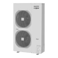
Big Pack I DC inverter
Brand:
Sanyo
| Category:
Air Conditioner
| Size: 18.46 MB
Table of Contents
-- Contents --
5
Service Manual
1
Technical Data
1
Combination of Indoor and Outdoor Units
4
Table of Contents
5
Specifications
6
Unit Specifications
7
4-Way Air Discharge Semi-Concealed Type
7
Wall-Mounted Type
18
Ceiling-Mounted Type
21
Concealed-Duct Type
31
1-2. Major Component Specifications
54
Major Component Specifications
54
(A) Indoor Units
54
(B) Outdoor Units
72
Other Component Specifications
74
4-Way Air Discharge Semi-Concealed Type
74
Wall-Mounted Type
76
Ceiling-Mounted Type
77
Concealed-Duct Type
78
Dimensional Data
82
Refrigerant Flow Diagram
97
Operating Range
97
Capacity Correction Graph According to Temperature Condition
98
Noise Criterion Curves
99
(A) Indoor Units
99
4-Way Air Discharge Semi-Concealed Type
99
Wall-Mounted Type
101
Ceiling-Mounted Type
102
Concealed-Duct Type
103
(B) Outdoor Units
106
Indoor Fan Performance
107
1-9. Indoor Fan Performance
109
1-8. Noise Criterion Curves
109
Airflow Distance Chart
109
Intaking Fresh Air of Semi-Concealed Type and Concealed-Duct Type
118
Installation Instructions
120
Tubing Length
120
Optional Distribution Joint Kits
124
Installing Distribution Joint Kit (for Triple)
126
Selecting the Installation Site
127
Dimensions of Snow-Proof Duct
137
How to Install the Outdoor Unit
140
Electrical Wiring
141
2. Test Run
146
Test Run
146
Preparing for Test Run
147
X, XM, T, U, US, D Types
147
Caution
147
Test Run Procedure
147
Items to Check before the Test Run
148
Precautions
148
Test Run Using the Remote Controller
148
Caution
154
System Control
154
K Type
154
Items to Check before the Test Run
155
Preparation for Test Run
155
Test Run Procedure
155
Precautions
156
Test Run
156
Table of Self-Diagnostic Functions and Corrections (K Type)
157
System Control
158
X, T, U, D Types (for Link Wiring) Caution
161
Items to Check before the Test Run
162
Test Run Procedure
162
Test Run Using the Remote Controller
162
Table of Self-Diagnostic Functions and Corrections (X, T, U, D Types)
163
Automatic Address Setting
164
K Type
166
K Type (for Link Wiring)
166
Caution
166
Test Run Procedure
167
Table of Self-Diagnostic Functions and Corrections (K Type)
168
Automatic Address Setting
169
XM Type (for Link Wiring)
172
Caution
172
Test Run Procedure
172
Items to Check before the Test Run
173
Test Run Using the Remote Controller
173
Table of Self-Diagnostic Functions and Corrections (XM Type)
174
Automatic Address Setting
175
Caution for Pump down
177
3. Electrical Data
180
Electrical Data
180
Indoor Units (Electric Wiring Diagram, Schematic Diagram)
181
4-Way Air Discharge Semi-Concealed Type
181
Ceiling-Mounted Type
188
Concealed-Duct Type
190
Concealed-Duct High-Static Pressure Type
198
Outdoor Units (Electric Wiring Diagram, Schematic Diagram)
202
Process and Functions
204
Control Functions
205
Outdoor Unit Control PCB
211
Indoor Unit Control PCB Switches and Functions
214
5. Service Procedures
218
Service Procedures
218
Meaning of Alarm Messages
219
Contents of LED Display on the Outdoor Unit Control PCB
221
Symptoms and Parts to Inspect
222
Details of Alarm Messages
225
Table of Thermistor Characteristics
231
How to Remove the Compressor
232
How to Remove the Electrical Component Box
233
6. Outdoor Unit Maintenance Remote Control
234
Outdoor Unit Maintenance Remote Control
234
Overview
235
Functions
235
Normal Display Operations and Functions
236
Monitoring Operations: Display of Indoor Unit and Outdoor Unit Sensor Temperatures
239
Monitoring the Outdoor Unit Alarm History: Display of Outdoor Unit Alarm History
240
Settings Modes: Setting the Outdoor Unit EEPROM
240
7. Remote Controller Functions Section
244
Remote Controller Functions Section
244
Simple Settings Function
245
List of Simple Setting Items
246
Detailed Settings Function
247
List of Detailed Setting Items
248
Simple Setting Items
252
Detailed Setting Items
255
Detaild Setting Items
255
Remote Controller Servicing Functions
259
Test Run Function
259
8. How to Install the Wireless Remote Controller Receiver
262
How to Install the Wireless Remote Controller Receiver
262
Warning
262
RCS-SH80BG.WL for 4-Way Cassette (X Type)
262
RCS-TRP80BG.WL for Ceiling Mounted (T Type)
262
RCS-BH80BG.WL for XM, U and US Types
262
Common to All Models
262
Warning about Installation of Receivers
263
Warning about Installing Remote Controls
263
Installing the Receiver Unit
264
Accessories
265
Wiring the Receiver Unit
265
Precautions on Simultaneous Installation of Wired Remote Controller and Wireless Remote Controller
265
Test Operation
266
Setting Address Switches
266
Installing the Receiver Unit
267
Accessories
268
Wiring the Receiver Unit
268
Precautions on Simultaneous Installation of Wired Remote Controller and Wireless Remote Controller
268
Test Operation
269
Setting Address Switches
269
Accessories
270
Installing the Receiver Unit
270
Wiring the Receiver Unit
271
Setting Address Switches
272
Test Operation
272
8-21. Room Temperature Sensor Settings
274
8-20. the Self-Diagnosis Function Display and What Is Detected
274
Setting up Remote Control Functions
274
Advertisement
Sanyo 48 series Installation Instructions Manual (110 pages)
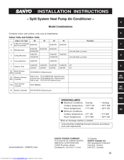
Split System Heat Pump Air Conditioner
Brand:
Sanyo
| Category:
Air Conditioner
| Size: 9.12 MB
Table of Contents
Installation Instructions
1
Important
2
Check of Density Limit
3
Precautions for Installation Using New Refrigerant
4
Table of Contents
6
1 General
8
Tools Required for Installation (Not Supplied)
8
Accessories Supplied with Outdoor Unit
8
Type of Copper Tube and Insulation Material
8
Additional Materials Required for Installation
8
Tubing Size
14
2 Selecting the Installation Site
16
Indoor Unit
16
Outdoor Unit
17
Air-Discharge Chamber for Top Discharge
18
Installing the Unit in Heavy Snow Areas
18
Precautions for Installation in Heavy Snow Areas
18
Dimensions of Wind Ducting
19
Dimensions of Snow Ducting
22
3 How to Install the Indoor Unit
26
1 I 4-Way Air Discharge Semi-Concealed Type
26
(X Type)
26
Suspending the Indoor Unit
26
Preparation for Suspending
26
Placing the Unit Inside the Ceiling
27
Installing the Drain Piping
28
Checking the Drainage
29
Before Installing the Ceiling Panel
30
Installing the Ceiling Panel
31
When Removing the Ceiling Panel for Servicing
31
Duct for Fresh Air
32
I Wall-Mounted Type (K Type)
34
Removing the Wall Fixture from the Unit
34
Selecting and Making a Hole
34
Installing the Rear Panel on the Wall
37
Removing the Grille to Install the Indoor Unit
39
Preparing the Indoor Side Tubing
41
Wiring Instructions
42
Wiring Instructions for Inter-Unit Connections
43
Shaping the Tubing
46
Installing the Drain Hose
46
I Ceiling-Mounted Type (T Type)
47
Suspending the Indoor Unit
47
Duct for Fresh Air
50
Installing the Drain Piping
50
I Concealed-Duct Type (U Type)
51
Required Minimum Space for Installation and Service
51
Suspending the Indoor Unit
52
Installing the Drain Piping
53
Checking the Drainage
54
Increasing the Fan Speed
55
How to Install the Outdoor Unit
56
Installing the Outdoor Unit
56
Drainage Work
56
Routing the Tubing and Wiring
56
5 Electrical Wiring
57
General Precautions on Wiring
57
Recommended Wire Length and Wire Diameter for Power Supply System
57
Wiring System Diagrams
58
How to Connect Wiring to the Terminal
59
6 How to Install the Wired Remote Controller (Optional Part)
60
Installation Site Selection
60
Wired Remote Controller Installation
61
Basic Wiring Diagram
62
Wiring System Diagram for Group Control
63
Wiring System Diagram for Multiple Remote Controllers
64
How to Switch the Indoor Temperature Sensor
64
Trouble Diagnostics
65
7 How to Install the Wireless Remote Controller (Optional Part)
68
Wireless Remote Controller Installation
68
Room Temperature Sensor Setting
69
Address Switches
69
Setting the Model Code
69
Rcs-Sh80Ua.wl
70
4-Way Air Discharge Semi-Concealed Type
70
(X Type)
70
Indicator Section Installation
70
Operating Controller Installation
70
I Ceiling-Mounted Type (T Type)
71
Indicator Section Installation
71
Operating Controller Installation
71
Electrical Wiring
72
Test Run Switch
72
Misoperation Alarm Indicators
73
Operation Controller
73
Rcs-Bh80Ua.wl
74
Separate Type Signal Receiving Unit Installation
74
Machine Screws
75
Electrical Wiring
76
Test Run Switch
76
Misoperation Alarm Indicators
77
Basic Wiring Diagram
80
Wiring System Diagram for Multiple Remote Controllers
80
Rcs-Sh1Ua
81
Test Run Procedure
81
Check Items before the Test Run
81
Preparing for the Test Run
82
Precautions
83
8 How to Install the System Controller (Optional Part)
84
System Controller Installation
84
Electrical Wiring
85
Address Switch Setting
86
Mode Setting
88
How to Perform Zone Registration
89
Connection with Other Equipment
95
Memory Backup Switch
95
Test Run
95
9 How to Process Tubing
96
Connecting the Refrigerant Tubing
96
Connecting Tubing between Indoor and Outdoor Units
97
Insulating the Refrigerant Tubing
98
Vinyl Clamps
98
Taping the Tubes
99
Finishing the Installation
99
10 Leak Test, Evacuation and Additional
100
Refrigerant Charge
100
Leak Test
100
Evacuation
101
Charging Additional Refrigerant
102
Finishing the Job
102
11 Test Run
103
Preparing for Test Run
103
Spacers
103
Caution
104
Test Run Procedure
104
Items to Check before the Test Run
105
Test Run Using the Remote Controller
105
Precautions
105
Examples of Wiring Diagrams
107
Advertisement
Related Products
Sanyo 42TW72R
Sanyo 42XHW72R
Sanyo 42THW72R
Sanyo 400 BTU Ductless Multi-Split Low Ambient Air Conditioner
Sanyo 48RS22N
Sanyo 42LM4WPTC
Sanyo 42LM5WPTC
Sanyo 432-318-51
Sanyo 437 482 03
Sanyo 43743240
Sanyo Categories
Projector
TV
Air Conditioner
Security Camera
LCD TV
More Sanyo Manuals
Login
Sign In
OR
Sign in with Facebook
Sign in with Google
Upload manual
Upload from disk
Upload from URL