Sign In
Upload
Manuals
Brands
Siemens Manuals
Switch
15-FSV-750
Siemens 15-FSV-750 Manuals
Manuals and User Guides for Siemens 15-FSV-750. We have
1
Siemens 15-FSV-750 manual available for free PDF download: Installation Operation & Maintenance
Siemens 15-FSV-750 Installation Operation & Maintenance (48 pages)
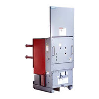
Vacuum Circuit Breakers FSV series and MSV series
Brand:
Siemens
| Category:
Switch
| Size: 1.71 MB
Table of Contents
Table of Contents
3
General
6
Introduction
6
Receiving
6
Figure CI Rcuit Breaker Handling I Nstruct I Ons
7
Storage
8
"As Found" Tests
8
Installation Checkout
8
Figure 9. Vac Uum Breaker Mechanism - Cl Osed P Osit I on and Tripping Springs Charged
9
Circuit Breaker Elevations
10
Figure 10. Operating Mechanism - Details of Cl Osing Spring Charging Com P Onents
10
Figure 2 . A. MSV Breaker Front and Side E Levation View
11
Figure 11 . Operating Mechanism - Open P Osition Tri Pping Spring Charged and Latched
11
Technical Data
13
Rating Plate Content
13
Rating Summary
14
Figure 3 Rating Plate
14
Service Conditions
15
General Performance Data
15
Interrupter/Operator-Description
16
Interrupter/Operator Su Bassembly
16
Construction
16
Breaker Pole
17
Current-Path Assembly
17
Vacuum Interrupter
17
The Arc Quenching Principle
17
Figure 6 Section through a Vacuum Breaker Pole
18
Figure 7 Section T Hrough a Vacuum Interrupter
18
Figure 8 . Secti on through the Vacu um Breaker
18
Switching Operation
19
Operating Mechanism
19
Construction
20
Indi Rect Rel Eases
20
Motor Operating Mechanism
20
Auxiliary Switches
20
Mode of Operation
20
Charging
20
Closin G
21
Trip Free Operation
21
Opening
22
Rapid Auto-Reclosing
22
Manual Operation
22
Manually Charging the Closing S P Ring
22
Figure 12 . View of Mechanism - Breaker Shaft I N Open Positi on
22
Figure 13. Front View of Mechanism Enclos U Re Arranged F or Manual Operation
22
Figure 1 4 Operator Sequential Operation Diagram
23
Manual Closing
24
Manual Opening
24
Elementary Diagram
24
Indi Rect Releases (Dual Tri P & Undervoltage)
24
Figure 15. Typical Elementary Diagram
24
Secondary Release
25
Undervoltage Release
25
Construction and Mode of Operation
25
Figure 16 . Construction of Shunt Release
25
Figure 16.A. Latch Detail S H Unt Release - S H Own Charged
25
Figure Undervoltage Bl Ocking Feature
26
Figure 17. Capacitor Trip Device
26
Capacitor Trip Device
27
Interrupter/Operator-Maintenance
28
General
28
Inspection Check List
28
Hand Tools Recommended
28
Metric
28
English
28
Minimum Maintenance Schedule
29
Lubrication
29
Overhaul
29
Lubrication of the Operating Mechanism
29
Vacuum Interrupters
30
Contact Erosion
30
Figure 18 Lubrication of Operator
30
Interrupter Vacuum Check-Mechanical
31
High Potential Testing and Electrical Interrupter Vacuum Check
31
Figure 19. Typical Primary I Nterrupter Contact Life Curves
31
Figure 20 Contact Erosion Check
31
Vacuum Tube Replacement
32
Figure 21A Lower Pole Support with Insulated Coupler
32
Figure Primary Contact Cl Osed - Free P Osit I on
33
Figure Primary Contact Forced Open by Manual Press Ure
33
Figure 22 . Vac Uum Tube Replacement I L L Ustrat I on
34
Figure 23 Illustration Showing Required Technique for Fastening Terminal Clamp Hardware
35
Hydraulic Shock Absorber
36
Vehicle-Description
37
Vehicle Function and Operational Interlocks
37
Alignment
37
Breaker Racking Interlock (Lever Type)
37
Breaker Racking Interlock (Screw Type)
38
Figure 24.A-1. Details of the Breaker Racking I Nter L Ock - Type FSV
38
Figure Details of the Breaker Racking I Nter L Ock - Type MSV
38
Plunger Position Mechanical Interlock
39
Automatic Closing Spring Release
39
Figure Details of the Breaker Racking I Nterl Ock - I Nternal T O Mechanism Enc L os U Re
40
Figure 25. A. Details of the a Ut Omatic Cl Osing Spring Dischrge System - Type MSV
41
Figure Details of the Automatic Cl Osing S P Ring Discharge System - Type FSV
42
Figure 26 . 1200, 2000 and 3000 Amp Contin Uous Cu Rrent I Nter L Ock O Rientat I on
42
Continuous Current Interlock
43
Control Cable and Connection Box
43
Figure 27 . Control Ca Ble Connecti on Detail
43
Insulating Barrier-Type FSV
44
Front Hinged Panel, Type FSV
44
Figure 28 Insulating Barrier-Type FSV
44
Figure 29. FSV Hinged F R Ont Panel
44
Cubicle Interface Barrier for Type MSV & FSV Circuit Breakers
45
Vehicle-Maintenance
46
Vehicle Lubrication
46
Warranty
47
Advertisement
Advertisement
Related Products
Siemens 15-FSV-1000
Siemens 15-FSV-500
Siemens Type 1
Siemens Type 12
Siemens HiPath 1100 V7.0
Siemens Hicom 150 E/150 H
Siemens OpenStage 15 T
Siemens Gigaset 150
Siemens OpenStage 15 G
Siemens ADB MEMOPACK 15 XT
Siemens Categories
Industrial Equipment
Controller
Control Unit
Oven
Washer
More Siemens Manuals
Login
Sign In
OR
Sign in with Facebook
Sign in with Google
Upload manual
Upload from disk
Upload from URL