Sign In
Upload
Manuals
Brands
Siemens Manuals
Media Converter
6SL3517-1BE11-3AM0
Siemens 6SL3517-1BE11-3AM0 Manuals
Manuals and User Guides for Siemens 6SL3517-1BE11-3AM0. We have
1
Siemens 6SL3517-1BE11-3AM0 manual available for free PDF download: Operating Instructions Manual
Siemens 6SL3517-1BE11-3AM0 Operating Instructions Manual (428 pages)
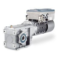
Distributed converter for SIMOGEAR geared motors
Brand:
Siemens
| Category:
Media Converter
| Size: 27.89 MB
Table of Contents
Changes in this Manual
5
Table of Contents
7
1 Fundamental Safety Instructions
13
General Safety Instructions
13
Equipment Damage Due to Electric Fields or Electrostatic Discharge
19
Warranty and Liability for Application Examples
20
Security Information
21
Residual Risks of Power Drive Systems
22
2 Introduction
23
About the Manual
23
3 Description
25
Identifying the Components of the System
26
SINAMICS G110M Converter
27
General Layout SINAMICS G110M System
31
Directives and Standards
36
4 Installation
39
Mechanical Installation
40
System Installation
44
Overview
44
Disassembly
46
Installation
48
Grounding the Terminal Housing
57
Installing the 24V Power Supply
57
Electrical Installation
62
SINAMICS G110M Electrical Data
62
EMC Installation Guidelines
64
Connections and Interference Suppression
64
Basic EMC Rules
64
Equipotential Bonding
65
Protective Conductor
67
Connection and Cables
69
Connecting the Motor to the Converter in a Star or Delta Connection
76
Cable Protection
78
Operation with Residual Current Protective Device (RCD)
80
Connecting the PROFINET Interface
81
Terminal Assignment Dependent on Interface Configuration
81
Wiring Example for the Factory Settings
82
Connecting the Converter to the Fieldbus
90
Fieldbus Version of the Control Module
90
Profinet
90
Connect the Converter to PROFINET
92
What Do You Have to Set for Communication Via PROFINET
92
Installing GSDML
93
Profibus
93
Integrating the Converter in PROFIBUS
93
What Do You Have to Set for Communication Via PROFIBUS
94
Installing the GSD
94
Set the PROFIBUS Address
95
Communications Via AS-I
96
Setting the Address
97
Using the AS-I Programmer
99
5 Commissioning
101
Commissioning Guidelines
101
Commissioning Tools
102
Prepare Commissioning
103
Collecting Motor Data
103
Converter Factory Setting
104
V/F Control or Speed Control
106
Minimum and Maximum Speed
107
Quick Commissioning
108
Motor Data Using P300 and P301
108
Quick Commissioning with DIP Switches
110
Commissioning with the IOP-2
115
P0015 Default Settings
118
Quick Commissioning with a PC
124
Creating a Project
125
Transfer Converters Connected Via USB into the Project
126
Go Online and Start the Commissioning Wizard
127
Selecting the Control Mode
129
Identify Motor Data
130
Restoring the Factory Settings
132
Saving Motor Data for Non-Standard Motors
132
Resetting the Safety Functions to the Factory Setting
134
Restore the Settings to the Factory Settings (Without Safety Functions)
135
Series Commissioning
137
6 Uploading the Converter Settings
139
Why Does an Upload Make Sense
139
Uploading to the Memory Card
140
Recommended Memory Cards
140
Automatic Upload
141
Message for a Memory Card that Is Not Inserted
142
Manual Upload with Startdrive
142
Safely Remove the Memory Card with Startdrive
144
Upload to a PC Using Startdrive
145
More Options for the Upload
146
7 Protecting the Converter Settings
147
Write Protection
147
Know-How Protection
149
Extending the Exception List for Know-How Protection
153
Activating and Deactivating Know-How Protection
154
8 Advanced Commissioning
157
Overview of Converter Functions
157
Brief Description of the Parameters
160
Sequence Control When Switching the Motor on and off
161
Adapt the Default Setting of the Inputs and Outputs
164
Digital Inputs
164
Analog Inputs as Digital Inputs
165
Digital Outputs
166
Analog Inputs
168
Adjusting Characteristics for Analog Input
170
Setting the Deadband
171
Controlling Clockwise and Counter-Clockwise Rotation Via Digital Inputs
172
Two-Wire Control, On/Reverse
174
Two-Wire Control, Clockwise/Counterclockwise Rotation 1
176
Two-Wire Control, Clockwise/Counterclockwise Rotation 2
178
Three-Wire Control, Enable/Clockwise/Counterclockwise Rotation
180
Three-Wire Control, Enable/On/Reverse
182
Drive Control Via PROFIBUS or PROFINET
184
Receive Data and Send Data
184
Telegrams
185
Control and Status Word 1
190
Control and Status Word 3
192
NAMUR Message Word
195
Parameter Channel
196
Examples
204
Expanding or Freely Interconnecting Telegrams
206
Slave-To-Slave Communication
209
Acyclically Reading and Writing Converter Parameters
209
Control Via AS-I
210
Single Slave Mode
210
Dual Slave Mode
211
Assignment Tables
214
Cyclic and Acyclic Communication Via CTT2
216
Cyclic Communication
217
Acyclic Communication - Standard
218
Acyclic Communication - Manufacturer-Specific
218
Jogging
220
Limit Position Control
222
Quick Stop Function
226
Switching over the Drive Control (Command Data Set)
229
Motor Holding Brake
232
Free Function Blocks
237
Overview
237
Further Information
238
Selecting Physical Units
239
Motor Standard
239
Unit System
239
Technological Unit of the Technology Controller
241
Setting the System of Units and Technology Unit
242
Safe Torque off (STO) Safety Function
244
EMERGENCY SWITCHING off and EMERGENCY STOP
246
Commissioning STO
247
Password
247
Configuring a Safety Function
249
Interconnecting the "STO Active" Signal
250
Signal Filter for STO Selection
251
Setting the Signal Filter for STO Selection
253
Forced Checking Procedure
253
Setting Forced Checking Procedure
254
Complete Commissioning
256
Checking the Assignment of the Digital Inputs
257
Acceptance Test
258
Setpoints
260
Overview
260
Analog Input as Setpoint Source
262
Specifying the Setpoint Via the Fieldbus
263
Electromechanical Potentiometer
264
Motorized Potentiometer as Setpoint Source
265
Fixed Speed Setpoint as Setpoint Source
267
Setpoint Calculation
271
Overview
271
Invert Setpoint
272
Inhibit Direction of Rotation
273
Skip Frequency Bands and Minimum Speed
274
Speed Limitation
276
Ramp-Function Generator
277
PID Technology Controller
282
Motor Control
289
V/F Control
289
Characteristics of U/F Control
293
Selecting the U/F Characteristic
295
Optimizing Motor Starting
296
Sensorless Vector Control with Speed Controller
298
Structure of Vector Control Without Encoder (Sensorless)
298
Optimizing the Closed-Loop Speed Controller
299
Advanced Settings
302
Friction Characteristic
303
Moment of Inertia Estimator
305
Pole Position Identification
310
Torque Control
311
Electrically Braking the Motor
313
Electrical Braking
313
DC Braking
313
Dynamic Braking
318
Overcurrent Protection
321
Converter Protection Using Temperature Monitoring
322
Motor Protection with Temperature Sensor
325
Motor Protection by Calculating the Temperature
328
How Do I Achieve a Motor Overload Protection in Accordance with IEC/UL 61800-5-1
329
Motor and Converter Protection by Limiting the Voltage
330
Monitoring the Driven Load
332
No-Load Monitoring
332
Rotation Monitoring
333
Torque Monitoring
334
Efficiency Optimization
339
Calculating the Energy Saving for Fluid Flow Machines
342
Switchover between Different Settings
344
9 Alarms, Faults and System Messages
347
Status LED Overview
347
Operating States Indicated Via Leds
348
System Runtime
351
Identification & Maintenance Data (I&M)
352
Alarms, Alarm Buffer, and Alarm History
353
Faults, Alarm Buffer and Alarm History
356
List of Alarms and Faults
359
10 Corrective Maintenance
365
Replacing the Control Module
367
Downloading the Converter Settings
369
Converter Without Enabled Safety Functions
369
Automatic Download from the Memory Card
369
Manual Download from the Memory Card Using Startdrive
369
Download from IOP-2 Operator Panel
370
Download from the PC Using Startdrive
372
Converter with Enabled Safety Functions
372
Automatic Download from the Memory Card
372
Download from IOP-2 Operator Panel
373
Download from the PC Using Startdrive
375
Download with Active Know-How Protection with Copy Protection
377
Replacing the Power Module
379
Firmware Upgrade and Downgrade
381
Upgrading Firmware
381
Firmware Downgrade
384
Correcting a Failed Firmware Upgrade or Downgrade
387
Reduced Acceptance Test after Component Replacement and Firmware Change
389
11 Technical Data
391
Performance Ratings of the Control Module - CU240M
391
Performance Ratings Power Module - PM240M
392
SINAMICS G110M Specifications
393
Ambient Operating Temperature
395
Current Derating as a Function of the Installation Altitude
396
Pulse Frequency and Current Reduction
397
Protecting Persons from Electromagnetic Fields
398
Appendix
399
New and Extended Functions
399
Firmware Version 4.7 SP13
399
Firmware Version 4.7 SP10
400
Firmware Version 4.7 SP9
402
Firmware Version 4.7 SP6
404
Firmware Version 4.7 SP3
405
Firmware Version 4.7
407
Firmware Version 4.6 SP6
408
Firmware Version 4.6
409
Interconnecting Signals in the Converter
410
Fundamentals
410
Application Example
412
Electromagnetic Compatibility
414
Manuals and Technical Support
417
Manuals for Your Converter
417
Configuring Support
418
Product Support
419
Index
421
Advertisement
Advertisement
Related Products
Siemens 6SL3517-1BE12-3AM0
Siemens 6SL3517-1BE13-3AM0
Siemens 6SL3517-1BE14-3AM0
Siemens 6SL3517-1BE16-3AM0
Siemens 6SL3517-1BE17-7AM0
Siemens 6SL3517-1BE21-0AM0
Siemens 6SL3210-1KE12-3UF2
Siemens 6SL3210-1KE15-8UF2
Siemens 6SL3210-1KE17-5AP1
Siemens 6SL3210-1KE21-7AB1
Siemens Categories
Industrial Equipment
Controller
Control Unit
Oven
Washer
More Siemens Manuals
Login
Sign In
OR
Sign in with Facebook
Sign in with Google
Upload manual
Upload from disk
Upload from URL