Sign In
Upload
Manuals
Brands
siemens Manuals
Measuring Instruments
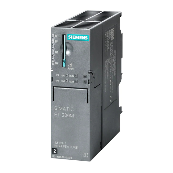
ET 200M
siemens ET 200M Manuals
Manuals and User Guides for siemens ET 200M. We have
1
siemens ET 200M manual available for free PDF download: Manual
siemens ET 200M Manual (284 pages)
Marshalled Termination Assemblies Remote I/O Modules
Brand:
siemens
| Category:
Measuring Instruments
| Size: 4.71 MB
Table of Contents
Table of Contents
9
1 Overview
17
System Architecture
17
Marshalled Termination Assemblies (Mtas)
18
General Construction and Dimensions
20
Interconnecting Cables
22
Interconnecting Cable Assemblies
23
2 Installation
27
Environmental Considerations
29
Et200M Mta
29
Mechanical Installation
30
Electrical Installation
30
Cabinet Guidelines
30
Remote I/O Modules
30
Wiring Guidelines
31
Installation Procedure
32
Without Cover and Frame
32
With Cover and Frame
32
Removal Procedure
33
Without Cover
33
With Cover
33
3 Maintenance
35
Tools and Test Equipment
36
Preventative Maintenance
36
Environmental Consideration
36
Visual Inspection
36
8 Channel Analog Input MTA
37
Description
37
Features
37
Operation
38
Installation Requirements
39
Maintenance
39
8-Channel Analog Input Marshalled Termination Assembly
40
Technical Specifications
42
Module Restrictions
43
Typical Transmitter Connection to Field Terminals
43
Hardware Configuration
45
Addresses
45
Inputs
46
Redundancy
47
Technical Specifications for 8-Channel Analog Input Module (6ES7 331-7NF00-0AB0)
48
8 Channel Analog Input MTA
49
Description
49
Features
49
Modification Vs 8-Channel Analog Input MTA 6ES7650-1AA51-2XX0
49
Operation
50
Installation Requirements
51
Maintenance
51
8-Channel Analog Input Marshalled Termination Assembly
52
Technical Specifications
54
Module Restrictions
57
Typical Transmitter Connection to Field Terminals
57
Hardware Configuration
58
Addresses
58
Inputs
59
Redundancy
60
Technical Specifications for 8-Channel Analog Input Module (6ES7 331-7NF00-0AB0 / 6ES7331-7NF10-0AB0)
60
8 Channel Analog Output MTA
61
Description
61
Features
61
Operation
62
Installation Requirements
62
Maintenance
62
8-Channel Analog Output Marshalled Termination Assembly
63
Technical Specifications
64
Module Restrictions
65
Typical Load Connection to Field Terminals
65
Hardware Configuration
66
Addresses
66
Outputs
67
Redundancy
68
Technical Specifications for 8-Channel Analog Output Module (6ES7 332-5HF00-0AB0)
68
8 Channel RTD Input MTA
69
Description
69
Features
69
Operation
69
Installation Requirements
70
Maintenance
70
8-Channel, RTD Input Marshalled Termination Assembly
71
Technical Specifications
72
Module Restrictions
73
Typical R & RTD Connection to Field Terminals
74
Hardware Configuration
75
Addresses
75
Inputs - Part 1
76
Inputs - Part 2
77
Technical Specifications for 8-Channel RTD Input Module (6ES7 331-7PF00-0AB0 & 6ES7 331-7PF01-0AB0)
77
8 Channel TC Input MTA
79
Description
79
Features
79
Operation
79
Installation Requirements
80
Maintenance
80
8-Channel TC Input Marshalled Termination Assembly
81
Technical Specifications
82
Module Restrictions
83
Typical Thermocouple Connection to Field Terminals
83
Hardware Configuration
84
Addresses
84
Inputs - Part 1
85
Inputs - Part 2
86
Technical Specifications for 8-Channel TC Input Module (6ES7 331-7PF10-0AB0 & 6ES7 331-7PF11-0AB0)
86
6 Channel F Analog Input MTA
87
Description
87
Features
87
Operation
88
Installation Requirements
90
Maintenance
91
6-Channel F Analog Input Marshalled Termination Assembly
92
Technical Specifications
94
Module Restrictions
95
Typical Transmitter Connection to Field Terminals
96
Hardware Configuration
97
Addresses
97
Inputs - Part 1
98
Inputs - Part 2
99
Redundancy
100
Technical Specifications for 6-Channel F Analog Input Module (6ES7 336-1HE00-0AB0)
100
Zener Diode Boards
101
Description
101
Operation
101
Installation Requirements
103
Maintenance
103
Diode Board Assembly
104
FET Switch Adapter
106
Description
106
Operation
106
Installation Requirements
106
Maintenance
107
Technical Specifications
110
Input Sharing
111
Description
111
Purpose
111
Operation
111
FAI MTA to SAI MTA Cable
112
Hardware Configuration
114
10 6-Channel F Analog Input HART MTA
117
Description
117
Features
117
Operation
118
Installation Requirements
120
Maintenance
120
6-Channel F Analog Input HART Marshalled Termination Assembly
121
Technical Specifications
123
Changes to the Technical Specifications for 6-Channel F ANALOG INPUT HART Module (6ES7 336-4GE00-0AB0)
124
Typical Transmitter Connection to Field Terminals
125
Hardware Configuration
125
Technical Specifications for 6-Channel F ANALOG INPUT HART Module (6ES7 336-4GE00-0AB0)
125
Zener Diode Boards
126
Description
126
Operation
126
Installation Requirements
128
Maintenance
128
Diode Board Assembly
130
Input Sharing
132
Description
132
Purpose
132
Operation
133
FAIH MTA to SAI MTA Cable
133
Hardware Configuration
135
11 6-Channel F Analog Input HART MTA
137
Description
137
Features
137
Modification Vs 6-Channel F Analog Input MTA 6ES7650-1AH61-5XX0
137
Operation
138
Installation Requirements
141
Maintenance
141
Maintenance for 2-Wire Transducer Supply
142
6-Channel F Analog Input HART Marshalled Termination Assembly
144
Technical Specifications
146
Changes to the Technical Specifications for 6-Channel F ANALOG INPUT HART Module (6ES7 336-4GE00-0AB0)
147
Typical Transmitter Connection to Field Terminals
148
Hardware Configuration
149
Technical Specifications for 6-Channel F ANALOG INPUT HART Module (6ES7 336-4GE00-0AB0)
149
Input Sharing
150
Description
150
Purpose
150
Operation
151
FAIH MTA to SAI MTA Cable
151
Hardware Configuration
153
16 Channel, 24 VDC Discrete Input MTA
156
Description
156
Features
156
Operation
157
Installation Requirements
157
Maintenance
157
Input MTA
157
16-Channel, 24 VDC Discrete Input Marshalled Termination Assembly
158
Technical Specifications
159
Module Restrictions
160
Typical Transmitter Connection to Field Terminals
161
Hardware Configuration
162
Addresses
162
Inputs
163
Time-Of-Day Stamp
164
Redundancy
165
Technical Specifications for 16-Channel, 24 VDC Discrete Input Module (6ES7 321-7BH01-0AB0)
165
12 /24-Channel, 24 VDC F Discrete Input MTA
167
Description
167
Features
167
Operation
168
Installation Requirements
168
Maintenance
168
Simplified Diagram
169
12/24-Channel, 24 VDC F Discrete Input Marshalled Termination Assembly
171
Technical Specifications
172
Technical Specifications
173
Module Restrictions
174
Typical Transmitter Connection to Field Terminals
176
Hardware Configuration
177
Addresses
177
Parameters
178
Module Parameters
179
Redundancy
181
Technical Specifications for 12/24-Channel, 24 VDC F Discrete Input Module
182
10 Channel, 24 VDC F Discrete Output MTA
183
Description
183
Features
183
Operation
184
Installation Requirements
184
Maintenance
185
Simplified Diagram
186
10-Channel, 24 VDC F Discrete Output Marshalled Termination Assembly
187
Technical Specifications
188
Technical Specifications
189
Module Restrictions
190
Typical Load Connection to Field Terminals
192
Hardware Configuration
192
Addresses
192
Outputs
194
Redundancy
195
Technical Specifications for 10-Channel, 24 VDC F Discrete Output Module (6ES7 326-2BF10-0AB0)
195
16 Channel, 24 VDC Discrete Output MTA
197
Description
197
Features
197
Operation
198
Installation Requirements
198
Maintenance
199
Component Identification
199
Technical Specifications
200
Changes to 16-Channel, 24 VDC Discrete Output Module (6ES7 322-8BH01-0AB0) Specifications
202
Technical Specifications for 16-Channel, 24 VDC Discrete Output Module (6ES7 322-8BH01-0AB0)
203
Typical Load Connection to Field Terminals
203
Hardware Configuration
204
Addresses
204
Outputs
205
Redundancy
206
16 Channel, 24 VDC Discrete Output MTA
207
Description
207
Features
207
Operation
207
Installation Requirements
208
Maintenance
208
Simplified Diagram
210
Component Identification
211
Technical Specifications
213
Changes to 16-Channel, 24 VDC Discrete Output Module (6ES7 322-8BH10-0AB0) Specifications
215
Technical Specifications for 16-Channel, 24 VDC Discrete Output Module (6ES7 322-8BH10-0AB0)
215
Typical Load Connection to Field Terminals
216
Hardware Configuration
217
Addresses
217
Outputs
218
Redundancy
219
17 Failsafe 10-Channel, 24-150 VDC/120-230 VAC Relay Output MTA
220
Description
220
Features
220
Operation
221
Installation Requirements
221
Maintenance
222
Simplified Diagram
223
Failsafe 10-Channel, 24-150 VDC/120-230 VAC Relay Output Marshalled Termination Assembly
224
Technical Specifications
226
Technical Specifications for 6ES7650-1AM30-6XX0
226
Technical Specification for 6ES7650-1AM31-6XX0
227
17.9 Module Restrictions
230
Module Restrictions for 6ES7650-1AM30-6XX0
230
Module Restrictions for 6ES7650-1AM31-6XX0
231
Typical Load Connection to Field Terminals
232
Hardware Configuration
233
Addresses
233
Outputs
234
Redundancy
235
Technical Specifications for 10-Channel, 24 VDC F Discrete Output Module (6ES7 326-2BF10-0AB0)
235
16 Channel, 24-150 VDC/120-230 VAC Relay Output MTA
237
Description
237
Features
237
Operation
238
Installation Requirements
238
Maintenance
239
Component Identification
240
Technical Specifications
242
Changes to 16-Channel, 24 VDC Discrete Output Module (6ES7 322-8BH01-0AB0) Specifications
244
Technical Specifications for 16-Channel, 24 VDC Discrete Output Module (6ES7 322-8BH01-0AB0)
245
Typical Load Connection to Field Terminals
245
Hardware Configuration
246
Addresses
246
Outputs
247
Redundancy
248
19 Power Monitor Board
249
Description
249
Features
249
Operation
249
Power Monitor Board
250
Technical Specifications
251
20 8-Channel HART Analog Input MTA
253
Description
253
Features
253
Operation
254
Channel HART Analog
254
Installation Requirements
255
Maintenance
255
8-Channel HART Analog Input Marshalled Termination Assembly
256
Technical Specifications
257
Changes to Module Specifications
259
Typical Wiring Schemes
260
Hardware Configuration
262
20.11.1 Addresses
262
20.11.2 Inputs
262
20.11.3 Redundancy
262
Technical Specifications for 8-Channel HART Analog Input Module (6ES7 331-7TF01-0AB0)
262
21 8-Channel HART Analog Output MTA
263
Description
263
Features
263
Operation
264
Installation Requirements
264
Maintenance
264
8-Channel HART Analog Output Marshalled Termination Assembly
265
Technical Specifications
266
Module Restrictions
267
Typical Wiring Schemes
268
Hardware Configuration
269
21.10.1 Addresses
269
21.10.2 Outputs
269
21.10.3 Redundancy
269
Technical Specifications for 8-Channel HART Analog Output Module (6ES7 332-8TF01-0AB0)
269
16 Channel, 24 VDC Power Supply MTA
271
Description
271
Features
271
Operation
271
Installation Requirements
272
Maintenance
272
Simplified Diagram
273
Component Identification
274
Technical Specifications
275
Typical Load Connection to Field Terminals
277
Hardware Configuration
277
23 Previous MTA Revisions
279
Channel Analog Input MTA
279
24 Safety Information for US Customers
281
Advertisement
Advertisement
Related Products
Siemens E50417-H8940-C560-4
Siemens MOBY ES030-K
Siemens simatic ET 200MP
Siemens ET 200MP
Siemens Simatic ET200pro
Siemens SIMATIC ET 200pro FC-2
Siemens SIMATIC ET 200L
Siemens SIMATIC ET 200R
Siemens ET 200S 1SI
Siemens ET 200iSP
siemens Categories
Industrial Equipment
Controller
Control Unit
Oven
Washer
More siemens Manuals
Login
Sign In
OR
Sign in with Facebook
Sign in with Google
Upload manual
Upload from disk
Upload from URL