Sign In
Upload
Manuals
Brands
Siemens Manuals
Protection Device
SIPROTEC 7RW80
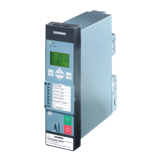
Siemens SIPROTEC 7RW80 Manuals
Manuals and User Guides for Siemens SIPROTEC 7RW80. We have
4
Siemens SIPROTEC 7RW80 manuals available for free PDF download: Manual
Siemens SIPROTEC 7RW80 Manual (260 pages)
Voltage and Frequency Protection
Brand:
Siemens
| Category:
Protection Device
| Size: 4.08 MB
Table of Contents
Functions 3
3
Technical Data
4
Table of Contents
9
1 Introduction
15
Overall Operation
16
Application Scope
18
Characteristics
20
2 Functions
23
General
24
Functional Scope
24
Description
24
Setting Notes
25
Settings
26
Device, General Settings
27
Description
27
Setting Notes
28
Settings
28
Information List
28
Power System Data 1
30
Description
30
Setting Notes
30
Settings
33
Information List
34
Oscillographic Fault Records
34
Description
34
Setting Notes
35
Settings
36
Information List
36
Settings Groups
36
Description
36
Setting Notes
37
Settings
37
Information List
37
Power System Data 2
38
Description
38
Setting Notes
38
Settings
38
Information List
38
EN100-Module
39
Functional Description
39
Setting Notes
39
Information List
39
Voltage Protection 27, 59
40
Measurement Principle
40
Overvoltage Protection 59
41
Undervoltage Protection 27
43
Setting Notes
45
Settings
48
Information List
49
Frequency Protection 81 O/U
50
Description
50
Setting Notes
52
Settings
53
Information List
54
Load Restoration
55
Description
55
Setting Notes
61
Settings
64
Information List
66
Monitoring Functions
68
Measurement Supervision
68
General
68
Hardware Monitoring
68
Software Monitoring
69
Monitoring of the Transformer Circuits
69
Broken Wire Monitoring of Voltage Transformer Circuits
71
Setting Notes
72
Settings
72
Information List
72
Trip Circuit Supervision 74TC
73
Description
73
Setting Notes
76
Settings
77
Information List
77
Malfunction Responses of the Monitoring Functions
77
Description
77
Flexible Protection Functions
79
Functional Description
79
Setting Notes
83
Settings
87
Information List
88
General
89
Synchrocheck 25
90
Functional Sequence
90
De-Energized Switching
92
Direct Command / Blocking
93
Interaction with Control and External Control
93
Setting Notes
94
Settings
99
Information List
100
Overexcit. Protection (Volt/Hertz)
102
Functional Description
102
Setting Notes
104
Settings
106
Information List
106
Jump of Voltage Vector
107
Functional Description
107
Setting Notes
109
Settings
110
Information List
110
Phase Rotation
111
Description
111
Setting Notes
112
Function Logic
113
Pickup Logic of the Entire Device
113
Tripping Logic of the Entire Device
113
Setting Notes
114
Auxiliary Functions
115
Message Processing
115
Leds and Binary Outputs (Output Relays)
115
Information Via Display Field or PC
116
Information to a Control Center
117
Statistics
117
Description
117
Setting Notes
118
Information List
118
Measurement
118
Displaying of Measured Values
119
Transfer of Measured Values
120
Information List
120
Min/Max Measurement Setup
121
Description
121
Setting Notes
121
Settings
121
Information List
122
Set Points for Measured Values
123
Setting Notes
123
Set Points for Statistic
123
Description
123
Information List
124
Energy Metering
124
Setting Notes
124
Settings
124
Commissíoning Aids
125
Description
125
Breaker Control
127
Control Device
127
Description
127
Information List
128
Command Types
129
Description
129
Command Sequence
130
Description
130
Interlocking
131
Description
131
Command Logging
136
Description
136
Notes on Device Operation
137
Different Operation
137
3 Mounting and Commissioning
139
Mounting and Connections
140
Configuration Information
140
Hardware Modifications
144
Disassembly
144
Connections of the Voltage Terminals
147
Interface Modules
147
Reassembly
150
Installation
151
General
151
Panel Flush Mounting
152
Cubicle Mounting
153
Panel Surface Mounting
154
Checking Connections
155
Checking the Data Connections of the Interfaces
155
Checking the System Connections
158
Commissioning
159
Test Mode and Transmission Block
160
Testing the System Interface (at Port B)
160
Configuring Communication Modules
162
Checking the Status of Binary Inputs and Outputs
165
Testing User-Defined Functions
168
Voltage and Phase Rotation Testing
168
Polarity Check for Voltage Input V
169
Trip/Close Tests for the Configured Operating Devices
171
Creating a Test Fault Record
172
Final Preparation of the Device
173
4 Technical Data
175
General Device Data
176
Analog Inputs
176
Auxiliary Voltage
176
Binary Inputs and Outputs
177
Communication Interfaces
178
Electrical Tests
180
Mechanical Stress Tests
182
Climatic Stress Tests
183
Service Conditions
183
Design
184
UL Certification Conditions
184
Voltage Protection (27, 59)
185
Frequency Protection 81 O/U
187
Load Restoration
188
Flexible Protective Functions
189
Synchrocheck 25
191
Overecxitation Protection 24
193
Jump of Voltage Vector
195
User-Defined Functions (CFC)
196
Additional Functions
201
Breaker Control
204
Dimensions
205
Panel Flush and Cubicle Mounting (Housing Size 1/6)
205
Panel Surface Mounting (Housing Size 1/6)
206
Bottom View
206
Appendix
207
Ordering Information and Accessories
208
Ordering Information
208
7 Rw80 V4.6
208
A.1.2 Accessories
212
Accessories
212
7RW80 - Housing for Panel Flush Mounting or Cubicle Mounting
213
A.2 Terminal Assignments
213
Terminal Assignments
213
7RW80 - Housing for Panel Surface Mounting
214
A.3 Connection Examples
215
Connection Examples
215
A.4 Default Settings
219
Binary Input
219
Default Settings
219
Leds
219
A.4.3 Binary Output
220
Binary Output
220
Function Keys
220
A.4.5 Default Display
221
Default Display
221
Protocol-Dependent Functions
223
A.6 Functional Scope
224
Functional Scope
224
A.7 Settings
225
Settings
225
A.8 Information List
231
Information List
231
A.9 Group Alarms
242
Group Alarms
242
A.10 Measured Values
243
Measured Values
243
Literature
245
Glossary
247
Index
259
Advertisement
Siemens SIPROTEC 7RW80 Manual (264 pages)
Voltage and Frequency Protection
Brand:
Siemens
| Category:
Protection Device
| Size: 4.92 MB
Table of Contents
Preface
3
Table of Contents
9
1 Introduction
15
Overall Operation
16
Application Scope
18
Characteristics
20
2 Functions
23
General
24
Functional Scope
24
Functional Description
24
Setting Notes
24
Settings
25
Device, General Settings
26
Functional Description
26
Setting Notes
27
Settings
27
Information List
27
Power System Data 1
28
Functional Description
28
Setting Notes
29
Settings
31
Information List
32
Oscillographic Fault Records
32
Functional Description
32
Setting Notes
33
Settings
34
Information List
34
Settings Groups
34
Functional Description
34
Setting Notes
34
Settings
35
Information List
35
Power System Data 2
35
Functional Description
35
Setting Notes
35
EN100-Module
36
Functional Description
36
Setting Notes
36
Information List
36
Voltage Protection 27, 59
37
Measurement Principle
37
Overvoltage Protection 59
38
Undervoltage Protection 27
39
Setting Notes
41
Settings
44
Information List
45
Frequency Protection 81 O/U
46
Functional Description
46
Setting Notes
47
Settings
48
Information List
49
Load Restoration
50
Functional Description
50
Setting Notes
54
Settings
57
Information List
60
Supervision Functions
61
Measurement Supervision
61
General
61
Hardware Monitoring
61
Software Monitoring
61
Monitoring of the Transformer Circuits
62
Broken Wire Monitoring of Voltage Transformer Circuits
63
Setting Notes
64
Settings
64
Information List
65
Trip Circuit Supervision 74TC
65
Functional Description
65
Setting Notes
68
Settings
68
Information List
69
Malfunction Responses of the Monitoring Functions
69
Functional Description
69
Flexible Protection Functions
71
Functional Description
71
Setting Notes
74
Settings
77
Information List
78
Synchrocheck
80
Allgemeines
80
Functional Sequence
81
De-Energized Switching
82
Direct Command / Blocking
83
Interaction with Control and External Control
84
Setting Notes
84
Settings
88
Information List
89
Overexcit. Protection (Volt/Hertz)
91
Functional Description
91
Setting Notes
93
Settings
95
Information List
95
Jump of Voltage Vector
96
Functional Description
96
Setting Notes
98
Settings
99
Information List
99
Phase Rotation
100
Functional Description
100
Setting Notes
100
Function Logic
101
Pickup Logic of the Entire Device
101
Tripping Logic of the Entire Device
101
Setting Notes
102
Auxiliary Functions
103
Message Processing
103
LED Displays and Binary Outputs (Output Relays)
103
Information on the Integrated Display (LCD) or Personal Computer
103
Information to a Control Center
105
Statistics
105
Functional Description
105
Setting Notes
105
Information List
105
Measurement
105
Display of Measured Values
106
Transfer of Measured Values
107
Information List
107
Min/Max Measurement Setup
108
Functional Description
108
Setting Notes
108
Settings
108
Information List
108
Set Points for Measured Values
109
Setting Notes
109
Set Points for Statistic
109
Functional Description
109
Information List
110
Energy Metering
110
Setting Notes
110
Settings
110
Commissioning Aids
110
Functional Description
110
Breaker Control
112
Control Device
112
Functional Description
112
Informationsübersicht
113
Types of Commands
113
Functional Description
113
Command Sequence
113
Functional Description
114
Switchgear Interlocking
114
Command Logging
118
Functional Description
119
Notes on Device Operation
120
Different Operation
120
3 Mounting and Commissioning
123
Mounting and Connections
124
Configuration Information
124
Hardware Modifications
127
Disassembly
127
Connections of the Voltage Terminals
131
Interface Modules
132
Reassembly
134
Installation
135
General
135
Panel Flush Mounting
136
Cubicle Mounting
137
Panel Surface Mounting
138
Checking Connections
140
Checking the Data Connections of the Interfaces
140
Checking the System Connections
142
Commissioning
144
Test Mode and Transmission Block
145
Testing the System Interface
145
Configuring Communication Modules
146
Checking the Status of Binary Inputs and Outputs
150
Testing User-Defined Functions
152
Voltage and Phase Rotation Testing
152
Polarity Check for Voltage Input V
153
Trip/Close Tests for the Configured Operating Devices
155
Creating Oscillographic Recordings for Tests
156
Final Preparation of the Device
157
4 Technical Data
159
General Device Data
160
Analog Inputs
160
Auxiliary Voltage
160
Binary Inputs and Outputs
160
Communication Interfaces
161
Electrical Tests
164
Mechanical Tests
165
Climatic Stress Tests
166
Service Conditions
167
Constructive Design
167
UL Certification Conditions
167
Voltage Protection
169
Frequency Protection 81 O/U
171
Load Restoration
172
Flexible Protection Functions
173
Synchrocheck 25
175
Overecxitation Protection 24
177
Jump of Voltage Vector
179
User-Defined Functions (CFC)
180
Auxiliary Functions
185
Switching Device Control
188
Dimensions
189
Panel Flush and Cubicle Mounting (Housing Size 1/6)
189
Panel Surface Mounting (Housing Size 1/6)
190
Bottom View
190
A Ordering Information and Accessories
191
Ordering Information 7RW80 V4.6
192
Accessories
195
B Terminal Assignments
197
7RW80 - Housing for Panel Flush Mounting or Cubicle Mounting
198
7RW80 - Housing for Panel Surface Mounting
199
C Connection Examples
201
Connection Examples for Voltage Transformers
202
D Default Settings and Protocol-Dependent Functions
207
Leds
208
Binary Input
209
Binary Output
210
Function Keys
211
Default Display
212
Protocol-Dependent Functions
213
E Functions, Settings, Information
215
Functional Scope
216
Settings
217
Information List
226
Group Indications
246
Measured Values
247
Literature
249
Glossary
251
Index
261
Siemens SIPROTEC 7RW80 Manual (43 pages)
Overcurrent Protection, Motor Protection, Voltage and Frequency Protection
Brand:
Siemens
| Category:
Relays
| Size: 0.48 MB
Table of Contents
Instructions and Warnings
5
Table of Contents
7
Table of Contents
8
Notes to SIPROTEC Objects
9
Binary Inputs / Annunciations
10
Error with a Summary Alarm
10
Alarm Summary Event
10
Binary Outputs / Commands
11
Stop Data Transmission
11
Single Commands
11
Control Mode REMOTE
11
Analog Inputs / Measured Values
12
Changing the Setting Group
12
Scaling
13
Metered Measurands
13
DNP V3.0 Device Profile
15
Implementation Table
16
Device Profile Document
18
Sends/Executes Control Operations
19
Timesync Information
19
Sends Unsolicited Responses
20
Default Counter Object/Variation
20
Sends Static Data in Unsolicited Responses
20
Point Lists
21
Functional Scope
22
7SJ80 Functional Scope
22
7SK80 Functional Scope
23
7RW80 Functional Scope
24
Binary Input Points
25
Auto-Reclose Function
25
Overcurrent Protection
25
Inrush Function
25
Directional Overcurrent Protection
25
Negative Sequence Protection
26
Over/Underfrequency Protection
26
Under/Overvoltage Protection
26
Sensitive) Ground Fault Protection
26
Startup Counter for Motor
27
Startup Supervision of Motors
27
Trip Circuit Supervision
27
Internal Mode Status
27
Control Switches Return Position Indication(Double Point Commands)
27
Internal Controls
28
Output Channels Return Position Indication (Single Point Commands)
28
Internal Controls
29
Control Relay Output Blocks/Binary Output Status
31
External Commands (Double Point Commands)
31
Binary Output Status Points
32
Internal Commands
32
Output Channel (User Defined Single Point Output Commands)
32
Counters
34
Analog Inputs
35
Recorded Measured Values
35
Min/Max Values
35
Statistic Values
36
Glossary
39
Index
41
Advertisement
Siemens SIPROTEC 7RW80 Manual (42 pages)
Overcurrent Protection; Motor Protection; Voltage and Frequency Protection;
Brand:
Siemens
| Category:
Relays
| Size: 0.4 MB
Table of Contents
Preface
3
Revision Index
7
Table of Contents
9
Modbus Register Map Organization
11
Explanations
12
Functional Scope
14
Coil Status Registers (0X Register)
17
Registers 00001 to 00018: Double Commands
17
Registers 00019 to 00043: Single Commands and Taggings
18
Registers 00044 to 00048: Internal Commands
19
Registers 00257 to 00264: Exception Flags
21
Input Status Registers (1X Register)
22
Registers 10001 to 10024: User-Defined Annunciations
22
Registers 10025 to 10033: Auto-Reclose Function
23
Registers 10034 to 10045: Overcurrent Protection
23
Registers 10046 to 10053: Directional Overcurrent Protection
24
Registers 10054 to 10058: Negative Sequence Protection
24
Registers 10059 to 10063: Frequency Protection
24
Registers 10064 to 10069: Under/Overvoltage Protection
25
Registers 10070 to 10081: (Sensitive) Ground Fault Protection
25
Registers 10082 to 10083: Startup Counter for Motors
25
1.4.10 Registers 10084 to 10086: Startup Supervision of Motors
26
1.4.11 Registers 10087 to 10088: Trip Circuit Supervision
26
1.4.12 Registers 10089 to 10090: Local/Mode
26
Input Registers (3X Register)
27
Holding Registers (4X Register)
29
Registers 40001 to 40036: System Information
29
Registers 40065 to 40069: Time Synchronization
30
Register 40129: Diagnostics
31
Registers 40201 to 40208: Metered Measurands
32
Registers 40301 to 40324: Statistic Values
33
Registers 40351 to 40520: Min/Max Values of Measured Values
34
Registers 40601 to 40626: Event Recorder ("Sequence of Events")
37
Advertisement
Related Products
Siemens SIPROTEC 7UT613 series
Siemens SIPROTEC 7UT613*-*D/E series
Siemens SIPROTEC 7ST622
Siemens SIPROTEC 7UM62
Siemens Solkor 7PG2114
Siemens SIPROTEC 7SS60
Siemens Reyrolle 7SR54
Siemens 7SR51
Siemens SIPROTEC 7SJ531
Siemens Solkor 7PG2116
Siemens Categories
Industrial Equipment
Controller
Control Unit
Oven
Washer
More Siemens Manuals
Login
Sign In
OR
Sign in with Facebook
Sign in with Google
Upload manual
Upload from disk
Upload from URL